Anybus Wireless Bolt User manual

Anybus
®Wireless Bolt™
USER MANUAL
SCM-1202-007-EN 2.5 ENGLISH

Important User Information
Liability
Every care has been taken in the preparation of this document. Please inform HMS Industrial Networks AB of any
inaccuracies or omissions. The data and illustrations found in this document are not binding. We, HMS Industrial
Networks AB, reserve the right to modify our products in line with our policy of continuous product development.
The information in this document is subject to change without notice and should not be considered as a
commitment by HMS Industrial Networks AB. HMS Industrial Networks AB assumes no responsibility for any errors
that may appear in this document.
There are many applications of this product. Those responsible for the use of this device must ensure that all the
necessary steps have been taken to verify that the applications meet all performance and safety requirements
including any applicable laws, regulations, codes, and standards.
HMS Industrial Networks AB will under no circumstances assume liability or responsibility for any problems that
may arise as a result from the use of undocumented features, timing, or functional side effects found outside the
documented scope of this product. The effects caused by any direct or indirect use of such aspects of the product
are undefined, and may include e.g. compatibility issues and stability issues.
The examples and illustrations in this document are included solely for illustrative purposes. Because of the many
variables and requirements associated with any particular implementation, HMS Industrial Networks AB cannot
assume responsibility for actual use based on these examples and illustrations.
Intellectual Property Rights
HMS Industrial Networks AB has intellectual property rights relating to technology embodied in the product
described in this document. These intellectual property rights may include patents and pending patent applications
in the USA and other countries.
Anybus®is a registered trademark and Wireless Bolt™is a trademark of HMS Industrial Networks AB. All other
trademarks mentioned in this document are the property of their respective holders.
Anybus®Wireless Bolt™User Manual SCM-1202-007-EN 2.5

Anybus®Wireless Bolt™User Manual SCM-1202-007-EN 2.5
Table of Contents Page
1 Preface ............................................................................................................................... 3
1.1 About This Document.....................................................................................................3
1.2 Document History ..........................................................................................................3
1.3 Document Conventions ..................................................................................................4
2 Description ....................................................................................................................... 5
2.1 Product Description........................................................................................................5
2.2 Bluetooth or WLAN? ......................................................................................................5
2.3 Model Name – Certification Identifier ...............................................................................6
3 Installation ........................................................................................................................ 7
3.1 Safety ...........................................................................................................................7
3.2 General Information .......................................................................................................7
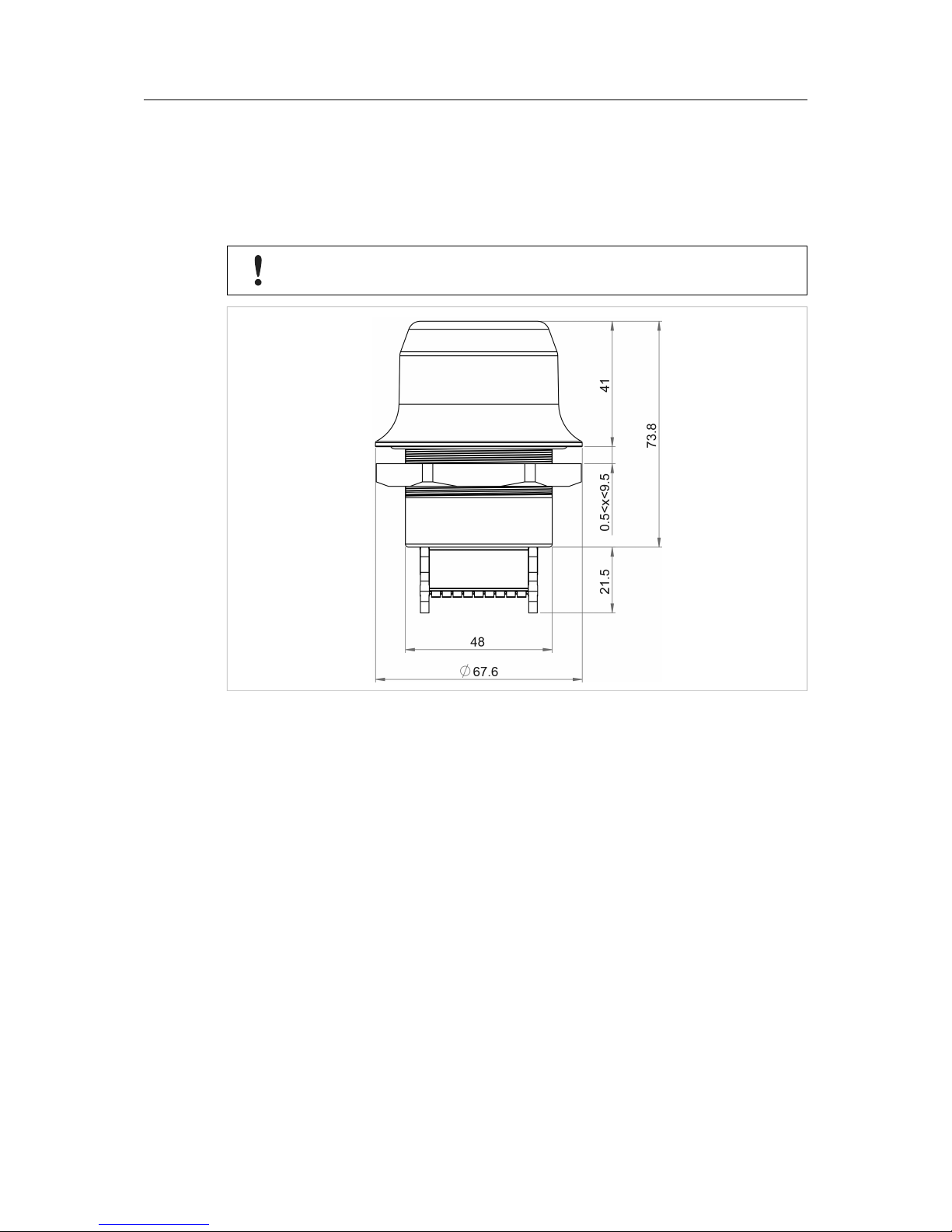
3.3 Mechanical Installation ...................................................................................................8
3.4 Connector .....................................................................................................................9
3.5 Cabling .......................................................................................................................10
4 Configuration ................................................................................................................. 11
4.1 General....................................................................................................................... 11
4.2 Web Interface ..............................................................................................................12
4.3 Factory Restore ...........................................................................................................24
4.4 RESET Button .............................................................................................................25
A Configuration Examples.............................................................................................. 27
A.1 Ethernet Bridge via WLAN or Bluetooth (Easy Config) ....................................................27
A.2 PROFINET networking via Bluetooth (Easy Config) ........................................................28
A.3 EtherNet/IP networking via Bluetooth (Easy Config)........................................................29
A.4 Connecting an Ethernet network to an existing WLAN.....................................................30
A.5 Adding wireless connectivity to a single Ethernet node....................................................31
A.6 Accessing a PLC from a handheld device over WLAN ....................................................32
B Wireless Technology Basics ...................................................................................... 33
C Technical Data................................................................................................................ 34
C.1 Technical Specifications ...............................................................................................34
C.2 Internal Antenna Characteristics ...................................................................................34

This page intentionally left blank

Preface 3 (36)
1 Preface
1.1 About This Document
This manual describes how to install and configure Anybus Wireless Bolt.
For additional related documentation and file downloads, please visit the Anybus support
website at www.anybus.com/support.
Included Additional Files
SCM-1202-061 UL Ord.Loc. compliance information
SCM-1202-062 UL Haz.Loc. compliance information
SCM-1202-063 ATEX compliance information
1.2 Document History
Version Date Description
1.0 2016-09-15 First release
1.1 2016-11-23 Minor additions and updates
1.2 2017-12-14 Added configuration example
2.0 2017-04-19 Updated for SP1
2.1 2017-07-06 Added Bluetooth bridge mode
2.2 2017-10-04 Updated for SP2
2.3 2017-10-18 Updated compliance info
2.4 2017-12-21 Updated for FW 1.3.9
2.5 2018-02-02 Minor update
Anybus®Wireless Bolt™User Manual SCM-1202-007-EN 2.5

Preface 4 (36)
1.3 Document Conventions
Ordered lists are used for instructions that must be carried out in sequence:
1. First do this
2. Then do this
Unordered (bulleted) lists are used for:
• Itemized information
• Instructions that can be carried out in any order
...and for action-result type instructions:
► This action...
➨leads to this result
Bold typeface indicates interactive parts such as connectors and switches on the hardware, or
menus and buttons in a graphical user interface.
Monospaced text is used to indicate program code and other
kinds of data input/output such as configuration scripts.
This is a cross-reference within this document: Document Conventions, p. 4
This is an external link (URL): www.hms-networks.com
This is additional information which may facilitate installation and/or operation.
This instruction must be followed to avoid a risk of reduced functionality and/or
damage to the equipment, or to avoid a network security risk.
Caution
This instruction must be followed to avoid a risk of personal injury.
WARNING
This instruction must be followed to avoid a risk of death or serious injury.
Anybus®Wireless Bolt™User Manual SCM-1202-007-EN 2.5

Description 5 (36)
2 Description
2.1 Product Description
Anybus Wireless Bolt provides wireless communication over WLAN and/or Bluetooth®to wired
networks.
Typical applications for Anybus Wireless Bolt include:
• Adding wireless cloud connectivity to industrial devices
• Accessing devices from a laptop, smartphone or tablet
• Ethernet cable replacement between devices
Limitations:
Bluetooth PAN (Personal Area Network) may not work with some devices due to different
implementations of Bluetooth by different manufacturers.
WLAN 5 GHz cannot be used at the same time as WLAN 2.4 GHz or Bluetooth.
2.2 Bluetooth or WLAN?
Use Bluetooth when...
• ...the wireless link has an Anybus Wireless Bridge II or Anybus Wireless Bolt at both ends.
• ...an interruption-free connection is more important than data throughput speed.
• ...interference robustness is important – e.g. in an industrial environment.
• ...a Profinet I/O cycle time or EtherNet/IP RPI of 64 ms or more is acceptable.
Use WLAN when...
• ...connecting to other types of wireless devices or a WLAN infrastructure.
• ...high data throughput speed is more important than connection reliability.
• ...large file transfers are expected.
• ...WLAN channel frequency planning is possible.
• ...a low Profinet I/O cycle time or EtherNet/IP RPI is desired.
Anybus®Wireless Bolt™User Manual SCM-1202-007-EN 2.5

Description 6 (36)
2.3 Model Name – Certification Identifier
The model name is used to identify the product for various certifications. It consists of a model
prefix followed by two designators for the specific interface configuration and functionality.
Prefix AWB2 Anybus Wireless Bolt
Interface configuration A Interface 18-pin plug
Functionality A
B
C
Ethernet
Ethernet and RS232/485
Ethernet and CAN
Example: AWB2AA = Anybus Wireless Bolt with18-pin connector and Ethernet networking only.
Anybus®Wireless Bolt™User Manual SCM-1202-007-EN 2.5

Installation 7 (36)
3 Installation
3.1 Safety
Caution
This equipment emits RF energy in the ISM (Industrial, Scientific, Medical) band.
Make sure that all medical devices used in proximity to this device meet
appropriate susceptibility specifications for this type of RF energy.
This product is recommended for use in both industrial and domestic environments.
For industrial environments it is mandatory to use the functional earth connection
to comply with immunity requirements. For domestic environments the functional
earth must be omitted if a shielded Ethernet cable is used, in order to meet
emission requirements.
This product contains parts that can be damaged by electrostatic discharge (ESD).
Use ESD prevention measures to avoid damage.
See also additional safety instructions in the included compliance information.
3.2 General Information
Make sure that you have all the necessary information about the capabilities and restrictions of
your local network environment before installation.
The characteristics of the internal antenna should be considered when choosing the placement
and orientation of the unit.
See Technical Data, p. 34 for details about the antenna characteristics.
For optimal reception, wireless devices require a zone between them clear of objects that could
otherwise obstruct or reflect the signal. A minimum distance of 50 cm between the devices
should also be observed to avoid interference.
See also Wireless Technology Basics, p. 33.
Anybus®Wireless Bolt™User Manual SCM-1202-007-EN 2.5

Installation 8 (36)
3.3 Mechanical Installation
Anybus Wireless Bolt is intended to be mounted on top of a machine or cabinet through an M50
(50.5 mm) hole using the included sealing ring and nut.
Tightening torque: 5 Nm ±10 %
Make sure that the sealing ring is correctly placed in the circular groove in the top
part of the housing before tightening the nut.
Fig. 1 Installation drawing
All measurements are in mm.
Anybus®Wireless Bolt™User Manual SCM-1202-007-EN 2.5

Installation 9 (36)
3.4 Connector
The 18-pin connector is common for all models of the Anybus Wireless Bolt. Some pins may
have a different function depending on model. Unused pins should not be connected.
Fig. 2 Connector
The location of the RESET button can be used as a reference for the pin numbering when the
connector is attached to the Wireless Bolt. Pin 1 will be the pin closest to the button.
Pin Name Description
1 VIN Power + (9–30 V)
2 GND Power Ground
3 DI Digital input + (9–30 V)
4DI_GND Digital input ground
5ETN_RD+ Ethernet receive + (white/orange)
6ETN_RD- Ethernet receive - (orange)
7ETN_TD- Ethernet transmit - (green)
8ETN_TD+ Ethernet transmit + (white/green)
9RS485_B RS-485 B Line
10 FE/Shield Ethernet:
Serial:
Functional Earth
Functional Earth and Shield
11 RS232_TXD RS-232 Transmit
12 RS485_A/RS232_RXD RS-485 A Line / RS-232 Receive
13 RS232_RTS RS-232 Request To Send
14 RS232_CTS RS-232 Clear To Send
15 ISO_5V Isolated 5 V for serial interface
16 ISO_GND Isolated Ground for serial interface
17 CAN_L CAN Low
18 CAN_H CAN High
Note:
• The Ethernet wire colors refer to the T568A standard.
• If using a shielded Ethernet cable the shield must be unconnected.
• RS-232 and RS-485 cannot be used at the same time.
• Use termination for RS-485 and CAN when required.
Anybus®Wireless Bolt™User Manual SCM-1202-007-EN 2.5

Installation 10 (36)
3.5 Cabling
To make an Ethernet connector cable for the Anybus Wireless Bolt:
Fig. 3 Ethernet cable
1. Cut off one of the connectors on a standard Cat5e or Cat6 Ethernet cable.
2. Strip off about 40 mm (1½ inch) of the cable jacket and untwist the orange, orange/white,
green and green/white wires. The other wires will not be used.
3. Strip off about 7 mm (¼ inch) of the isolation on each wire.
4. Push the pin spring release next to each socket on the connector and insert the correct
wire end according to Connector, p. 9.
Connect the wires from the power supply in the same way as the Ethernet wiring. Make sure
that polarity is not reversed.
Anybus®Wireless Bolt™User Manual SCM-1202-007-EN 2.5

Configuration 11 (36)
4 Configuration
4.1 General
Anybus Wireless Bolt should normally be configured via the web interface. Parameters can be
set individually or using one of the pre-configured Easy Config modes.
Advanced configuration can be carried out by issuing AT (modem) commands through the web
interface or over a Telnet or RAW TCP connection to port 8080.
The web interface is accessed by pointing a web browser to the IP address of the Wireless Bolt.
The default address is 192.168.0.99. The computer accessing the web interface must be in the
same IP subnet as the Wireless Bolt.
The web interface is designed for the current stable versions of Internet Explorer,
Chrome, Firefox and Safari. Other browsers may not support the full functionality
of the web interface.
Fig. 4 Web interface
Anybus
®Wireless Bolt™User Manual SCM-1202-007-EN 2.5

Configuration 12 (36)
4.2 Web Interface
The web interface is accessed by pointing a web browser to the IP address of the Wireless Bolt.
The default IP address is 192.168.0.99. The computer accessing the web interface must be in
the same IP subnet as the Wireless Bolt.
The web interface is designed for the current stable versions of Internet Explorer,
Chrome, Firefox and Safari. Other browsers may not support the full functionality
of the web interface.
4.2.1 System Overview
Fig. 5 System Overview page
The Save and Reboot button will become enabled if the unit must be restarted for a parameter
change to come into effect.
To revert to the currently active configuration without saving the parameter changes, click on
Cancel All Changes.
Anybus®Wireless Bolt™User Manual SCM-1202-007-EN 2.5

Configuration 13 (36)
4.2.2 Easy Config
Fig. 6 Easy Config page
To activate an Easy Config mode, select it from the dropdown menu and click on Set.
Easy Config Modes
Mode Role Description
2—Reset configuration to factory defaults.
3—Reset IP settings to factory defaults.
4 Client Wait for automatic configuration.
5 WLAN AP Configure units in mode 4 as clients.
Restart as access point and connect clients.6 Bluetooth NAP
7 WLAN AP Configure units in mode 4 as clients.
Restart as access point and connect clients.
Apply PROFINET optimizations to all units.
8 Bluetooth NAP
10 —Apply PROFINET optimizations and restart.
Modes 5 – 8 will scan for units in mode 4. Detected units will be reconfigured as clients, and the
scanning unit will restart as an access point. The clients will then restart and connect to the
access point.
Modes 7 and 8 will additionally apply PROFINET optimization to all the units. PROFINET
messages will then have priority over TCP/IP frames.
Mode Timeout
• Modes 5 – 8 will time out after 120 seconds. Apply the mode again to repeat the scan.
• Mode 4 will listen for 120 seconds or until receiving a configuration.
The IP address of a client may be changed by the configuration from the access
point. Active browser sessions could therefore be lost.
Anybus®Wireless Bolt™User Manual SCM-1202-007-EN 2.5

Configuration 14 (36)
4.2.3 Network Settings
Fig. 7 Network Settings page
IP Assignment Select static or dynamic IP addressing (DHCP)
IP Address Static IP address for the unit
The browser should automatically be redirected to the new address after clicking
on Save and Reboot (not supported by all browsers).
Subnet Mask Subnet mask when using static IP
Default Gateway Default gateway when using static IP
Internal DHCP Server Disabled: No internal DHCP functionality
DHCP Relay Enabled: The unit can receive a DHCP request on one interface
and resend it to a DHCP server located on one of the other interfaces.
Only a single DHCP server can be active for all the connected interfaces.
If WLAN is used, the forwarding mode must be set to Layer 3 IP Forward.
DHCP Server Enabled: Activates an internal DHCP server. This option is only
available when IP Assignment is set to Static.
Do not enable this option if there is already a DHCP server on the network!
Start Address (Y) The internal DHCP server will assign up to 7 IP addresses starting from X.X.X.Y,
where Xis taken from the current static IP address setting, and Yis the value in
Start Address. Already allocated addresses will be skipped, including the
address of the unit itself. The subnet mask setting will be ignored.
Examples:
IP Address: 192.168.0.99, Start Address: 101
DHCP range = 192.168.0.101 – 192.168.0.107
IP Address: 192.168.0.103, Start Address: 101
DHCP range = 192.168.0.101 – 192.168.0.108
7 addresses are allocated but the address of the unit is skipped.
Anybus
®Wireless Bolt™User Manual SCM-1202-007-EN 2.5

Configuration 15 (36)
4.2.4 WLAN Settings – Client Mode
Fig. 8 WLAN Settings – Client
Enable Enable/disable the WLAN interface.
Operating Mode Choose operation as WLAN Client or Access Point. If Access Point is selected,
additional parameters will be visible.
Channel Bands Choose to scan on only the 2.4 GHz or 5 GHz channel band, or on both (default).
The unit must be rebooted to enable the new setting.
The unit can be configured to scan on both the 2.4 GHz and 5 GHz channel bands but can only
communicate on one band at a time.
Scan for Networks Click to scan the selected frequency band(s) for discoverable WLAN networks.
Select a network from the dropdown menu to connect to it.
Connect to SSID To connect manually to a network, enter its SSID (network name) here. This can
be used if the network does not broadcast its SSID.
Authentication Mode Select the authentication/encryption mode required by the network.
Open = No encryption or authentication
Passkey Enter the passkey when using WPA/WPA2-PSK or WEP64/128.
Username, Domain,
Passphrase
Authentication details when using LEAP or PEAP (WPA2 Enterprise).
Channel Select a specific channel to use when scanning for networks. Which channels are
available depend on the Channel Bands setting.
Auto = all channels will be scanned (default).
Anybus®Wireless Bolt™User Manual SCM-1202-007-EN 2.5

Configuration 16 (36)
Fig. 9 WLAN Client – Advanced Settings
Advanced Settings
Bridge Mode Layer 2 tunnel = All layer 2 data will be bridged over WLAN.
Use when multiple devices on both sides of an Ethernet network bridge must be
able to communicate via WLAN (many-to-many).
Only works between Anybus Wireless Bolt or Wireless Bridge II devices.
Layer 2 cloned MAC only = Layer 2 data from only a single MAC address
(specified below) will be bridged over WLAN (many-to-one).
Layer 3 IP forward (default) = IP data from all devices will be bridged over WLAN.
This mode must be used when using the DHCP Relay function.
Cloned MAC Address The MAC address to use with Layer 2 cloned MAC only (see above).
Anybus®Wireless Bolt™User Manual SCM-1202-007-EN 2.5

Configuration 17 (36)
4.2.5 WLAN Settings – Access Point Mode
Fig. 10 WLAN Settings – Access Point
The following settings are specific when Access Point mode is selected.
Network (SSID) Enter an SSID (network name) for the Wireless Bolt.
If this entry is left blank, the unit will generate an SSID which includes the last 6
characters of the MAC ID.
Authentication Mode Select the authentication/encryption mode to use for the access point.
Open = No encryption or authentication
WPA2 = WPA2 PSK authentication with AES/CCMP encryption
WPA2 Passkey Enter a string in plain text or hexadecimal format to use for authentication.
Regular (plain text) passwords must be between 8 and 63 characters.
All characters in the ASCII printable range (32–126) are allowed, except
"(double quote) ,(comma) and \(backslash).
Hexadecimal passwords must start with 0x and be exactly 64 characters.
See also the example passwords below.
Channel Bands,
Channel
Select the WLAN channel band and channel to use for the access point.
Password examples
For plain text passwords a combination of upper and lower case letters, numbers, and special
characters is recommended.
Example of a strong plain text password:
uS78_xpa&43
Example of hexadecimal password:
0x000102030405060708090a0b0c0d0e0f101112131415161718191a1b1c1d1e1f
Do not use the example passwords above in a live environment!
Anybus®Wireless Bolt™User Manual SCM-1202-007-EN 2.5

Configuration 18 (36)
4.2.6 Bluetooth Settings – General
Fig. 11 Bluetooth Settings
Enable Enable/disable the Bluetooth interface.
Operating Mode PANU (Client) = The unit will operate as a Bluetooth PAN (Personal Area
Network) User device. It can connect to another single Bluetooth PANU device or
to a Bluetooth Network Access Point.
NAP (Access Point) = The unit will operate as a Bluetooth Network Access Point.
It can connect to up to 7 Bluetooth PANU devices.
Local Name Identifies the unit to other Bluetooth devices. If left blank, the unit will use a default
name including the last 6 characters of the MAC ID.
Connectable Enable to make the unit accept connections initiated by other Bluetooth devices.
Discoverable Enable to make the unit visible to other Bluetooth devices.
Security Mode Disabled = No encryption or authentication.
PIN = Encrypted connection with PIN code security. This mode only works
between two units of this type and brand (not with third-party devices). PIN codes
must consist of 4 to 6 digits.
Just Works = Encrypted connection without PIN code.
Paired Devices Lists the currently connected Bluetooth devices.
Anybus
®Wireless Bolt™User Manual SCM-1202-007-EN 2.5
Other manuals for Wireless Bolt
3
Table of contents
Popular Industrial Electrical manuals by other brands

valmont
valmont INGAL EPS Pole Technical Instruction

Murata
Murata GRM0335C1E3R2BA01 Series Reference sheet

Murata
Murata GCJ21BR71H683KA01 Series Reference sheet

Murata
Murata GRM219R61H225ME15 Series Reference sheet

Keysight Technologies
Keysight Technologies N5224BU- 605 Installation notes

LEGRAND
LEGRAND 0 590 56 installation instructions

ABB
ABB Tmax XT XT3 Disassembly instructions

Murata
Murata GRM1885C2A680JA01 Series Reference sheet

Gossen MetraWatt
Gossen MetraWatt SINEAX TI 807-1 operating instructions

Murata
Murata GRM1885C1H7R6DA01 Series Reference sheet

Murata
Murata GRM1885C1E103GA01 Series Reference sheet

Murata
Murata GRM1555C1H751GA01 Series Reference sheet