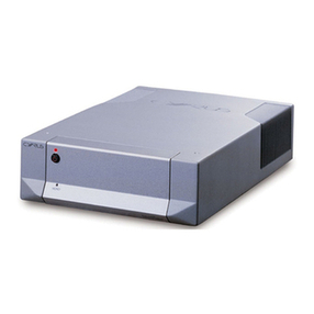
Cyrus aEQ7 User manual

UserInstructions
CyrusaEQ7

Cyrus aEQ7
English

CAUTIONS Cyrus aEQ7
English 2
Congratulations on the purchase of your Cyrus aEQ7
phono pre-amplifier. This piece of equipment is a
precision manufactured state-of-the-art product,
constructed to the highest standards and specifications.
This manual contains installation and operating
instructions to enable the user to connect and operate this
pre-amplifier correctly, thus ensuring the greatest
satisfaction and long term use.
This manual is divided into the following sections.
Cautions.............................................................................2
Installation.........................................................................4
Operation...........................................................................7
Additional Information....................................................8
Trouble Shooting ............................................................10
Specifications...................................................................11
Guarantee........................................................................12
To enable you to make full use of the comprehensive
facilities of your phono pre-amplifier please read all these
sections which explain the operations of the unit in detail.
Important Note: Because of the very low levels of input
signal, please read the manuals accompanying your
amplifier, turntable, tone-arm and cartridge before
installing the Cyrus aEQ7. You should always adhere to
the recommendations of your cartridge manufacturer.
UNPACKING
Always follow the instruction manual and retain it in a
safe place for future reference.
Before proceeding with installing the Cyrus aEQ7, ensure
that the following items are included in the accessory box:
•Instruction Manual
•2 Phono Shorting Plugs
•Power Cable
•2 RCA Cables for MC-Bus connections
•Guarantee Card
After removing these items, please retain the packing for
future use.
CAUTION
POLARISED CONNECTOR (115V PRODUCTS ONLY)
CONNECTOR POLARISE (PRODUITS 115V SEULEMENT)
To prevent electrical shock, match wide blade of plug to wide
slot and fully insert
Attention: Pour éviter les chocs électriques, introduire la lame la
plus large de la fiche dans la borne correspondante de la prise et
pousser jusqu'au fond.

Cyrus aEQ7 CAUTIONS
3English
SUPPLY VOLTAGE
Your Cyrus aEQ7 pre-amplifier is set to operate from the
mains supply voltage marked on the rear of the unit.
Ensure this voltage is the same as your mains supply, i.e.
230V Products Voltage Range 220V-240V
115V Products Voltage Range 110V-120V
Consult your Mission distributor to arrange for conversion
of your Cyrus aEQ7 if you move to an area with a
different mains voltage.
LOCATION
Install the Cyrus aEQ7 in a well-ventilated location where
it will not be exposed to high temperature or humidity.
Avoid installing the Cyrus aEQ7 in a location, which is
exposed to direct sunlight, or near hot appliances or
radiators. Placing the unit on heat generating sources or
installing it in damp or dusty conditions will affect
performance and may result in malfunction or accident.
GENERAL NOTES ON POSITIONING
The Cyrus aEQ7 may be positioned either free standing or
alongside another piece of audio equipment. Never stand
the Cyrus aEQ7 under another unit. This may adversely
affect the cooling of the Cyrus aEQ7. Never place the unit
on any surface, which may hamper normal ventilation.
PRECAUTIONS REGARDING INSTALLATION
Do not allow any liquids or foreign objects to fall into this
unit. When routing the power cord avoid running it over or
near sharp objects. Do not stand objects on the power cord.
If the Cyrus aEQ7 is not to be used for a long period of
time, unplug the unit from the mains power supply.
This unit contains no user serviceable parts.
Never remove any panels from the unit or attempt to
service the unit. In the unlikely event of failure, please
refer to qualified service personnel.
Important Note for UK Customers
The mains lead of this unit is fitted with a UK 13A Plug. Do
NOT disassemble this plug. If for any reason you remove the
plug, dispose of it safely and do not attempt to re-use it.
The wires in the mains lead are coloured in accordance with
the following code: Blue - neutral, Brown - live.
If these colours do not correspond with the coloured
markings identifying the terminals on your new mains plug:
Connect the Blue wire to the terminal which is marked with
the letter Nor coloured Black.
Connect the Brown wire to the terminal, which is marked
with the letter Lor coloured Red.
Ensure that your equipment is connected correctly. If in
doubt, consult a qualified electrician.

INSTALLATION Cyrus aEQ7
English 4
CONNECTING POWER TO THE UNIT
Refer to figure 1, rear panel drawing above.
Plug the moulded IEC connector of the supplied mains
lead into the power inlet on the rear of the unit.
The mains fuse is located on the rear panel. It must only be
replaced with the following types:
U.K. / Europe - 230V T100mA/20mm
N. America / Far East - 115V T200mA/20mm
In the U.K., the Cyrus aEQ7 power lead is supplied fitted
with a mains plug. If the plug fuse should need replacing
ensure that it is replaced only with a 3 Amp Fuse.
CONNECTING A CYRUS PSX-R
If a Cyrus PSX-R is to be used with the Cyrus aEQ7,
connect the umbilical cord of the PSX-R to the 5-pin
Cannon input socket of the Cyrus aEQ7. When correctly
fitted the connector will latch into place in the socket.
No other connections or internal modifications to the
Cyrus aEQ7 are needed for PSX-R connection.
Note: Please ensure that the Cyrus aEQ7 and the PSX-R
are unplugged from the mains before connecting the units.
When a PSX-R is in use, both the Cyrus PSX-R power
supply and the Cyrus aEQ7 will require mains power. For
more details refer to the Cyrus PSX-R Instruction Manual.
1. MC Loading Switch
2. Moving Coil Input
3. Moving Magnet Input
4. Pre-amplifier Output
5. MC-BUS System Connections
6. PSX-R Connection
7. Power Inlet
8. Mains Fuseholder
9. MM Ground Terminal
10. MC Ground Terminal
Fig. 1 Cyrus aEQ7 (rear view)
MC GROUND MM GROUND
USE
ONLY
OUTPUTMM INPUTMC INPUT MC-BUS
10
1k
100
10 1nF
100 1nF
1k 1nF

Cyrus aEQ7 OPERATION
5English
GROUND CONNECTIONS
Before connecting any input ensure that the turntable
motor and tone arm are securely grounded to the Cyrus
aEQ7.
There are two grounding systems in common use:
•The motor and tone-arm grounds are internally
connected with a common ground wire. Connect this wire
to either the MM or MC ground terminal j or 1),
depending on the type of cartridge used.
•There are two ground wires, one from the motor and
one from the tone-arm. Connect both these wires to the
appropriate ground terminal on the Cyrus aEQ7.
Note: There are other grounding systems – refer to
Additional Information on Page 9 for further details.
CONNECTING SOURCE INPUTS
The Cyrus aEQ7 accepts Moving Coil and Moving
Magnet cartridge inputs. If you have one turntable
equipped with a MM and another one with an MC
cartridge, both can be connected at the same time.
The Cyrus aEQ7 is supplied with a pair of special shorting
phono plugs. When using only one input, place a shorting
plug into the left and right inputs of the unused inputs.
Note: These shorting plugs must only be used as
described above. They should not be confused with regular
phono plugs.
MOVING MAGNET (MM) INPUT
The MM input daccepts the following cartridges:
•Regular moving magnet cartridges
•High output moving coil cartridges
•Low output moving coil cartridges connected via step-
up devices
The MM input requires no special loading provisions.
MOVING COIL (MC) INPUT
The MC Input cis designed exclusively for use with low-
output moving coil cartridges without step-up devices.
Load matching – MC cartridges
Some MC cartridges are load sensitive and some may also
require an external capacitance load.
Your Cyrus aEQ7 is provided with a loading switch bso
that you can set up your MC cartridge for optimal
response.
Three load settings are available, 10Ω, 100Ωand 1KΩ.
Each load setting is available with or without a 1nF shunt
capacitor. These shunt settings occupy the last three
positions on the switch. Unless your cartridge instructions
advise otherwise, do not use any capacitance loading.
Unless your cartridge instructions recommend otherwise,
we suggest you use the 1KΩsetting.

INSTALLATION Cyrus aEQ7
English 6
CONNECTING A TURNTABLE
Most turntables will be provided with a suitable signal
cable terminated with RCA phono plugs. If, however your
turntable uses phono sockets and no interconnect cable has
been provided, please refer to the Additional Information
section on page 9 for guidance.
Input Connections
1. Ensure the grounding lead is securely connected to the
correct input ground terminal.
2. Plug the RCA connectors of your tone-arm lead into
the appropriate rear panel input sockets c or d.
Observe the colour coding of the phono plugs for left
and right channel identification. The standard
convention is– Right Channel RED, Left Channel
WHITE or BLACK.
3. If you are using only one turntable, plug the shorting
plugs into the unused input sockets.
Always check the technical specification of source
products before connecting them to your Cyrus aEQ7. If
you are unsure of your cartridge type we suggest you
connect it into the MM input.
Note: Connecting a MM type cartridge to the MC sockets
will overload the input and may damage your amplifier
and loudspeakers.
Consult your dealer if in doubt.
OUTPUT CONNECTIONS
The output sockets eof the Cyrus aEQ7 should be
connected to a line level input on your pre-amplifier.
For maximum functionality we recommend the following
inputs when connecting the Cyrus aEQ7 to other Cyrus
products.
Cyrus aCA7 Use the AUX2 input
Cyrus IIIi, Cyrus Pre Use the Phono (PH) input*
*By changing the existing phono module internally, the
Phono input (PH) of the Pre and IIIi can be modified to a
line level input precisely matched to the Cyrus aEQ7.
Note: only an appointed Cyrus dealer should perform this
operation.
Cyrus III Use AU, CD or TU input
Cyrus AV master, Cyrus MR3 Use any input
Cyrus SL Use any input
For making connections use a high quality screened
interconnect. Be careful not to confuse left and right
channels. The standard convention for phono connections
is: Right Channel RED, Left Channel WHITE or BLACK.

Cyrus aEQ7 OPERATION
7English
POWER CONTROL
Refer to figure 2, front panel drawing above.
The STANDBY key bis used for power control. The
Standby light cwill show Red when the Cyrus aEQ7 is
off and Green when operating.
SELECTING AN INPUT
Depress the MC dor MM key eto select the appropriate
input. The red indicator above the key will turn on.
PLAYBACK EQUALISATION
With the Cyrus aEQ7 you can select the traditional RIAA
response or the newer IEC curve.
Press the IEC key fto select the IEC response. The red
indicator above the key will turn on. When the IEC
indicator is unlit, RIAA response is selected.
Fig. 2 Cyrus aEQ7 (front view)
MC MM IEC
1. Standby Switch
2. Standby Light
3. MC Switch
4. MM Switch
5. RIAA/IEC Selector

ADDITIONAL INFORMATION Cyrus aEQ7
English 8
MC-BUS SYSTEM CONNECTION
MC-Bus can provide the option of unified power control
for a Cyrus system from the Cyrus system amplifier. MC-
Bus connections are wired as a 'loop' with single RCA
phono interconnects. Instructions for MC-Bus connection
are included in the handbook for all Cyrus amplifiers with
MC-Bus connections.
OPERATION WITH MC-BUS CONNECTED
With MC-Bus installed, and the Cyrus aEQ7 connected as
recommended, Standby operation of the Cyrus aEQ7 will
be controlled by the system amplifier.
Cyrus aCA7, Cyrus Pre, Cyrus IIIi:When used with
these units in an MC-Bus loop, selecting the input
recommended will switch on the Cyrus aEQ7 from
Standby. This is the default factory setting.
Cyrus III, AV master, MR3:To operate MC-Bus with
these units your Cyrus aEQ7 requires initialisation.
Set the Cyrus aEQ7 to Standby. Press the IEC key f. and
hold it down for two seconds. The indicator above the IEC
key will flash once. The Cyrus aEQ7 will now recognise
MC-Bus commands from the Cyrus III, AV master and
MR3. Take the Cyrus aEQ7 in and out of Standby to
register this setting.
To restore normal operation, repeat this process. The IEC
indicator will flash twice. Remember to take the unit in
and out of Standby to register the new setting.
KNOW YOUR CYRUS aEQ7
Power Supply and Noise Performance
To minimise noise the Cyrus aEQ7 uses a special low-
leakage, fully shielded transformer. Specially designed to
minimise radiated mains harmonics, this transformer has
the lowest measured leakage Cyrus has ever achieved.
Additionally, to reduce Eddy currents a special slit-foil
screen shields the input circuitry from the mains supply.
Microcomputers, while offering convenience and ease of
use also radiate H.F. noise. Special opto-isolators in the
Cyrus aEQ7 fully isolate the internal microcomputer’s
digital signals from the sensitive analogue stages, reducing
coupled noise to negligible levels.
MC and MM Circuit Topology
MC and MM cartridges require completely different
circuit topologies. To match your cartridge characteristics
the Cyrus aEQ7 provides a dedicated input for each type.
Each input also has its own star earth to localise turntable
ground returns and improve common mode rejection.
Non Volatile Memory Storage
When you enter Standby, the Cyrus aEQ7 stores all its
settings as last used. These are recalled when the unit is
next used even if it has been switched off at the mains.
Note. If you switch off at the mains without entering
Standby, new settings will not be stored. The unit will
retain the settings in use the last time Standby was entered.
Cyrus aEQ7 ADDITIONAL INFORMATION
9English
PSX-R REGULATED POWER SUPPLY -
The PSX-R is a highly regulated DC power supply. Its use
will upgrade the sonic performance of your Cyrus aEQ7.
No adjustments are necessary when connecting the Cyrus
PSX-R to the Cyrus aEQ7 - full connection instructions
can be found on page 4.
RIAA or IEC?
In the early 1970s the playback characteristics of phono
reproducers were amended. Many audiophiles feel that this
new IEC curve with its steeper bass roll-off results in a
poorer bass response than the original RIAA curve. The
Cyrus aEQ7 offers you the choice of both.
If your turntable is prone to feedback or rumble and/or
your loudspeakers have a highly extended bass response,
you may occasionally experience some disturbance in the
deep bass when using RIAA as against IEC correction.
INTERCONNECTS
Quality interconnects are essential for good fidelity and
effective screening against hum and noise. Many low cost
interconnects are unscreened or offer minimal screening.
If you need a tone-arm interconnect ask for a quality low-
capacitance fully screened lead. It will be worth the
investment.
Never extend tone-arm leads. Doing so can cause poor
H.F. response, hum and noise.
TURNTABLE AND AMPLIFIER GROUNDING
The grounding of modern cartridges and tone-arms is
straight-forward and installation should be trouble free.
Some older units use a cartridge ground lead to carry the
turntable and tone-arm ground which is why you may not
see a ground return connection from the turntable.
Although not in accord with best modern practice, this
method is acceptable.
Some cartridges have a link connecting one of the negative
signal pins to the metal cartridge shield. With certain tone-
arms this link could make connection between the tone-
arm metal work and the cartridge ground return and set up
a hum loop through the Cyrus aEQ7. If you think this is
the case with your turntable, ask your dealer’s help before
you remove this tag.
If you are using the Cyrus aEQ7 with equipment that
requires a mains earth, do not use the MM or MC ground
terminals for this purpose. Use an appropriate ground
terminal on the ancillary equipment.
HUM AND NOISE
Take care to place your Cyrus aEQ7 and turntable as far as
possible from amplifiers, TV sets and appliances.
As well as turntables, the Cyrus aEQ7 benefits from
placement away from loudspeakers and other sources of
mechanical disturbance.

TROUBLESHOOTING Cyrus aEQ7
English 10
TROUBLESHOOTING GUIDE
If you suspect your Cyrus aEQ7 is not operating to
specification, check carefully all system connections. If
problems persist, the checklists below may help.
If these suggestions fail to resolve the problem, please
return the suspect unit to your dealer for his attention.
Ensure the power to all units is switched off before
altering any connections and only switch the power on
again when the new connections are fully made.
No sound from either speaker
•Check the connections to your cartridge, tone-arm,
Cyrus aEQ7, the associated amplifier and speakers.
•Check that the Cyrus aEQ7 and associated units are
operational. Cyrus standby lights should all be green.
•Check that the correct input (MM/MC) is selected.
•Check that the system amplifier is set to the correct
input and is not muted or set to minimum volume.
No Sound from One Speaker
•Check the connections to your cartridge tone-arm
Cyrus aEQ7, the associated amplifier and speakers.
•If your loudspeakers are fitted with protection fuses,
check that the fuse is intact.
•Check the Balance Control is not at an extreme limit.
•Try another interconnect cable between the Cyrus
aEQ7 and the amplifier.
If the problem persists:
•Interchange left and right channels at the Cyrus aEQ7
input. If the missing channel switches over there is a
problem with the cartridge or the interconnect cable.
Muffled or Distorted Sound on Both Channels
•Check that the tone-arm ground wire is connected.
•Check stylus condition, alignment and tracking force.
•A MM cartridge may be connected to the MC input.
•An MC cartridge is being used with too low a load.
Distortion on One Channel
•Check stylus condition, alignment and tracking force.
The sound level is too low but the quality is OK
•A MC cartridge may be connected to the MM input.
Hum Or Interference is Present in The Background
•Check that the tone-arm ground wire is connected.
•Reposition your turntable, check for sources of
interference e.g. computers, mains transformers, etc.
If the problem persists:
•Refer to your dealer for assistance.
Note: Restore the system to its original configuration after
completion of all tests.

Cyrus aEQ7 SPECIFICATIONS
11 English
AUDIO PERFORMANCE
MC Input
Input Sensitivity (Nom.) ........................................... 210µV
Input Impedance (Switchable) ................... 1kΩ, 100Ω, 10Ω
Overall Gain...............................................................60dB
Input Overload level
(1kHz <0.01%THD) ...........................................12.7mV rms.
Output Headroom
(ref. 500µV input, 1kHz) .................................................28dB
Channel Balance................................................... +/-0.2dB
Crosstalk (20kHz, 500µV input)....................................-80dB
S/N ratio (ref. 500µV input, I/P shorted)
Unweighted ..............................................................-70dB
A-weighted.............................................................-84dBA
THD
(ref. 500µV input) ............................................... 0.05%
MM Input
Input Sensitivity (Nom.) ............................................2.7mV
Input Impedance ........................................................47kΩ
Overall Gain............................................................37.5dB
Input Overload level
(1kHz <0.01%THD) ............................................120mV rms.
Output Headroom
(ref. 5mV input, 1kHz)....................................................27dB
Channel Balance................................................... +/-0.2dB
Crosstalk (20kHz, 5mV input).......................................-90dB
S/N ratio (ref. 5mV input, I/P shorted)
Unweighted ..............................................................-78dBA
A-weighted ...............................................................-92dBA
THD (ref. 5mV input)...................................................0.01%
Output
Output Voltage (Nom.) ............................................200mV
Frequency Response
(RIAA/IEC curve, 20Hz – 20kHz)....................................±2dB
Output Impedance........................................................47Ω
POWER SUPPLY
Voltage .............. See the plate attached to the rear of unit
Power Consumption
Standby ......................................................................... 2W
Operational ................................................................... 9W
Safety ...........................................Compliant to EN 60065
EMC
Compliant to EN55013 & EN55022 .......................Europe
ENCLOSURE
Dimensions (WxHxD) ...........................215 x 75 x 365 mm
Weight...................................................................... 3.1Kg.
Material......................................................Die cast chassis
The company reserves the right to change this specification without prior notice.
Iss.01-9805 File: HA7U8505.WIM

GUARANTEE Cyrus aEQ7
English 12
PRE-AMPLIFIER MAINTENANCE
There are no user serviceable parts in the Cyrus aEQ7 so
do not remove any of the panels. After disconnecting the
mains power supply, the cabinet may be cleaned using
slightly moistened chamois leather. DO NOT use cleaning
agents containing alcohol, spirits, ammonia or abrasives.
THE MISSION/CYRUS GROUP MANUFACTURES
•Power Amplifiers
•Pre-Amplifiers
•Integrated Amplifiers
•Compact Disc Players
•Tuners
•Multi-Room Audio Controllers
•Regulated Audio Power Supplies
•D-to A Converters
•Home Theatre Processors
•High Fidelity Loudspeakers
•Loudspeaker Stands
•Loudspeaker Cables
•Automotive Hi-fi Products
GUARANTEE
This guarantee only becomes effective if the guarantee card
enclosed is completed by the Dealer and the purchaser and
returned to MISSION or Distributor within 8 days of purchase.
This guarantee excludes:
i) All damage caused through accident, misuse, wear and
tear, neglect or through incorrect installation, adjustment
or repair by unauthorised personnel.
ii) Liability for damage or loss occurring in transit to or from
the purchaser.
Claims under this guarantee should be made through the Dealer
from whom the equipment was purchased or if not convenient,
through another authorised MISSION/CYRUS dealer.
MISSION shall not be liable for consequential damage, loss or
injury, arising from or in conjunction with this equipment.
The cost of return carriage shall be borne by the purchaser.
This guarantee is personal to the original Purchaser and is not
transferable.
If equipment is found on examination to comply with the
published specification, MISSION reserves the right to make a
charge for examination and for return carriage.
No Dealer or Distributor may vary the terms of this guarantee.
Any unauthorised servicing will result in loss of guarantee.
We strongly recommend that you retain the sales receipt for
your CYRUS equipment in case of any warranty claim.
The above conditions do not affect your statutory rights.
Table of contents
Other Cyrus Amplifier manuals

Cyrus
Cyrus Power User manual

Cyrus
Cyrus i7-XR User manual

Cyrus
Cyrus 7 User manual

Cyrus
Cyrus 6 Power User manual

Cyrus
Cyrus Two User manual

Cyrus
Cyrus CLASSIC POWER User manual

Cyrus
Cyrus Classic PRE User manual

Cyrus
Cyrus aPA7.5 Mono Installation instructions

Cyrus
Cyrus Pre User manual

Cyrus
Cyrus 6a User manual

Cyrus
Cyrus 6 DAC User manual

Cyrus
Cyrus aCA7.5 User manual

Cyrus
Cyrus AV5 User manual

Cyrus
Cyrus ONE HD User manual

Cyrus
Cyrus DAC X Signature User manual

Cyrus
Cyrus XPA User manual

Cyrus
Cyrus SmartPower User manual

Cyrus
Cyrus Pre vs2 User manual

Cyrus
Cyrus DAC XP Signature User manual

Cyrus
Cyrus POWER-XR User manual