cytiva P-1 User manual

Table of Contents
Important user information ................................................................................................... iii
1 Introduction ........................................................................................................ 5
2 Product Description ........................................................................................... 6
2.1 Main panel ........................................................................................................................................................ 7
2.2 Side panel .......................................................................................................................................................... 9
2.3 The pump mechanism ................................................................................................................................. 11
3 Installation .......................................................................................................... 12
3.1 Unpacking ......................................................................................................................................................... 13
3.2 Mains installation .......................................................................................................................................... 14
3.3 Assembling the pump tubing .................................................................................................................... 16
3.4 Inserting the tubing ...................................................................................................................................... 17
3.5 Setting the flow rate ...................................................................................................................................... 18
4 Operation ............................................................................................................ 19
4.1 Using Peristaltic Pump P-1 in chromatography ................................................................................. 20
4.2 Connecting the pump .................................................................................................................................. 21
4.3 Connections to the remote control socket .......................................................................................... 23
4.4 Calibration of volume information .......................................................................................................... 24
5 Maintenance ....................................................................................................... 25
6 Technical Specifications .................................................................................... 27
7 Accessories and Spare Parts ............................................................................. 28
Appendix A: Solvent resistance of the pump tubing .............................................. 29
Table of Contents
2 Peristaltic Pump P-1 User Manual 59469801 AM

Important user information
All users must read this entire manual to fully understand the safe use of Peristaltic
Pump P-1.
IMPORTANT
Peristaltic Pump P-1 is intended for research use only, and should
not be used in any clinical or in vitro procedures for diagnostic
purposes.
Safety notices
This manual contains warnings and cautions concerning the safe use of the product.
See definitions below.
WARNING
The WARNING symbol and notice highlight instructions that must
be followed to avoid personal injury. Do not proceed until all stated
conditions are clearly understood and met.
CAUTION
The CAUTION notice highlights instructions that must be followed
to avoid damage to the product or other equipment. Do not
proceed until all stated conditions are met and clearly understood.
Notes
A Note is used to indicate information that is important for trouble-free and optimal
use of the product.
Recycling
This symbol indicates that the waste of electrical and electronic
equipment must not be disposed as unsorted municipal waste and
must be collected separately. Please contact an authorized represen-
tative of the manufacturer for information concerning the decommis-
sioning of equipment.
Important user information
Peristaltic Pump P-1 User Manual 59469801 AM iii

WARNING
This is a Class A product. In a domestic environment, it might cause
radio interference, in which case the user might be required to take
appropriate measures.
WARNING
All repairs should be done by personnel authorized by Cytiva. Do
not open any covers or replace parts unless specifically stated in
the instructions.
Important user information
iv Peristaltic Pump P-1 User Manual 59469801 AM

1 Introduction
Intended use
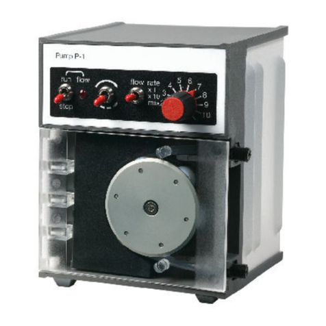
Peristaltic Pump P-1, (Code No. 18-1110-91), is a single channel laboratory pump for
use in liquid chromatography and other applications where accurately controlled liquid
flows are required.
Functional description
Pumping action is provided by a roller cage driven by a stepper motor controlled by a
range selector and a continuously variable potentiometer. The motor speed is almost
independent of temperature (0–40 °C) and load thus giving an accurate and reprodu-
cible flow rate under all conditions.
An asymmetric shape gives the pump a very low pulsation in the forward direction. The
reverse direction has a pulsation which is more similar to traditional peristaltic pumps.
Maximum flow function and a connector for remote control and pulse counting are
provided.
1 Introduction
Peristaltic Pump P-1 User Manual 59469801 AM 5

2.1 Main panel
Roller cage
Pressure plate
Tubing connector
Flow rate pot.
Flow switch Flow rate switch
Run/Stop
switch
Flow LED
Figure 2.1: The front panel
RUN/STOP Switch
Starts and stops the pump. Can be overridden by the remote control.
Flow LED
Indicates that the pump is turned on. The pump will now run if not overridden by the
remote control.
Flow Switch
A switch to reverse the flow.
Note: Because of the asymmetric design of the pressure plate, the forward direc-
tion (unbroken arrow on the switch) shows less pulsation than the reverse
direction (broken arrow).
2 Product Description
2.1 Main panel
Peristaltic Pump P-1 User Manual 59469801 AM 7

Flow rate switch
A range selector for the flow rate. The switch gives a ten-fold variation of the flow rate.
Pressing the switch to the spring loaded bottom position gives maximum flow rate
independent of the potentiometer setting.
Flow rate potentiometer
A continuously variable potentiometer for the control of the flow rate. Gives a linear
response in the range from 1 to 10.
Flow rate guide
Approx. flow rate (ml/ml
Setting
1 2 3 4 5 6 7 8 9 10
×10 ×1
500 50
400 40
300 30
200 20
100 10
Figure 2.2: Flow rate guide
A guide showing the relationship between the flow rate and the setting for different
tube diameters is delivered with the equipment. One side of the flow rate guide is adhe-
sive and should be used to stick the guide onto the clear plastic lid.
2 Product Description
2.1 Main panel
8 Peristaltic Pump P-1 User Manual 59469801 AM
2.2 Side panel
Remote
Figure 2.3: The side panel viewed when the pump is on its back
Mains voltage selector
The socket for mains inlet contains a rotary switch for selection of the appropriate
voltage. The voltages are 100, 120, 230 and 240 V.
Note: Use 230 V setting for 220 V~ mains.
Fuse
Protects the electronics from damage in case of short circuiting. The fuse is located in
the same place as the mains voltage selector. See Fig. 3.1, on page 15.
Remote control
15 pin connector of D-type. The numbers referred to are imprinted on the connector.
Table 2.1: Outputs (TTL open collector 5V)
Pin number Function Technical data
Pin 4 Output, rotation direc-
tion sensin
0=Pump On, 1=Pump off
2 Product Description
2.2 Side panel
Peristaltic Pump P-1 User Manual 59469801 AM 9

Pin number Function Technical data
Pin 13 Output , actual speed TTL open collector 5V
0=Pump On, 1=Pump off
Pin 15 Earth
Pin 10 ON/OFF 0=Pump On, 1=Pump off
Table 2.2: Inputs (TTL Activation)
Pin number Function Technical data
Pin 12 Internal/external speed
control
TTL activation
1=internal, 0=external
Pin 14 External speed control 0–200 Hz, pin 12 must be
0 (see above).
Pin 3 Internal/external rotation
control
1= internal, 0= external
Pin 2 External rotation control 1= forwards, 0=back-
wards.
Pin 3 must be 0 (see
above)
2 Product Description
2.2 Side panel
10 Peristaltic Pump P-1 User Manual 59469801 AM

2.3 The pump mechanism
The roller cage
Contains six polytetrafluoroethylene (PTFE) pumping rollers mounted between two
aluminium plates, which hold the roller bearings. As the cage rotates, the rollers rotate
in the opposite direction, driven by drive wheels which engage the chassis cog ring. The
roller diameter and the gear ratio have been chosen so that the points of the rollers in
contact with the pump tubing are stationary with respect to the tubing. Waves of
compression thus pass along the tubing without dragging the tubing in the direction of
movement of the roller cage.
The pressure plate
An asymmetric semi-circular formed plate which presses the tube against the rollers.
The correct pressure is automatically set by a ball and spring construction when the lid
is closed. The pump accepts all three standard dimensions of tubing without adjust-
ment.
The tubing
The pump accepts three standard dimensions of tubing: i.d. 1.0, 2.1 and 3.1 mm. The
supplied connectors function as stop collars when mounted on the tubing.
Three qualities of tubings are available for the P-1 pump: silicone, PVC and fluoro-
rubber. The silicone tubing is preferred for most aqueous applications because of its
excellent mechanical properties while PVC and fluoro-rubber tubing extend the range
of applications to include most organic solvents (see Appendix A Solvent resistance of
the pump tubing, on page 29).
2 Product Description
2.3 The pump mechanism
Peristaltic Pump P-1 User Manual 59469801 AM 11

3.1 Unpacking
Carefully unpack Peristaltic Pump P-1. Check the contents against the packing list
supplied. Inspect for any damage that may have occurred during transit. Report any
damage immediately to your local Cytiva representative and to the transport company
concerned. Save the packing material if future transport can be foreseen.
3 Installation
3.1 Unpacking
Peristaltic Pump P-1 User Manual 59469801 AM 13

3.2 Mains installation
Before connecting Peristaltic Pump P-1 to the electrical power supply, read the
following instructions carefully:
Step Action
1Two Electrical Power Supply Kits are supplied with Peristaltic Pump P-1, one
for 100–120 V and one for 220–240 V. Choose the kit appropriate to your
mains supply voltage, and discard the other kit.
WARNING
Installing the wrong mains kit can endanger personal
safety and cause irreparable damage to the pump.
Always connect Pump P-1 to a properly grounded mains
supply.
WARNING
Only use mains cables delivered or approved by Cytiva.
WARNING
Do not block the rear panel of the system. The mains
power cord and the power outlet must always be easy to
access because they are used to disconnect the pump
from the electrical supply during emergencies.
2Remove the yellow warning label covering the fuse/voltage selector the real
panel (Fig. 2.3, on page 9).
3Open the fuse/voltage selector with the key provided or with a thin screw-
driver (image a in Fig. 3.1, on page 15).
3 Installation
3.2 Mains installation
14 Peristaltic Pump P-1 User Manual 59469801 AM

Step Action
4Place the fuse appropriate to your mains supply voltage in the fuse holder
and insert it into the right-hand position (image b in Fig. 3.1, on page 15).
The left hand position is a holder for a spare fuse (included in the Mains Kit).
c
b
a
Figure 3.1: Setting the correct mains voltage
5Remove the voltage selector switch, select the correct voltage, and replace
the switch with the correct voltage showing (image c in Fig. 3.1, on page 15).
Note:
Use 230 V for 220 V ~ mains outlet.
6Close the fuse/voltage selector cover and make sure the chosen voltage is
shown in the window.
7Connect the pump to a grounded mains outlet using the cable included in
the Mains Kit.
3 Installation
3.2 Mains installation
Peristaltic Pump P-1 User Manual 59469801 AM 15

3.3 Assembling the pump tubing
Assemble the pump tubing by inserting one connector in each end of the tubing. The
distance between the nuts of the two connectors must be 140 mm (see the Figure
below). This length ensures firm positioning of the tubing.
140 mm
Figure 3.2: The pump tubing
3 Installation
3.3 Assembling the pump tubing
16 Peristaltic Pump P-1 User Manual 59469801 AM

3.4 Inserting the tubing
Step Action
1Open the lid.
2Push back the pressure plate.
3Insert the tubing (Fig. 3.3, on page 18). Make sure the nuts of the connec-
tors fit correctly into their housings.
4Close the lid. The correct tubing pressure is set automatically.
3 Installation
3.4 Inserting the tubing
Peristaltic Pump P-1 User Manual 59469801 AM 17

3.5 Setting the flow rate
Peristaltic Pump P-1 has two flow rate ranges for each tubing diameter. The appro-
priate range is chosen by setting the flow rate switch for ×1 or ×10 giving a ten-fold
variation of the flow rate. The desired flow rate is then set with the potentiometer. An
estimation of the appropriate setting can be read from the Flow rate guide, on page 8.
Figure 3.3: Inserting the pump tubing.
3 Installation
3.5 Setting the flow rate
18 Peristaltic Pump P-1 User Manual 59469801 AM

4.1 Using Peristaltic Pump P-1 in chromatography
WARNING
When using hazardous chemicals, take all suitable protective
measures, such as wearing protective glasses and gloves resistant
to the chemicals used. Follow local regulations and instructions for
safe operation and maintenance of the system.
The wide flow rate range, reproducibility and almost complete freedom from pulsation
make the Peristaltic Pump P-1 particularly suitable for gel filtration, affinity chroma-
tography, hydrophobic interaction chromatography and ion exchange chromatog-
raphy. For the best results please consider the following points.
The flow rate through a column packed with most types of gel-based chromatography
media e.g. Sephadex™ Sepharose™ and their derivatives, is limited by the rigidity of the
media.
The flow rate vs pressure curve for such a medium bed shows a distinct maximum i.e.
there is a maximum flow rate at which the column can be run. It is not possible to
exceed this flow rate by setting the pump to give a higher flow rate. Attempts to do so
will merely compress the bed and give a lower flow rate than would otherwise have
been obtained.
To avoid these problems, always determine the flow rate which the column will give
under gravity elution alone. For long term use, a flow rate of 50–75% of the maximum
flow rate attainable under gravity elution will be suitable. Flow rate recommendations
can be found in the “Gel filtration – principles and methods” and “Ion exchange chroma-
tography & chromatofocussing– principles and methods” handbooks which are avail-
able from Cytiva.
See also: cytiva.com.
4 Operation
4.1 Using Peristaltic Pump P-1 in chromatography
20 Peristaltic Pump P-1 User Manual 59469801 AM
Other manuals for P-1
1
Table of contents
Other cytiva Water Pump manuals
Popular Water Pump manuals by other brands

GÜDE
GÜDE GS 750.1 Translation of the original instructions

Graco
Graco SaniForce 24E836 Instructions and parts

Pentair
Pentair EVOLIO 255 740 Installer manual

Pratissoli
Pratissoli SKH Series Use and maintenance manual

Lowara
Lowara SVI Series Installation and operating instructions

Grundfos
Grundfos DPK Series Installation and operating instructions