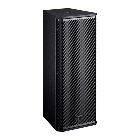
D.A.S. ARA Series User manual

ARA series
Users manual
www.dasaudio.com

2ARA series Users Manual
INDEX
INTRODUCTION
SYSTEM COMPONENTS
AMPLIFIER MODULES
POWER CONNECTORS AND POWER CONSUMPTION
AUDIO AND AUDIO&DATA CONNECTORS
DISPLAY OF THE UNIT AND CONTROL BUTTONS
DISPLAY AND NAVIGATION MENU
ARRAY BALANCE
ATMOS. CORRECTION
NETWORKING
ETHERNET RECOMMEDED SWITCHES / ROUTERS
ACCESSORIES
RIGGING
TROUBLESHOOTING
3
4
8
17
18
20
28
30
44
47

3ARA series Users Manual
ARA series
Introduction
Welcome to the user manual for the ARA series. This
comprehensive guide is designed to provide all the
information needed for the effective and safe operation
of our ARA systems.
This manual has been structured into several key sections,
each focusing on a specific aspect of system setup, usage,
and maintenance. By providing a detailed walkthrough of
each process, we aim to ensure that users can optimally
benefit from all features that our ARA systems offer.
The ‘Setup and Configuration’ section of this manual
will guide you through the initial stages of installing and
setting up your ARA system. It will delve into various
network configuration options, covering the use of
Ethernet switches and routers, with a focus on the DHCP
Server distribution.
In the ‘Hardware and Accessories’ section, we outline
recommended devices that complement and enhance
yourARAsystem’sperformance.Italsoprovidesguidelines
on how to choose suitable routers and Ethernet switches.
The ‘Rigging Procedures’ section emphasizes the
importance of safety and details the process of rigging
your ARA systems effectively. It provides a summary of
basic concepts related to rigging, though it is advisable to
refer to the rigging user’s manual for more comprehensive
information.
Lastly, the ‘Troubleshooting’ section provides insights into
diagnosing and resolving common issues that you may
encounter while operating the ARA system. From power
problems to sound issues, this section aims to assist you
in maintaining the system’s optimal performance.
Please read this manual thoroughly before using your ARA
system and refer to it as needed. Your understanding and
correct application of the information contained here are
critical to ensuring the best performance from the ARA
series.

4ARA series Users Manual
ARA series
System components
LARA-80 / LARA-100
LARA® is a 4-way symmetrical, cardioid, self-amplified line ar-
ray system with 6000Wrmspower. LARA® has a linear perfor-
mance of 146 dB SPL MAX and a wide dynamic range making it
an ideal system for large events. Thanks to the cardioid design,
we achieve a rear attenuation of -15 dB in the range of 63 Hz –
200 Hz.
LARA® incorporates 2 x 12″ woofers with a 4″ voice coil plus an-
other 2 x 8″ in cardioid configuration; for the midrange, it uses
another 2 x 8″ speakers with 2.5″ voice coils. The high-frequen-
cy section is made up of two DAS M-78N compression drivers,
with 3″ voice coils and a 100º or 80º horizontal dispersion wave-
guide. All the elements have been designed and purpose-built
to maximize the system’s efficiency.
The LARA® class D amplifier integrates a switching power sup-
ply with power factor correction (PFC), ensuring maximum per-
formance and efficiency regardless of the mains voltage. Each
amplifier provides 6000Wrmsdivided into eight channels,3 of
them in bridge mode to feed the 2 x 12″ and the two compres-
sion drivers. The remainingtwo channels feed the front 2 x 8″
and rear 2 x 8″ transducers.
The 3-point rigging system works for both LARA® and LARA®
SUB, allowing us to hang arrays of up to 24 LARA units and 16
LARA® SUB units. The FSS TM (Fast Set Splay) angulation sys-
tem allows angles to be adjusted in steps of 1º, from 0º to 7º from
the stacked position, significantly reducing assembly time.

5ARA series Users Manual
ARA series
System components
LARA-SUB
The LARA-SUB is a powered cardioid subwoofer system incor-
porating 2 DAS 18UXN neodymium low frequency transduc-
ers with 4” voice coils in a bass-reflex configuration. A single
rear-facing 18UXN is used to create the cardioid dispersion pat-
tern avoiding unwanted energy behind the system.
Powering the LARA SUB is a 3channel Class D amplifier with
independent channels powering each of the front-loaded low
frequency transducers and the rear facing cardioid speaker. The
amplifier´s regulated switch mode power supply is equipped
with power factor correction reducing power consumption
while enhancing reliability and consistency in all operating con-
ditions. The onboard DSP optimizes the signal parameters for
front and rear drivers to maximize the rear rejection 14 dB from
40 Hz – 80 Hz average.
Cabinet construction follows DAS´s strict construction stand-
ards employing birch plywood and the durable ISO-flexTM pro-
tective exterior coating. The LARA SUB incorporates captive rig-
ging hardware that makes use of the common LARA rigging
bumper, only one bumper type is needed to fly either LARA
ARRAY or LARA SUB. The protective metal grilles are backed
using acoustically transparent and water repellent fabric. Two
recessed handles are located on each side of the enclosure.

6ARA series Users Manual
ARA series
System components
SARA-100
SARA-100 is a compact line array system with a symmetrical
design and 3000Wrms of power, SARA delivers a linear perfor-
mance of 139 dB SPL MAX and a wide dynamic range, making it
perfect for events and medium-sized installations where sound
quality and uniformity are a priority.
SARA features two customized designed 8″ loudspeakers for
mid and low frequencies and a compression driver for high fre-
quencies with a 100° horizontal dispersion waveguide.
SARA’s Class D amplifier integrates a switch-mode power sup-
ply with power factor correction (PFC), ensuring optimum per-
formance and efficiency regardless of the mains voltage. The
amplifier provides 3000Wrms of power, divided into 4 chan-
nels, two of which are used in bridge mode to power the com-
pression driver, and the remaining two are used to power the 8″
front speakers.
The three-point rigging system can be used for both SARA and
SARA-SUB, allowing arrays of up to 24 SARA and 16 SARA-SUB
units to be hung. In addition, using the JP-SARA accessory,
up to 12 units of SARA can be hung below the SARA-SUB. The
FSS™ (Fast Set Splay) system allows angles to be adjusted in 1°
steps from the stacked position, significantly reducing assem-
bly time.

7ARA series Users Manual
ARA series
System components
SARA-SUB
SARA-SUB is a high-fidelity subwoofer that offers an accurate
and powerful bass response thanks to its cardioid design. The
system incorporates a DAS 18UXN neodymium loudspeaker
with a 4″ voice coil for excellent low-frequency reproduction.
In addition, a rear 15FWN neodymium 3″ voice coil speaker cre-
ates the necessary cardioid dispersion pattern to compensate
for unwanted energy in the rear.
The SARA-SUB’s built-in class D amplifier has 4 channels in
bridge mode for each of the speakers. The switch-mode power
supply has a correction factor, allowing for greater efficiency
and reliability under all operating conditions. The built-in DSP
optimizes the signal parameters for the loudspeakers and al-
lows for 14 dB of rear power compensation in the 40 Hz – 80 Hz
range.
The enclosure design meets the strict DAS standards for the
use of high-quality materials, such as birch plywood and ISO-
flex™ exterior protection. In addition, the rigging system allows
the SARA to be flown underneath the SARA-SUB, using the JP-
SARA. The metal grids incorporate acoustically transparent,
moisture-repellent fabric. Recessed handles on the sides of the
enclosure facilitate transport and handling.

8ARA series Users Manual
ARA series
Amplifier Modules
The ARA series is a family of self-powered products that includes
newest and most technologically sophisticated power packs in
the systems. A very powerful DSP platform working at 96kHz is
included allowing control and monitoring features. ALMA soft-
ware is the dedicated tool to adjust, control and optimize the
systems. Connectivity between the amplifier modules and the
control computer and ARA-RACKs is done using standard TCP/
IP data protocols.
POWER CONNECTORS and POWER CONSUMPTION
At the amplifier’s panel 2 powerCON true1 connectors (in and
loopthru) are used to inject power into the units and as well
linking power to other units.
The maximum number of units that can be linked in terms of
power depends on the consumption of each unit.
When working at 230/208V these are the limitations per system
model:
Please refer to the configuration documents to check connec-
tions between units.
AUDIO AND AUDIO & DATA CONNECTORS
Analog audio can be connected independently by using the
XLR Signal Input connector or in conjunction with control and
monitoring data by the use of the IN ethercon connector:
All amplifiers are including a 1.54” OLED display to provide cer-
tain level of configuration by the use of the control knobs (up/
down/back/enter) and checking information such as firmware
version.
Max number of linked
units (power)
LARA 2
LARA-SUB 2
SARA 4
SARA-SUB 3

9ARA series Users Manual
ARA series
Amplifier Modules
DISPLAY OF THE UNITS AND CONTROL BUTTONS
The display and control buttons of a SARA unit (LARA/LARA-SUB/
SARA-SUB use the same hardware) are shown below:
On the left side 4 different LEDs are located.
- The ON Led will lit in green when the unit is connected to mains.
- The COMMs Led will lit in orange when the system has been
connected to ALMA.
- The SIGNAL / LIMIT led will lit in green or red depending on the
signal level. Red shall represent limit status on at least one of
the channels of the system.
- The PROTECT Led will lit in red if an amplifier detects failure or
activates the protection mode.

10ARA series Users Manual
The Display shows the status of the system as follows (LARA and
SARA):
1. System Model
2. IP: Active when the system has obtained an IP address from a
DHCP server (router) or via Static configuration.
3. L/Sxxxx: ID name of the system. ALMA needs a unique ID name
per device. When systems are manufactured the amplifiers are
loaded with this unique ID number*.
4. Mute / Unmute: this symbol shows with a X on top of the speak-
er symbol if the system has been totally or partially muted by
using ALMA.
5. Device Gain: variations of Gain (level in dB) are possible from
+6dB to -40dB in 0.1 increments / decrements.
6. Device Delay: from 0ms to 323ms.
7. Array Balance settings. The graph shows both, AB Low and AB
High settings.
8. HPF filter: In case of “top” units such as SARA / LARA this part
of the display shows the active High Pass Filter (63/80/100Hz).
In case of subwoofer units, SARA-SUB / LARA-SUB, this part of
the display shows the active Low Pass Filter (LPF) 63/80/100Hz.
9. D EQ: When an equalization is active in the device (device EQ
or Global EQ on ALMA) this box will say D EQ. When no EQ is
applied the box appears empty.
ARA series
Amplifier Modules
10. HOS: High Order Shelving EQ. When a HOS equalization is
being active in the device (via ALMA), this box will say HOS.
When no EQ is applied the box appears empty.
11. DASaim: When the system has an active DASaim FIR filter
these lines appear in the box.
12. Atmos. Correction enabled: As sound propagates through
the atmosphere its energy is gradually absorbed by a num-
ber of energy-exchange processes in the air called atmos-
pheric absorption. To compensate this effect Atmos. Correc-
tion filter are appied at High frequencies depending on the
ambient conditions.

11ARA series Users Manual
1. System Model
2. IP: Active when the system has obtained an IP address from
a DHCP server (router) or via Static configuration.
3. L/Sxxxx: ID name of the system. ALMA needs a unique ID
name per device. When systems are manufactured the am-
plifiers are loaded with this ID number*.
4. Mute / Unmute: this symbol shows with a X on top of the
speaker symbol if the system has been totally or partially
muted by using ALMA.
5. Device Gain: variations of Gain (level in dB) are possible from
+6dB to -40dB in 0.1 increments / decrements.
6. Device Delay: from 0ms to 323ms.
7. LPF filter: In case of “top” units such as SARA / LARA this part
of the display shows the active High Pass Filter (63/80/100Hz).
In case of subwoofer units, SARA-SUB / LARA-SUB, this
part of the display shows the active Low Pass Filter (LPF)
63/80/100Hz.
8. D EQ: When an equalization is active in the device (device
EQ or Global EQ on ALMA) this box will say D EQ. When no
EQ is applied the box appears empty.
9. HOS: High Order Shelving EQ. When a HOS equalization is
being active in the device (via ALMA), this box will say HOS.
When no EQ is applied the box appears empty.
ARA series
Amplifier Modules
*ID numbers:
SARA-100 units are named as S20xxxx.
LARA-100 units are named as L20xxxx.
LARA-80 units are named as L10xxxx.
LARA-SUB units are named as L30xxxx.

12ARA series Users Manual
ARA series
Amplifier Modules
The user can have access to different settings in the units
using the control buttons (back / enter / up /down) and the
display located at the amplifier’s panel:
SARA Display and control buttons.
When pressing BACK, the system is
LOCKED (the display will turn Off)
When pressing DOWN, some rapid in-
formation is show, IP Address and De-
vice ID:
When pressing ENTER, the user access
to the MAIN MENU and configuration
parameters:

13ARA series Users Manual
ARA series
Amplifier Modules
DISPLAY AND MAIN MENU
The Main Menu allows the user to access
the following sub-menus: Configuration /
Utilities / Information / Default Parameters
1. Configuration Sub-menu:
Shown in red the possible values of each parameter.

14ARA series Users Manual
ARA series
Amplifier Modules
DISPLAY AND MAIN MENU
The Main Menu allows the user to access
the following sub-menus: Configuration /
Utilities / Information / Default Parameters
2. Utilities Sub-menu:

15ARA series Users Manual
ARA series
Amplifier Modules
DISPLAY AND MAIN MENU
The Main Menu allows the user to access
the following sub-menus: Configuration /
Utilities / Information / Default Parameters
3. Information Sub-Menu:

16ARA series Users Manual
ARA series
Amplifier Modules
3. Default Parameters Sub-Menu: When confirming default parameters in a unit, all
these parameters are modified:
AB LO Set to 0
AB HIGH Set to 5
HPF Set to 63Hz
LPF Set to 63Hz
Device Gain Set to 0dB
Device Delay Set to 0dB
DASaim Filters Erased
Global EQ/ Device EQ / HOS EQ Erased
Channel SOLO / Device SOLO Erased
Channel Mute / Global Mute / Device Mute Erased

17ARA series Users Manual
ARA series
Array Balance
To compensate the acoustical coupling between elements of a
line array system, two main parameters have been implement-
ed in the units. The “target” frequency response of the entire
system will be defined by the use of these 2 parameters.
Shown below, the average frequency response trace of a 12 el-
ement Lara system, measured with 3 microphones in different
positions.
In this particular case AB Low was set to -4, and AB High was
set to 4. The acoustical target response obtained with these 2
values had a lot of energy in the low-mid frequency domain as
it was required for the application.
ARRAY BALANCE LOW (steps of 1dB):
Low Shelving filters starting at 400Hz with 8 different values in gain.
Array Balance Low 0: 0dB
Array Balance Low -1: -1dB
Array Balance Low -2: -2dB
Array Balance Low -3: -3dB (shown in the graph above)
Array Balance Low -8: -8dB
ARRAY BALANCE HIGH (steps of 1dB):
High Shelving filters starting at 1490Hz with 8 different values in gain.
Array Balance High 0: 0dB
Array Balance High 1: 1dB
Array Balance High 2: 2dB
Array Balance High 3: 3dB
Array Balance High 8: 8dB
In SARA and LARA systems the “default parameters” are Array
Balance Low 0, Array Balance High 5.
To obtain a flat frequency response of one unique system (device)
to be used for instance as a front fill, the user shall use Array
Balance Low 0, Array Balance High 0.

18ARA series Users Manual
As sound propagates through the atmosphere its energy is
gradually absorbed by a number of energy-exchange process-
es in the air called atmospheric absorption.
The degree of absorption depends on the frequency of the
sound wave and the composition of the atmosphere.
At low frequencies, sound waves are generally not absorbed by
the atmosphere and can travel long distances. However, as the
frequency increases, the atmosphere becomes more effective
at absorbing sound. This is because the air molecules them-
selves start to absorb some of the sound energy.
In most conditions, dry air can produce high attenuation of
sound at high frequencies. Therefore, in the case of a predom-
inantly high-frequency range, measurements made under dry
conditions can differ considerably from measurements made
under more humid conditions.
The compensation of the absorption of sound by air (humidity
and temperature) implemented on ALMA is based in the ISO
9613-1: 1993 “Attenuation of sound during propagation outdoors
-Part 1: Calculation of the absorption of sound by atmosphere”.
For each ARA system, SARAs and LARAs the atmospheric cor-
rection can be activated independently per unit considering the
target distance of it and the ambient conditions (air tempera-
ture and humidity). ALMA includes a family of more than 500
filters that are activated at different frequencies with different
gain levels depending on the distance and ambient conditions.
For example, shown above the air absorption at 25ºC - 55% rel-
ative humidity. A percentage of correction parameters is pre-
sented:
ARA series
Atmos. Correction

19ARA series Users Manual
WhenEnabled,Atmos.Correctioncanbeactivatedindependently
per unit or per group of units:
Shown below 4x LARA-80 on top of the array (12 units) with 2
different corrections (40m to 60m and 20m to 40m).
The Atmos. correction is activated ON ALMA, not via
display of the units. Atmos. Correction - parameters
window on ALMA:
ARA series
Atmos. Correction

20ARA series Users Manual
INTRODUCTION
ARA series systems communicate using standard TCP/IP data
protocols. As professional audio equipment it is almost manda-
tory the use of ARA products with compatible professional net-
work hardware. Gigabit switches can be found in the industry
in a very wide range of prices and features but always keep in
mind that domestic intended hardware may not perform prop-
erly as there exist limitations managing network bandwidths
and impossibility of managing a big number of devices.
The quality of the network cabling used is also a key factor to
not face problems specially when dealing with distances close
to the limit (100meters) and big bandwidths. As a general rule
only use CAT6e or CAT7 cabling with the proper shielding.
Ethernet cables are used to transmit data between network de-
vices, such as computers, routers, and switches. Both Cat6e and
Cat7 cables are types of Ethernet cables that are designed to
support high-speed data transfer rates and reduce signal inter-
ference. However, there are some differences between the two:
ARA series
Networking
1. Bandwidth: Cat6e cables are designed to support band-
widths of up to 500 MHz, while Cat7 cables can support up
to 600 MHz. This means that Cat7 cables have a higher ca-
pacity for transmitting data at faster speeds.
2. Shielding: Cat6e cables usually have shielding around each
pair of twisted wires to reduce crosstalk (interference be-
tween wires). On the other hand, Cat7 cables have individu-
al shielding around each pair of twisted wires, as well as an
overall shielding around all four pairs. This provides better
protection against crosstalk and external electromagnetic
interference.
3. Connectors: Cat6e cables use the same RJ45 connectors as
most other Ethernet cables, while Cat7 cables use a different
type of connector called GG45, which is designed to support
higher frequencies and reduce crosstalk.
4. Distance: Both Cat6e and Cat7 cables can transmit data over
distances of up to 100 meters (328 feet), but Cat7 cables are de-
signed to maintain their signal quality over longer distances.
Overall, Cat7 cables are a more advanced and expensive op-
tion than Cat6e cables, and are typically used in high-perfor-
mance network environments that require very high band-
widths and reliable transmission of data over long distances.
Cat6e cables are a more affordable and widely used option for
many standard Ethernet applications.
It’s important to note that the maximum distance is 100m
(328feet) for a single ethernet CAT6e cable (for 10 Gbps speeds)
segment without any repeaters or switches in between. If you
need to extend the distance beyond these limits, you can use
repeaters, switches, or fiber optic cables to extend the reach of
your Ethernet network.
This manual suits for next models
2
Table of contents
Other D.A.S. Speakers System manuals
D.A.S.
D.A.S. Sound Froce SF-158 User manual
D.A.S.
D.A.S. AERO-12A User manual
D.A.S.
D.A.S. ST Series User manual
D.A.S.
D.A.S. EVENT SERIES User manual
D.A.S.
D.A.S. EVENT-208A Quick start guide

D.A.S.
D.A.S. AXS-40UX User manual
D.A.S.
D.A.S. Sound Force SF-112 User manual
D.A.S.
D.A.S. AERO-38 series User manual

D.A.S.
D.A.S. Aero 2 Series Quick start guide
D.A.S.
D.A.S. arco 4 User manual

