d & b audiotechnik Ti10 User manual

Ti10
Manual 1.1 en

Symbols on the equipment
Please refer to the information in the operating manual.
WARNIN !
Dangerous voltage!
Contents
Safety precautions..............................................................3
Information regarding use of loudspeakers............................................3
Ti10....................................................................................4
Ti-Series rigging components and arrays................................................4
Ti10L, Ti10P ca inet options...................................................................5
Connections..............................................................................................6
Operation.................................................................................................6
Dispersion characteristics........................................................................8
Technical specifications...........................................................................9
Manufacturer's Declarations.............................................10
EU conformity of loudspeakers (CE sym ol)........................................10
WEEE Declaration (Disposal)...............................................................10
eneral Information
Ti10 Manual
Version 1.1 en, 03/2016, D2602.EN .01
Copyright © 2016 y d& audiotechnik Gm H; all rights reserved.
Keep this manual with the product or in a safe place so that it is availa le
for future reference.
When reselling this product, hand over this manual to the new customer.
If you supply d& products, please draw the attention of your customers
to this manual. Enclose the relevant manuals with the systems. If you
require additional manuals for this purpose, you can order them from
d& .
d& audiotechnik Gm H
Eugen-Adolff-Strasse 134, D-71522 Backnang, Germany
Telephone +49-7191-9669-0, Fax +49-7191-95 00 00
E-mail: docadmin@d audio.com, Internet: www.d audio.com

Safety precautions
Information regarding use of loudspeakers
WARNIN ! Never stand in the immediate vicinity of loudspeakers driven at a high
level. Professional loudspeaker systems are capa le of causing a sound
pressure level detrimental to human health. Seemingly non-critical sound
levels (from approx. 95 dB SPL) can cause hearing damage if people are
exposed to it over a long period.
In order to prevent accidents when deploying loudspeakers on the ground
or when flown, please take note of the following:
When setting up the loudspeakers or loudspeaker stands, make sure they
are standing on a firm surface. If you place several systems on top of one
another, use straps to secure them against movement.
Only use accessories which have een tested and approved y d& for
assem ly and mo ile deployment. Pay attention to the correct application
and maximum load capacity of the accessories as detailed in our specific
“Mounting instructions” or in our "Flying system and Rigging manuals".
Ensure that all additional hardware, fixings and fasteners used for
installation or mo ile deployment are of an appropriate size and load
safety factor. Pay attention to the manufacturers' instructions and to the
relevant safety guidelines.
Regularly check the loudspeaker housings and accessories for visi le
signs of wear and tear, and replace them when necessary.
Regularly check all load earing olts in the mounting devices.
CAUTION! Loudspeakers produce a static magnetic field even if they are not
connected or are not in use. Therefore make sure when erecting and
transporting loudspeakers that they are nowhere near equipment and
o jects which may e impaired or damaged y an external magnetic
field. Generally speaking, a distance of 0.5 m (1.5 ft) from magnetic data
carriers (floppy disks, audio and video tapes, ank cards, etc.) is
sufficient; a distance of more than 1 m (3 ft) may e necessary with
computer and video monitors.
Ti10 Manual (1.1 en) Safety precautions - 1
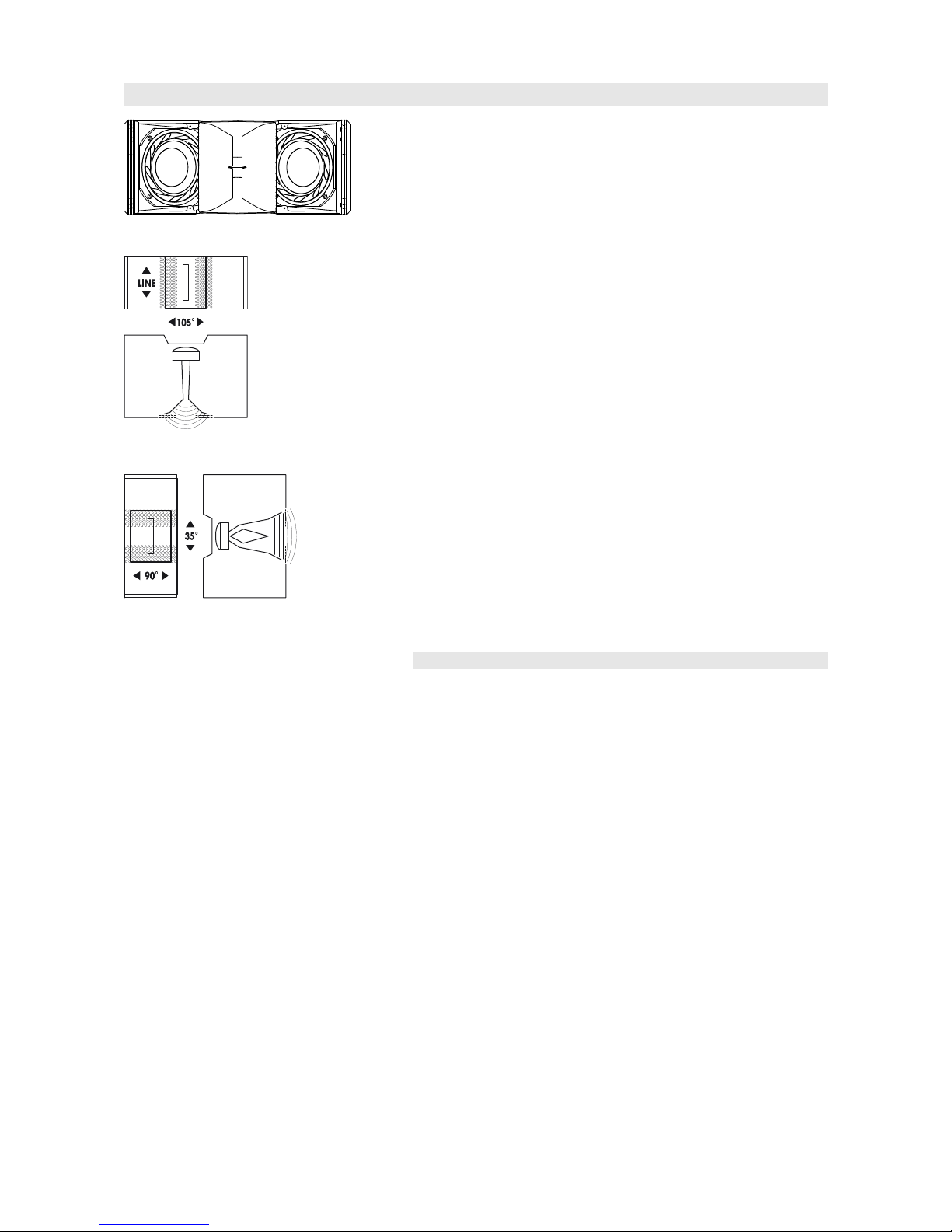
Ti10
Fig. 1: Ti10 loudspeaker
Fig. 2: Ti10 Horn and lens
in line source setup
Fig. 3: Ti10 Horn and lens
in point source setup
The Ti10 is the installation version of the T10 loudspeaker. It is a very
compact loudspeaker system which can e used oth as a line array and
as a high directivity point source speaker. For these applications the Ti10
ca inet provides two different dispersion characteristics which can e
swapped over without any tools.
The core of the design is a unique com ination of a rotata le waveguide
with horn and an acoustic lens. The horn natively provides a vertical line
source with 90° horizontal dispersion. The lens is part of the front grill
and widens the HF dispersion in line array mode to 105°. When used
upright as a point source, the lens curves the wavefront of the line source
providing a 90° x 35° dispersion pattern.
The Ti10 is a two way design employing dual 6.5” drivers, a 1.4” exit
compression driver and a passive crossover network. The low drivers are
positioned in a dipolar arrangement providing an exceptional dispersion
control towards low frequencies. Its frequency response extends from
68 Hz to a ove 18 kHz.
The Ti10 enclosure is constructed from polyurethane integral hard foam
with an impact and weather resistant lack paint finish. The ca inet shape
allows the system to e set up as a single unit in upright orientation or as
a line array in user defined vertical configurations. The front of the
loudspeaker ca inet is protected y a rigid metal grill in front of an
acoustically transparent foam.
Ti-Series rigging components and arrays
For line and point source applications the Ti10 loudspeaker is availa le in
two different ca inet versions which are acoustically identical:
-Ti10L: Line source version including line array rigging devices. It can
e used as a line array and as a stand-alone loudspeaker with oth
horn orientations.
-Ti10P: Point source version without line array rigging devices. It can
e used as a stand-alone loudspeaker with oth horn orientations.
For line array applications Ti10L ca inets are mechanically connected
using the rigging strands on oth sides of the ca inet front and a central
strand at the rear of the ca inet. All necessary rigging components are
mounted to the ca inet and are folded or slide out when needed. Splay
angles etween adjacent ca inets can e set in the range from 0° to
15°.
For point source applications oth the Ti10L and Ti10P are fitted with six
threaded inserts to connect to different rigging accessories like Z5371 T
Flying racket, Z5372 T Horizontal racket, Z5354 E8/E12 Flying
adapter or Z5020/25 Flying adapter 02/03.
Ti10 Manual (1.1 en) Page 4 of 10

Ti10L rigging procedure
1
2
4
3
Fig. 4: Assembly of a Ti10L line array
Ti10L line arrays are set up using the Z5370 T Flying frame. The rigging
procedure follows the description given in the T-Series Rigging manual
which is provided with the T Flying frame. However, Ti10L and T10
ca inets have different front rigging mechanisms. The Ti10L front rigging is
equipped with hooks and fixed olts instead of locking pins and hidden
ehind a cover in ca inet color.
To attach a Ti10L ca inet to an array or to the T Flying frame, proceed as
follows:
1. Slide out the Front links and the Splay link of the ca inet.
2. Set the Locking pin at the rear rigging of the upper
ca inet/frame to the desired position (splay angle).
3. Keep the ca inet at an angle of 90° to the upper
ca inet/frame.
4. Insert the Front links into the front rigging of the upper ca inet
(1)
5. Slowly lower the ca inet and make sure the hooks rest in the
olts (2).
6. Lift the ack of the ca inet (3) and hook the Splay link over the
preset Locking pin of the upper ca inet/frame (4).
7. Insert the second Locking pin (safety pin) to secure the Splay link
of the ca inet.
Ti10L line arrays of up to 3 ca inets can e supported with the
Z5373 T Cluster racket which allows an easy aiming of the array either
flown or mounted on a high-stand.
A detailed description of planning and designing T-Series arrays is given
in the technical information "TI 385 Line array design, ArrayCalc" which
is also provided with the T Flying frame. The d& ArrayCalc simulation
software can e downloaded from the d& we site at
www.d audio.com.
Ti10L, Ti10P cabinet options
The special color (SC) version of the ca inet is availa le in all colors of
the RAL color ta le. The connector type is NL4.
The weather resistant (WR) version is availa le in lack only. It is
equipped with a fixed input ca le.
NOTICE: The WR option ena les operation of loudspeakers in
changing am ient conditions, however it is not intended to
ena le permanent, unprotected operation of loudspeakers
outdoors.
-Provide an additional cover over the loudspeakers.
-Aim the ca inets either horizontally or with a downward
tilt.
Ti10 Manual (1.1 en) Page 5 of 10

Connections
1+
1-
2+
2-
1+
1-
2+
2-
passive
crossover
Fig. 5: Connector wiring
The Ti10 ca inet is fitted with a pair of NL4 connectors. All pins of oth
connectors are wired in parallel. The Ti10 uses the pin assignments 1+/
1–. Pins 2+/2–are designated to active su woofers. Using one
connector as the input, the second connector allows for direct connection
to additional loudspeakers.
The weather resistant (WR) version of the Ti10 is equipped with a fixed
input ca le (5 m / 16.4 ft, type H-07-RN-F 2 x 2.5 mm2/AWG 13).
Pin equivalents of NL4 connectors and the fixed ca le option are listed in
the ta le elow.
NL4 1+ 1–2+ 2–
Fixed cable (P ) Brown (+) Blue (–)
Operation
NOTICE!
Only operate d& loudspeakers with a correctly configured d&
amplifier, otherwise there is a risk of damaging the loudspeaker
components.
Applicable d&b amplifiers:
D80/D20/D12/D6/10D/30D.
Application Setup Cabinets per channel
Ti10L T10 Arc / T10 Line 4
Ti10P T10 PS 4
The applica le d& amplifiers provide three setups ("Arc", "Line" or “PS”)
for the Ti10 loudspeaker. These are availa le in Dual Channel or Mix
TOP/SUB mode.
"T10 Arc" and "T10 Line" setups
These setups are selected when Ti10L loudspeakers are used. The
selection depends on the curvature of the array. Both setups may e used
within one array.
The "Arc" setup is used for Ti10L loudspeakers when used in curved array
sections.
The "Line" setup is used for long throw array sections with three or more
consecutive splay settings of 0°, 1°or 2°. Compared to the "Arc" setup,
the upper mid range is reduced to compensate for the extended near
field.
The transition from "Line" to "Arc" configuration within the array is made
according to the splay progression ut may allow for certain deviations
due to the wiring of the ca inets in groups of up to four.
"T10 PS" setup
This setup has to e selected when Ti10 loudspeakers are configured as a
point source or when used as single ca inets with horn in line array
configuration (e.g. front fill or ceiling mounted).
Ti10 Manual (1.1 en) Page 6 of 10

Controller settings
For acoustic adjustment the functions CUT, HFA, HFC and CPL can e
selected.
CUT circuit
Set to CUT, the Ti10 low frequency level is reduced. The Ti10 is now
configured for use with the Ti-SUB or other d& active su woofers.
HFA circuit (T10 PS setup only)
-5
0
5
10
-10
-15
-20
-25
-30
20 100 1k 10k 20k
Fig. 6: Frequency response correction of
HFA circuit
In HFA mode (High Frequency Attenuation), the HF response of the Ti10
system is rolled off. HFA provides a natural, alanced frequency response
when a unit is placed close to listeners in near field or delay use.
High Frequency Attenuation egins gradually at 1 kHz, dropping y
approximately 3 dB at 10 kHz. This roll-off mimics the decline in
frequency response experienced when listening to a system from a
distance in a typically rever erant room or auditorium.
HFC circuit (T10 Arc/Line setups only)
Fig. 7: Frequency response correction of HFC
circuit
Selecting the HFC (High Frequency Compensation) circuit compensates
for loss of high frequency energy due to a sorption in air when
loudspeakers are used to cover far field listening positions.
The HFC circuit has two settings (HF1, HF2) for different distance ranges
the ca inets have to cover. The settings should e used selectively, only
for those ca inets covering the respective distances, HF1 for distances
larger than 25 m (80 ft) and HF2 for distances larger than 50 m (160 ft).
The compensation is adjusted for a typical relative humidity of 40 %. With
lower humidity the a sorption y air increases therefore the distances
where the respective HFC setting provides a correct equalization are
shorter than indicated a ove.
Using the HFC function provides the correct sound alance etween close
and remote audience areas, whilst all amplifiers driving the array can e
fed with the same signal.
CPL circuit
Fig. 8: Frequency response correction of CPL
circuit
The CPL (Coupling) circuit compensates for coupling effects etween the
ca inets; these effects increase as the length of the line array is extended.
CPL egins gradually at 1 kHz, with the maximum attenuation elow
400 Hz, providing a alanced frequency response when Ti10 ca inets
are used in arrays of four or more. The function of the CPL circuit is shown
in the diagram opposite and can e set in dB attenuation values etween
–9 and 0, or a positive CPL value which creates an adjusta le low
frequency oost around 65 Hz (0 to +5 dB).
Note: Make sure that all ca inets within the line array are operated
with the same CPL setting.
Ti10 Manual (1.1 en) Page 7 of 10

Dispersion characteristics
The graphs elow show dispersion angle over frequency of a single Ti10
ca inet plotted using lines of equal sound pressure (iso ars) at – 6 dB
and –12 dB.
Fig. 9: Isobar diagram Ti10 line source, horizontal Fig. 10: Isobar diagram Ti10 line source, vertical
Fig. 11: Isobar diagram Ti10 point source,
horizontal
Fig. 12: Isobar diagram Ti10 point source, vertical
Ti10 Manual (1.1 en) Page 8 of 10

Technical specifications
Fig. 13: Ti10 frequency response
line source, single cabinet,
standard and CUT settings
Fig. 14: Ti10 frequency response
point source, standard and CUT settings
Ti10 system data
Frequency response (–5 dB standard)............................................68 Hz ... 18 kHz
Frequency response (–5 dB CUT mode).......................................120 Hz ... 18 kHz
Max. sound pressure (Line/Arc setups, 1 m, free field)..............................................
with D6/10D....................................................................................................129 dB
with D80/D20/D12/30D..............................................................................132 dB
Max. sound pressure (PS setup, 1 m, free field)..........................................................
with D6/10D....................................................................................................127 dB
with D80/D20/D12/30D..............................................................................130 dB
(SPLmax peak, pink noise test signal with crest factor of 4)
Input level (100 dB-SPL/1 m)........................................................................–13 dBu
Ti10L/P loudspeaker
Nominal impedance......................................................................................16 ohms
Power handling capacity (RMS / peak 10 ms).....................................200/800 W
Nominal dispersion angle (point source, hor. x vert.)...............................90° x 35°
Nominal dispersion angle (line array, horizontal).............................................105°
Splay angle settings................................................................0...15° (1° increment)
Components................................................2 x 6.5“ driver with neodymium magnet
................................................................1.4” exit compression driver on waveguide
............................................................................................Passive crossover network
Connections.....................................................................................................2 x NL4
..............WR option: Fixed ca le 5 m (16.4 ft) (H-07-RN-F 2 x 2.5 mm2/AWG 13)
Pin assignments........................................................................................NL4: 1+/1–
.....................................................................................Fixed ca le: Brown + / Blue –
Weight.......................................................................11 kg (24 l ) / 10.5kg (23 l )
Fig. 15: Ti10L/P cabinet dimensions in mm [inch]
Ti10 Manual (1.1 en) Page 9 of 10

Manufacturer's Declarations
EU conformity of loudspeakers (CE symbol)
This declaration applies to
Ti10L loudspeaker, Z0551
Ti10P loudspeaker, Z0552
manufactured y d& audiotechnik Gm H.
All production versions of these types are included, provided they
correspond to the original technical version and have not een su ject to
any later design or electromechanical modifications.
We herewith declare that said products are in conformity with the
provisions of the respective EC directives including all applica le
amendments.
A detailed declaration is availa le on request and can e ordered from
d& or downloaded from the d& we site at www.d audio.com.
WEEE Declaration (Disposal)
Electrical and electronic equipment must e disposed of separately from
normal waste at the end of its operational lifetime.
Please dispose of this product according to the respective national
regulations or contractual agreements. If there are any further questions
concerning the disposal of this product please contact d& audiotechnik.
D2602.EN .01, 03/2016 © d& audiotechnik Gm H
d&b audiotechnik mbH, Eugen-Adolff-Str. 134, D-71522 Backnang, ermany, Phone +49-7191-9669-0, Fax +49-7191-95 00 00_______
Other manuals for Ti10
1
Table of contents
Other d & b audiotechnik Speakers System manuals


