Genelec 1029A User manual
10294 Operating
Manual
Genelec
1029A
Active
Monitoring
System
GENELECg,'"
4o /,te,H- FkA', 6o re n

GENELEC'
1029A
ActiveMonitoring
System
Generaldescription
Thebi-amolifiedGENELEC10294isa two
way
activemonitoring
speakerdesignedtobe
smallbutstillhavehigh
output,
low
coloration,
andbroadbandwidth.
The10294is
idealfornearfieldmonitoring,
mobile vans, broadcast and TV control
rooms, surround sound systems, budget
homestudios,multimedia
applicationsand
also for use with comouter soundcards.
As an active speaker,it containsdrivers,
power
amplifiers,
activecrossoverfiltersand
protection
circuitry.The Directivity
Control
WaveguiderM
(DCWTM)
technology used
provides
excellentfrequencybalance in
difficultacousticenvironments.lf necessary,
the bass resoonse
of the 1029A's
can be
extendedwith a Genelec7050A or 70604
subwoofer.
Integrated
Construction
As the amplifiersarebuiltintothespeaker
enclosure,theonlyconnectionsrequired
are
the mainssupply
and the line level
input
signal,makingthe 10294very
easyto set
upanduse.Theintegrated
designallowsthe
amplifiersandthedriversto becalibratedas
asingle
unitatthefactory.Thiseliminatesthe
effectsofcomponenttolerances
andensures
consistent
quality.
Thecastaluminium
cabinet
has roundedcorners and a hard-wearino
painted
outer
surface.
Drivers
The bassfrequenciesare reproduced
by a
130mm (5")
bassdriver
mounted
in a 4.5
litrevented
cabinet.The -3 dB ooint
lies
at
68 Hz and thefrequencyresponse
extends
downto65 Hz(-6
dB).
The highfrequency
driveris a 19 mm
(3/4")
metaldome.
Uniformdispersioncontrol
is achieved with the revolutionaryDCW
Technology
pioneered
by
Genelec,
whichhas
also resultedin perfect phase and delay
uniformityatthecrossover
frequency.
Magnetic
shieldingis standardon the
10294.Shieldingis vital for applications
suchas videopostproduction,
where
stray
magneticfieldsmust
be
minimized.
Crossover
Theactive
crossover
network
consistsoftwo
parallel
bandpassfilters.Acoustically,thefil-
tersarecomplementaryandthe
slopesare
24- 32 dBloctave.Thecrossoverfrequency
is 3.3 kHz.The active crossovercontrols
('treble
tilt',
'bass
tilt'and'bassroll-off')
allow
this speaker
to be exactlymatchedto any
application.
Amplifiers
The amplifierunitis built
into
the speaker
enclosure.The bass and trebleamolifiers
both
produce
40W ofoutput
power.
Thefast,
low
distortionamplifiersare capableof driv-
ing
a stereo
pair
to peak
outputsound
pres-
surelevelsinexcessof 110dBat 1 m.The
unit
incorporates
specialcircuitryfordriver
overload
protection.
Variableinput
sensitivity
allowsforaccuratelevelmatchino.
Installation
Each10294
monitorissuppliedwithaninte-
grated
amplifierunit,mainscable
and an
operatingmanual.Afterunpacking,
place
the
loudspeaker
initsrequiredlistening
position,
taking
note
of the lineof the listening
axis
(see
Figure1).Before
connectingup,ensure
thatthemainsswitchisoff
andthe
volume
control
fully
counter-clockwise
(see
Figure1).
Checkthatthemainsvoltage
selector
iscor-
rectlyset
(models
soldinEuropehave
afixed
230V
setting).
Audioinput
isviaa 10kOhm
balancedXLRconnector
ora 10kOhm
bal-
anced
1
14"Jack.An unbalancedsourcemay
beusedaslongaspin
3 is
grounded
topin1
attheinput
(see
Figure2).Oncetheconnec-
tionhasbeenmade,thespeakersareready
to beswitchedon.
Setting
thevolume
control.
The input
sensitivityof the speakerscan be
matched
to the outputofthe mixingdesk
or
othersourcebyadjustingthevolume
control
onthefront
panel(see
Figure1).
Settingthetonecontrols
Theresponse
of
the
systemusuallyhastobe
adjustedto matchtheacousticenvironment.
The adiustmentis doneby settingthe tone
controlswitchesonthe rearDanel.
Thetone
control has four switchesand can adjust
'treble
tilt',
'bass
tilt'and'bass
roll-off.'The
factory
settings
for these are 'ALL OFF'to
givea flat anechoic
response.
SeeTable1
for suggestedtonecontrolsettingsin differ-
ing
acousticenvironments.
Figure4 shows
the effectof the controlson the anechoic
response.Always
startadjustmentbysetting
allswitches
to 'OFF'
oosition.
Thensetthe
switch
ifneeded
tothe'ON'oosiiion
toselect
theresponsecurveneeded.
Monitor
placement
Consoletopmounting
lfthe 10294's
areused
fornearfieldmoni-
toring,avoidmountingthemdirectlyonthe
consoletop. Instead
position
the speakers
slightlybehindthe consoleby usingfloor
stands,
wallmounts
or microphonestands.
Thisminimisesthe reflection
from
thecon-
solesurface
from
colouring
thesound.
Room placement
Itisvitalthatthemonitorsareconectly
posi-
tioned
in
theroomasthis
greatly
affects
their
performance.
To
produce
atrue
andaccurate
stereoimagethemonitorsmusthaveexactly
similarfrequencyresponses,
whichistrue
infreefieldconditions.Thefrequencycharts
shownare for free fieldconditions.
When
placed
ina roomtheresponsechangesdue
to reflectionsol the wavefrom the room's
boundaries.ltisthereforenecessary
toplace
the monitors
at thesameheightandalsoat
the same distancefrom the front and side
wallsso that the reflections,and therefore
thechangesto thefrequency
response,are
thesame.
Thedistancefromthefrontwall
should
be
eitherlessthan 1 m, or alternatively
more
than 3 m to avoid an uneven frequency
response
due to retlectionsfrom the wall.
lf the speaker
is placed
closeto the wall
(<1m)thiswillboost
the lowerfrequencies
and
thetone
controlsshould
thenbeadiusted
appropriately
(see
Table1).
The monitorsshouldbe aimedtoward
the
listening
position.
Thisis dueto the effectof

GENELEC'
Figure
1: 1029A's
outerdimensions,
with
the reference
axisbetween
the bassand
lhe trebledrivers.
RCA
Figure
2:Typeof
cable
needed
i{
unbalanced
source
is
used
(example
shown
isRCAoutput
to
theXLR
input)
the DCW which increases
the directivity.
lf
the ratioof direct
sound
to reflected
sound
is greater
thelistener
isthenable
to listen
to more of the material and less of the
roomeffects.
Subiectively
this
is
perceived
as
superior
stereo
imaging.
Mounting
options
The 1029Aof{ers
several
mounting
options:
On the base
ol the monitor
is a 3/8"
UNC
threaded
holewhichcan accommodate
a
standard
microphone
stand.
On the rear
there
isa provisionior anOmnimount@,
size
50, bracket,
the hardware
required
is two
M6x'lOmm
screws.
Alternatively,
thespeaker
canbehungonawall
inavertical
orhorizon-
talposition
byoneof thethree
wallhanging
points.
A setof friction
padsis also provided
for
placing
the10294on
flatsurfaces.
Maintenance
No user serviceable
partsare to be found
withinthe amplifier
unit.
Any maintenance
or repairof the 10294unit
should
only
be
undertaken
by
qualified
service
personnel.
should
be
observed:
. Donotuse
this
product
withanunearlhed
speakers.
Guarantee
Table1: Suggested
tonecontrol
settings
lor differing
acouslical
environments
Safety Considerations ' Thisequipment
iscapable
of
producing
Arthough
the
102eA
r.'u,u"* desisned
in l,il:lTT'::':"i"H:::T"[il":;
accordance
with international
safety
stand- damage.
ards.toensuresaleoperationandtomain..Freef|owofairbehindthe|oudspeakeris
tain
the
instrument
under
safeoperating
con- necessary
to maintain
sufficient
cooling.
ditions,
thefollowing
warnings
andcautions Do not
obstruct
airflow
around
the loud-
mains
cable
asthis
maycompromise
elec- This product
is guaranteed
for a periodof
tricalsafety. ONE
year
against
faults
inmaterials
orwork-
. Do not expose
the loudspeaker
to water manship.
Refer
to supplier
forfullsalesand
or moisture.
Do not place any objects guarantee
terms.
filledwith liquid,
such as vaseson the
loudspeaker
ornear
it.
Speaker
Mounting
Position Treble
Tilt Bass
Tilt Bass
Roll-Otf
Flat
Anechoic
ResPonse OFF OFF OFF
Free
standing
ina damPed
room OFF OFF OFF
Freestanding
ina reverberant
room OFF -2dB OFF
Near
fieldon
console
bridge OFF -4
dB OFF
Near
toawall OFF -6
dB OFF
Witha7050A
or1091A
subwoofer Seeabove
settings See
above
settings ON
Switch1: Treble
Tilt
Switch2: Bass Roll-Off
Switches3&4: BassTllt
TONE
CONTROL VOLTAGE
SELECTOR
E/^
f tftf lt I
|ilililte!- (( \rli
l-ll-ll-ll-r()FF \\ V 7/
Eilluq v
BASS AND TREBLE TILT BASS ROLL-OFF
fF;IsEmil
lilS
,Q.
"uu-
| GENEI.EC
230
V- | ACTTVE
MONITOR
50/60
Hz
I rvrooer_
.t029A
dB
0
-2
-6
|NPUT2 (1/4) / SUB
OUT
Figure3: Control
andconnector
layout
onthe
rear
panel
oi a 10294
1029A
Operating
Manual
MO mEOSTON r@9ffi 23sEP96 10:24:33
lm
95
85
a0
75
70
65
60
55
$
Ap
,ASSTILI Nr
BASSROL
t[
t#l
tok 201
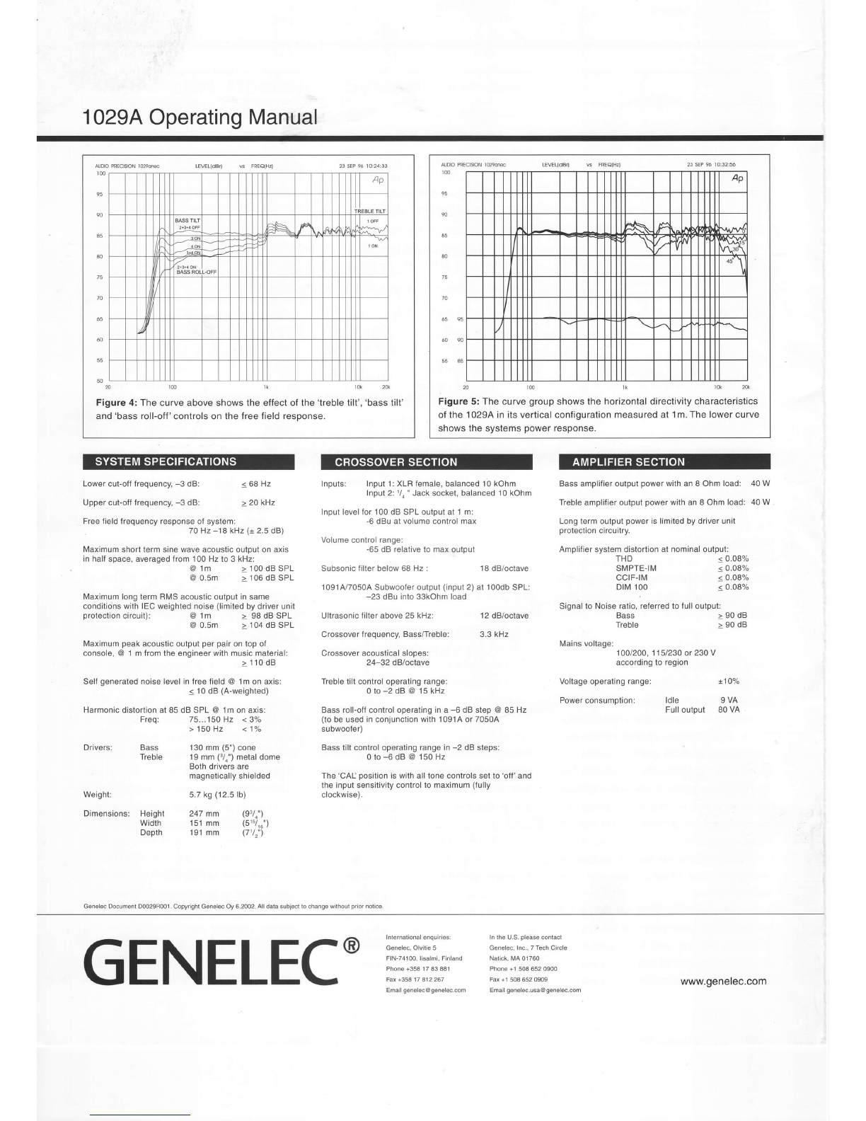
Figure 4: The curveaboveshowsthe effectof the'lreble tilt',
'bass
tilt'
and'bassroll-off'controlsonthefreefieldresoonse.
ruoo PRECISPNlono@
to0 23SEP
t6 tO:32:56
70
65 95
55 A5
.2Otmlkr&2ft
Figure 5:Thecurve
group
showsthe horizontaldirectivitycharacteristics
of the 1029A
in itsverticalconfiguration
measuredat 1m.Thelowercurve
showsthe systems
power
response.
Lowercut-offfrequency,
-3 dB: < 68Hz
Uppercut-offfrequency,
-3 dB: > 20 kHz
Freefieldfrequencyresponseof system:
70 Hz -18 kHz(j 2.5
dB)
Maximumshorttermsinewaveacousticoutputonaxis
inhalf
space,averagedfrom100 Hzto 3 kHz:
@
lm >100dBSPL
@0.5m > 106dBSPL
MaximumlongtermRMSacousticoutputinsame
conditionswithIECweightednoise
(limited
bydriverunit
Inputs: Input1:XLRfemale,balanced10kohm
Input2:1/a"Jacksocket,balanced10kohm
Inputlevellor 100dB SPLoutputat 1 m:
-6dBuatvolumecontrolmax
Volume
control
range:
-65
dB relativeto max
output
Subsonic
lilterbelow68 Hz: 18dB/octave
1
091
A/7050A
Subwooler
output
(input
2)at 100db
SPL:
-23 dBuintos3kohm load
Ultrasonicfilterabove
25kHz: 12
dB/octave
Crossover
frequency,Bass/Treble: 3.3kHz
Crossoveracousticalslopes:
24-32 dBloclave
Trebletiltcontroloperatingrange:
0to-2dB@15kHz
Bassroll-offcontroloperating
ina -6 dB step @85 Hz
(tobeusedinconjunctionwith1091A or70504
subwoofer)
Basstiltcontroloperatingrangein
-2 dBsteps:
0to-6dB@150H2
The'CAl- position
iswithalltonecontrolssetto'off'and
the inputsensitivitycontrolto maximum
(fully
clockwise).
Bassamplifieroutput
power
withanI Ohm load: 40W
Treble
amplifieroutput
power
withanI Ohmload: 40W
Longtermoutput
power
islimitedbydriverunit
protection
circuitry.
Amplifier
systemdistortion
atnominaloutput:
THD <0.08%
SMPTE-|M < 0.08%
cctF-tM < 0.08%
DIM100 s 0.08%
Signalto Noiseratio,referredtofull
output:
Bass > 90dB
Treble > 90dB
Mainsvoltage:1OO/2OO,
11
5/230 ot 23OV
accordingto region
Voltageoperatingrange: 1101"
Powerconsumption: ldle I VA
Fulloutput 80VA
protection
circuit): @0.5m > 104
dBSPL
Maximum
peak
acousticoutput
perpair
ontopof
console,@ 1 m fromthe engineerwithmusicmaterial:
>110dB
Self
generated
noiselevelinfreefield@ lm onaxis:
< 10
dB (A-weighted)
Harmonic
distortionat85 dB SPL @ 1mon axis:
Freq: 75...150Hz <3"/"
> 150Hz < 1"/"
Bass 130mm(5")
cone
Treble 19mm (3/0")
metaldome
Bothdriversare
magnetically
shielded
5.7
kg
(12.5
lb)
Height 247mm (93/4")
Width 151mm (51s/16")
Depth 191mm (7'/,")
@1m >98dBSPL
Drivers:
Weight:
Dimensions
Genelec Documenl D0029R001- Copyrighl Genelec Oy 6.2002. All data subjecl lo change wilhout prior nolice.
G
ENELEC'i[i:iiffi
" *l*!*ä:"
Other Genelec Speakers System manuals

Genelec
Genelec DSP 8260A User manual

Genelec
Genelec S30D User manual

Genelec
Genelec PowerPak User manual

Genelec
Genelec aiw26b User manual

Genelec
Genelec 8030 CP User manual

Genelec
Genelec 8320A User manual

Genelec
Genelec 8030C User manual

Genelec
Genelec AIW25 User manual

Genelec
Genelec AIC25 User manual

Genelec
Genelec 1032A User manual

Genelec
Genelec 8010 User manual

Genelec
Genelec SE User manual

Genelec
Genelec GLM 4 User manual

Genelec
Genelec S30-1038 User manual

Genelec
Genelec PowerPak 8030A User manual

Genelec
Genelec 1032A User manual

Genelec
Genelec 6010A User manual

Genelec
Genelec AIW26 User manual

Genelec
Genelec AIW26 User manual

Genelec
Genelec 1238AC User manual


