Döhmann HELIX ONE Original operating instructions

HELIX ONE Mk2 INSTALLATION & OPERATION GUIDE
1
DA-MAN-H1-001 www.dohmanna dio.com
HELIX ONE
Mk2 Phonograph
Installation & Operation G ide

HELIX ONE Mk2 INSTALLATION & OPERATION GUIDE
2
DA-MAN-H1-001 www.dohmanna dio.com
Table of Contents
A Message from Döhmann A dio . . . . . . . . 3
The Helix One . . . . . . . . . . . 4
Important Messages to be Read Before Unpacking the T rntable . . . . . 5
Opening the Shipping Case . . . . . . . . . 6
Packing List . . . . . . . . . . . 6
Unpacking and Assembling the Helix One . . . . . . . 7
Adj sting the Internal S spended Chassis Height . . . . . . . 14
The Rear Panels of the Helix One and the PowerBase . . . . . . 15
Connect the 5-Pin Din Cable . . . . . . . . . 16
Connect Power . . . . . . . . . . . 16
Operating the Helix One . . . . . . . . . . 17
Speed Control . . . . . . . . . . . 17
Each T rntable has a Serial N mber . . . . . . . . 18
Register Yo r T rntable . . . . . . . . . . 19
Helix One Feat res . . . . . . . . . . 19
Specifications . . . . . . . . . . . 19
C stomer S pport . . . . . . . . . . 20
Factory Contact Information . . . . . . . . . 20

HELIX ONE Mk2 INSTALLATION & OPERATION GUIDE
3
DA-MAN-H1-001 www.dohmanna dio.com
A Message from Döhmann A dio
Thank yo for investing in a Döhmann A dio Helix One Mk2 t rntable.
We believe that to nlock the potential of the information contained in the grooves of a vinyl record and to
experience absol te emotional engagement with an artist’s work, it takes an a dio system where attention
has been placed on the smallest details and time has been taken to perfect the design.
Inspired by the niq e vision of a dio designer Mark Döhmann, Döhmann A dio leads a no-holds-barred
assa lt on what is possible in contemporary a dio t rntable & tonearm design. Acknowledging the legendary
pioneers that have come before s, we look forward and strive to create the most advanced analog e a dio
systems available today.
Yo r Helix One t rntable incorporates state-of-the-art technologies that have previo sly never been applied
to a dio applications. It is an heirloom q ality ind strial work of art that has been designed to give yo the
ltimate enjoyment of yo r record collection.
Döhmann A dio contin es to innovate and man fact re class leading prod cts to s pport o r vision for
excellence in engineering and m sical playback performance. All innovations are based on reprod cible
engineering principles, not marketing hype.
M sic is one of the greatest expressions of the h man so l. We have metic lo sly crafted this t rntable to
faithf lly deliver the essence of every performance. Enjoy!
Mark Döhmann – Director of Design and Systems Architecture

HELIX ONE Mk2 INSTALLATION & OPERATION GUIDE
4
DA-MAN-H1-001 www.dohmanna dio.com
The Helix One
The Helix One Mk2 incorporates all of the Döhmann technologies into a single chassis with an independent
power s pply located in a separate PowerBase. It has the facility for two tonearms and is engineered to
deliver nparalleled performance in analog e playback.
It is the res lt of many years of research, development, collaboration and listening by internationally
acclaimed analog e designer Mark Döhmann.
Mark identified the specific challenges of designing a new benchmark t rntable and then explored what
technologies exist in the world that address these challenges. After investigating sol tions sed in aerospace,
spectrometry, medical imaging and electron microscopy, Mark incorporated these technologies into a new
t rntable design.
D e to its f lly integrated Min sK vibration isolation system tilizing NSM and mechanical crossover
technology, its ability to deal with vibration and resonance is ns rpassed and allows the m sic to be enjoyed
with an o tstanding level of realism.
The Helix One has a new c stom designed Swiss-man fact red motor which incorporates the very latest
technology aro nd constant torq e performance and q ietness of operation. It is designed to operate
flawlessly in non-ideal environments s ch as older ho ses with wooden floors, pper floors, attics where
external vibrations are carried thro gh b ildings – even those made from concrete, steel, and brick. D e to its
revol tionary vibration isolation system, it is also not dependent on a high-q ality a diophile stand.
The design has made it possible to incorporate a level of engineering previo sly not possible at this price point
and as a res lt, the Helix One is considered to be o tstanding val e.
As a res lt of this attention to detail, the Helix One’s so nd is immediately recognised for its p rity and
realism. It has become the t rntable of choice of many discerning a diophiles aro nd the world and has been
critically acclaimed to be in the top echelon of players available at any price.

HELIX ONE Mk2 INSTALLATION & OPERATION GUIDE
5
DA-MAN-H1-001 www.dohmanna dio.com
Important Messages to be Read Before Unpacking the T rntable
Please read and ens re that yo nderstand the following information before proceeding to npack, assemble
and operate the t rntable.
CAUTION:
CAUTION:CAUTION:
CAUTION:
The f lly packed shipping crate can weigh in the
order of 105kg (232 lbs). Please se a s itable trolley or
transportation device to move it to the installation location.
CAUTION
CAUTIONCAUTION
CAUTION:
::
: The t rntable assembly in the bottom
compartment weighs approximately 50kg (110 lbs).
A two-person lift is req ired for safety. Check yo r local
occ pational safety reg lations when in do bt.
WARNING
WARNINGWARNING
WARNING:
::
: Please read the instr ctions
caref lly before installing the t rntable.
Never open the t rntable chassis!
Electrical Shock hazard.
When in do bt, please contact yo r dealer.
WARNING:
WARNING:WARNING:
WARNING: Never move the table from a flat s rface
witho t the transportation screws in place. If the t rntable
is moved witho t the transportation screws in place, the
internal isolation mechanism can be damaged and s ch
damage is not covered nder warranty.
RECOMMENDED:
RECOMMENDED:RECOMMENDED:
RECOMMENDED:
Please retain the transport screws in
the event the table m st be moved at a later date.

HELIX ONE Mk2 INSTALLATION & OPERATION GUIDE
6
DA-MAN-H1-001 www.dohmanna dio.com
Packing List
The Helix One is shipped in two professional road cases.
The larger case contains the following items:
•Döhmann A dio Helix One T rntable
•Helix One Flight Case
•Tonearm if ordered
•Helix One User Man al
•200ml bottle of S llivans Cove Award Winning Single Malt Whisky (a gift from s to yo )
•A gift card
•A pair of white gloves
•A b bble level
•Colo red string to facilitate the fitting of the belts aro nd the motor spindle
•5-Pin Din cable to connect the Helix One Chassis to the PowerBase
The smaller case contains the following items:
•Döhmann A dio Helix One PowerBase
•PowerBase Flight Case

HELIX ONE Mk2 INSTALLATION & OPERATION GUIDE
7
DA-MAN-H1-001 www.dohmanna dio.com
Unpacking and Assembling the Helix One
STEP 1
Open the case containing the PowerBase. The lid has two piano hinges on one side and two conventional
hinges on the other side. To open the lid, twist the two piano keys and lift the lid open via the two rear hinges.
Located in the top centre & towards the front of the PowerBase is the Helix One name plate in a ‘tomb stone’
design which is attached to the PowerBase. Once the case has been opened, be caref l not to place any
press re on the top of the PowerBase and not to ch the name plate so that it is not damaged.
The PowerBase has two handles, one on the right side and one on the left side. Using the handles, lift the
PowerBase o t of the case and gently place it on a table to remove the plastic wrapping. Once the packaging is
removed, place the PowerBase on the rack or stand. Ens re that it is positioned exactly where it’s final
position will be.
STEP 2
Now it is time to open the case containing the t rntable chassis. The t rntable is located at the bottom
compartment. Undo the fo r piano hinges that disconnect the bottom compartment.
Case containing the PowerBase
Case containing the Turntable
PowerBase case opened
CAUTION:
CAUTION:CAUTION:
CAUTION: The PowerBase is heavy. A two
person lift is recommended for safety.
Twist the piano hinges - bottom compartment

HELIX ONE Mk2 INSTALLATION & OPERATION GUIDE
8
DA-MAN-H1-001 www.dohmanna dio.com
With the assistance of another person, grab the lift handles on either side of the top section of the flight case
and lift the top section straight p and off the bottom section. Place the top section on the floor away from
the bottom section.
Ens re that the black/felt isolation pads are inserted into the fo r foot-holes on the top s rface of the
PowerBase. They are inserted at the factory and sho ld not have moved o t. The fo r feet of the t rntable
will rest on these pads.
With the assistance of another person, grab the t rntable from each side and lift o t of the flight case and
place on a table to remove the wrapping. Once the packaging is removed, place the t rntable on the
PowerBase. Ens re that it is positioned exactly where its final operational position will be.
CAUTION:
CAUTION:CAUTION:
CAUTION: The t rntable assembly in the bottom compartment weighs
approximately 42kg (93 lbs). A two-person lift is req ired for safety.
Check yo r local occ pational safety reg lations when in do bt.
CAUTION:
CAUTION:CAUTION:
CAUTION: The top section of the
compartment is large and heavy. A two
person lift is recommended for safety.
Bottom compartment opened, showing the turntable

HELIX ONE Mk2 INSTALLATION & OPERATION GUIDE
9
DA-MAN-H1-001 www.dohmanna dio.com
STEP 3
Now it is time to open the top of the flight case to access the rest of the t rntable parts. Undo the fo r piano
hinges that disconnect the top compartment and gently lift the top off the case.
The top compartment contains the platter, clamp, accessories, and the optional tonearm (if a tonearm was
ordered with the t rntable). We hope that yo enjoy o r gift to yo , the award winning S llivans Cove single
malt whisky. We advise that for the sake of completing the t rntable installation acc rately, that yo cons me
it after, not prior to installation.
স
হ
The bearing assembly is transported pre-l bricated, attached to the t rntable chassis. The platter assembly
comes complete with the pper bearing assembly which is precision matched to the inverted bearing post
fo nd on the chassis.
A 6.35mm (1/4 inch) ball bearing is contained within the bearing ho sing. When mo nting the platter to the
chassis platform please ens re the ball bearing is inside the inverted bearing post and has not dropped o t in
shipping. If the ball bearing is missing, replacement ball bearings are available from yo r dealer.
The twin belts are also pre-installed on the platter from the factory for easy transport.
For ease of installation, a brightly colo red string is s pplied to facilitate the q ick and easy installation of the
belts over the p lley. Please note that any twine or cord approx. 30cm (12 inches) in length is s itable for this
p rpose. The string is located nder the record clamp with the b bble spirit level.
Twist the piano hinges
–
top compartment
Contents of the top
compartment

HELIX ONE Mk2 INSTALLATION & OPERATION GUIDE
10
DA-MAN-H1-001 www.dohmanna dio.com
STEP 4
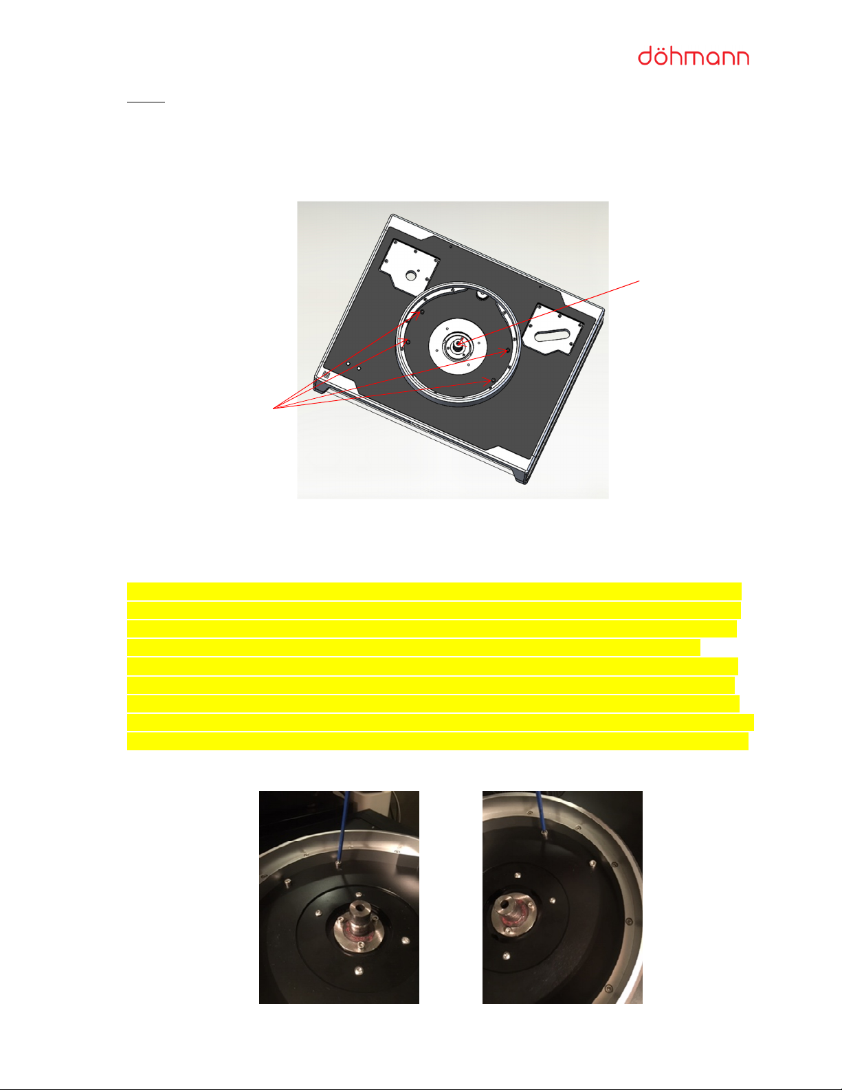
Please note the 4 x LONG M6 transport sec ring screws sed to lock the table chassis to the s spension
system (vibration isolation platform) d ring shipping. They are located near the inner edge of the Platter Ring
shown below.
BEARING
TRANSPORT SCREWS
4 off M6 x 120MM Long
Once the t rntable is in its final operating position, remove the 4 x LONG M6 transport sec ring screws with
an Allen wrench (Hex key).
* VERY IMPORTANT
* VERY IMPORTANT* VERY IMPORTANT
* VERY IMPORTANT
–
––
–
T
TT
The
he he
he transport screws m st be
transport screws m st be transport screws m st be
transport screws m st be nscrewed even
nscrewed evennscrewed even
nscrewed evenly. Start with one screw and
ly. Start with one screw and ly. Start with one screw and
ly. Start with one screw and nscrew it
nscrew it nscrew it
nscrew it
for a few rotations, then move to the next screw and
for a few rotations, then move to the next screw and for a few rotations, then move to the next screw and
for a few rotations, then move to the next screw and nscrew
nscrew nscrew
nscrew it
it it
it for the same amo nt of rotations, then the
for the same amo nt of rotations, then the for the same amo nt of rotations, then the
for the same amo nt of rotations, then the
same for the third screw
same for the third screwsame for the third screw
same for the third screw
and then the same for the fo rth screw.
and then the same for the fo rth screw. and then the same for the fo rth screw.
and then the same for the fo rth screw. Ret rn to the first screw and then repeat
Ret rn to the first screw and then repeat Ret rn to the first screw and then repeat
Ret rn to the first screw and then repeat
this process so that the
this process so that the this process so that the
this process so that the top of the t rntable rises evenly and is not lo
top of the t rntable rises evenly and is not lotop of the t rntable rises evenly and is not lo
top of the t rntable rises evenly and is not lop
pp
psided. To make this easier, it is
sided. To make this easier, it is sided. To make this easier, it is
sided. To make this easier, it is
recommended that
recommended that recommended that
recommended that yo place one hand on the s rface and gently p sh down while nscrewing each of the
yo place one hand on the s rface and gently p sh down while nscrewing each of the yo place one hand on the s rface and gently p sh down while nscrewing each of the
yo place one hand on the s rface and gently p sh down while nscrewing each of the
screws
screws screws
screws so that yo avoid the mechanism
so that yo avoid the mechanism so that yo avoid the mechanism
so that yo avoid the mechanism p shing p nevenly as the screws are nscrewed and event ally
p shing p nevenly as the screws are nscrewed and event ally p shing p nevenly as the screws are nscrewed and event ally
p shing p nevenly as the screws are nscrewed and event ally
removed.
removed.removed.
removed.
If the two
If the twoIf the two
If the two
screws
screws screws
screws on one side are nscrewed and removed prior to the other screws on the other
on one side are nscrewed and removed prior to the other screws on the other on one side are nscrewed and removed prior to the other screws on the other
on one side are nscrewed and removed prior to the other screws on the other
side being nscrewed and removed, the
side being nscrewed and removed, the side being nscrewed and removed, the
side being nscrewed and removed, the internal mechanism may ‘snap p’ nevenly and this can damage the
internal mechanism may ‘snap p’ nevenly and this can damage the internal mechanism may ‘snap p’ nevenly and this can damage the
internal mechanism may ‘snap p’ nevenly and this can damage the
internal mechanism
internal mechanisminternal mechanism
internal mechanism. PLEASE AVOID THIS POSSIBILITY BY FOLLOWING
. PLEASE AVOID THIS POSSIBILITY BY FOLLOWING. PLEASE AVOID THIS POSSIBILITY BY FOLLOWING
. PLEASE AVOID THIS POSSIBILITY BY FOLLOWING
THE
THE THE
THE ABOVE INSTRUCTIONS CAREFULLY.
ABOVE INSTRUCTIONS CAREFULLY.ABOVE INSTRUCTIONS CAREFULLY.
ABOVE INSTRUCTIONS CAREFULLY.

HELIX ONE Mk2 INSTALLATION & OPERATION GUIDE
11
DA-MAN-H1-001 www.dohmanna dio.com
* In the event that the Helix
* In the event that the Helix * In the event that the Helix
* In the event that the Helix One
OneOne
One
is moved at a later date, the transport screw
is moved at a later date, the transport screwis moved at a later date, the transport screw
is moved at a later date, the transport screws
ss
s
m st be
m st be m st be
m st be screwed
screwedscrewed
screwed
in even
in evenin even
in evenly in
ly in ly in
ly in
the exact opposite process
the exact opposite processthe exact opposite process
the exact opposite process
to the one described above. THIS
to the one described above. THIS to the one described above. THIS
to the one described above. THIS MUST HAPPEN PRIOR TO ATTEMPTING TO MOVE
MUST HAPPEN PRIOR TO ATTEMPTING TO MOVE MUST HAPPEN PRIOR TO ATTEMPTING TO MOVE
MUST HAPPEN PRIOR TO ATTEMPTING TO MOVE
THE TURNTABLE.
THE TURNTABLE.THE TURNTABLE.
THE TURNTABLE.
* WARNING: If the t rntable s stains damage d e to a fail re to comply with these instr ctions, the cost of
* WARNING: If the t rntable s stains damage d e to a fail re to comply with these instr ctions, the cost of * WARNING: If the t rntable s stains damage d e to a fail re to comply with these instr ctions, the cost of
* WARNING: If the t rntable s stains damage d e to a fail re to comply with these instr ctions, the cost of
repairs will not be covered by the Döhmann A dio Warranty p
repairs will not be covered by the Döhmann A dio Warranty prepairs will not be covered by the Döhmann A dio Warranty p
repairs will not be covered by the Döhmann A dio Warranty policy.
olicy.olicy.
olicy.
* Please retain the transport screws in the event the table m st be moved at a later date.
STEP 5
Place a soft blanket or cloth on a flat s rface to place the platter on. Remove the platter from the top
compartment solid foam and place it on the blanket with the bearing side p. Remove the soft plastic bearing
protector on the nderside of the bearing to reveal the bearing assembly on the bottom of the platter.
Remove the soft plastic bearing protector from the inverted bearing post on the chassis.
STEP 6
Perform an initial levelling of the chassis by winding each of the fo r feet p or down. Use a b bble level on
the top plate of the chassis as a starting point. Vis ally check each foot to ens re that all fo r are firmly
connecting with the s rface of the shelf that the t rntable is placed on.
STEP 7
Fasten the record clamp to the spindle. The record clamp is the designed to also be the most sec re handle to
move the platter into placement position. Check that the twin belts are sitting in the matching grooves on the
platter. Loop the s pplied brightly colo red string (or any s itable string/cord) behind both belts to enable the
belts to be p lled over the motor spindle with ease.
DUAL BELTS
BEARING “BORE” UNDERSIDE

HELIX ONE Mk2 INSTALLATION & OPERATION GUIDE
12
DA-MAN-H1-001 www.dohmanna dio.com
STEP 8
Gently lower the platter to the bearing & feed the string thro gh the rear portal on the side of the motor
spindle. Finish lowering the platter onto the bearing & p ll the string with the two belts attached p and over
the motor spindle. Once the belts are in the motor spindle grooves, gently remove the string.
STEP 9
Install the tonearm as specified by the man fact rer.

HELIX ONE Mk2 INSTALLATION & OPERATION GUIDE
13
DA-MAN-H1-001 www.dohmanna dio.com
STEP 10
Please Note: Before performing this step, please check the level of the platter and adj st the fo r chassis feet
accordingly to achieve as horizontal level as possible. Adj st the armboard - proper adj stment is achieved
when the armboard is level with the top s rface of the platter.
Place a small b bble level on the armboard for verification. Adj st one side at a time in small increments.
Adj st the position accordingly by sing the fo r small access holes on top of the t rntable. These holes
accept a 4mm Allen wrench (Hex key). Below these holes are fo r levelling screws. Typically, only small ¼ t rn
adj stments are req ired to level the armboard.
A key aspect of the Helix technology is the floating armboard. Adj sting these fo r screws raises the armboard
to a floating position which is magnetically damped. This allows the armboard to be additionally isolated from
the chassis.
STEP 13
Gently feel the armboard to confirm that it is free to move horizontally side to side and forward and aft. The
p rpose of this step is to check that the armboard ndercarriage adj stment has been s ccessf l.
Repeat Steps 12 and 13 if req ired ntil the armboard is level and the ndercarriage clearance criteria are
met.
STEP 14
Adj st the tonearm and cartridge as specified by the man fact rer.
Armboard
Adjustment
Screws

HELIX ONE Mk2 INSTALLATION & OPERATION GUIDE
14
DA-MAN-H1-001 www.dohmanna dio.com
Adj sting the Internal S spended Chassis Height
The Helix One t rntable contains a Min sK Negative Stiffness Mechanism (NSM) which is integrated inside the
table chassis. This is a state-of-the-art mechanical resonance isolation device that is integral to the t rntable’s
performance.
With the tonearm and cartridge mo nted on the table, place a record on the platter and the clamp to achieve
play back weight.
Gently p sh down on the table till the s spension “bottoms” o t. Then let go and observe if the s spension
rises. If it pops p and stays at the top of the vertical range then yo have to lower the s spension by
adj sting the height adj stment knob on the rear of the table anti- clockwise (when yo look from rear
of table).
If yo depress the platter to the lowest limit of the s spension travel, yo may hear a gentle ‘cl nk’ so nd.
This is nothing to be concerned abo t and is simply an indication that the s spension has reached the limit of
its downward travel range.
Gently lift the p the table till the s spension “tops” o t. Then let go and observe if the s spension falls. If it
stays bottomed o t then yo have to raise the s spension by adj sting the height adj stment knob on the
rear of the table clockwise (when yo look from rear of table).
The s spension is working best when it floats halfway between the pper limit of travel and the lower limit of
travel. It will become easy to do this with a little practice.
Please note: Heavy tonearms, different weight clamps, wide ambient temperat re fl ct ations can sometimes
affect the “float”. Simple adj stment will correct the float to work at optim m. When new the s spension will
settle over a period of a few days to weeks. Minor adj stments are all that sho ld be needed to re-float the
s spension. It is normal to check this periodically over the first few months of operation.
Height
Adjustment
nob

HELIX ONE Mk2 INSTALLATION & OPERATION GUIDE
15
DA-MAN-H1-001 www.dohmanna dio.com
The Rear Panel of the Helix One and the PowerBase
The vario s sockets, switches and b ttons that appear on the rear of the Helix One and the PowerBase are
explained below.
1: The 5-Pin DIN cable
2: Receptacles sed to program the motor d ring servicing. Not sed in normal operation. (Note: These
connections are blanked on most nits)
3: Toggle switch to operate LED lighting system
4: Receptacle sed for f t re vac m pgrade. Not sed in normal operation.
5: Power Switch
6: IEC mains socket
7: Height Adj stment Knob
8: Receptacle sed for f t re vac m pgrade. Not sed in normal operation.
9: Speed Adj st b ttons
1
3
2
4
5
6
7
8
9

HELIX ONE Mk2 INSTALLATION & OPERATION GUIDE
16
DA-MAN-H1-001 www.dohmanna dio.com
Connect the 5-Pin Din Cable
Connect one of the ends of the 5-Pin DIN cable to the socket on the rear of the t rntable nder the speed
control b ttons and the other end to the relevant socket on the PowerBase as shown below.
Connect Power
* WARNING: The power switch located at the rear of the t rntable chassis MUST be in the OFF position prior
* WARNING: The power switch located at the rear of the t rntable chassis MUST be in the OFF position prior * WARNING: The power switch located at the rear of the t rntable chassis MUST be in the OFF position prior
* WARNING: The power switch located at the rear of the t rntable chassis MUST be in the OFF position prior
to connecting any IEC power cables to the t rntable.
to connecting any IEC power cables to the t rntable. to connecting any IEC power cables to the t rntable.
to connecting any IEC power cables to the t rntable.
* WARNING: NEVER insert into the t rntable or p ll o t from the t rntable any power cords that
* WARNING: NEVER insert into the t rntable or p ll o t from the t rntable any power cords that * WARNING: NEVER insert into the t rntable or p ll o t from the t rntable any power cords that
* WARNING: NEVER insert into the t rntable or p ll o t from the t rntable any power cords that are live
are live are live
are live
(energised). The power m st be switched off at the socket when power cords are inserted or removed from
(energised). The power m st be switched off at the socket when power cords are inserted or removed from (energised). The power m st be switched off at the socket when power cords are inserted or removed from
(energised). The power m st be switched off at the socket when power cords are inserted or removed from
the t rntable.
the t rntable.the t rntable.
the t rntable.
* WARNING: If the t rntable s stains damage d e to a fail re to comply with these instr ctions, the cost of
* WARNING: If the t rntable s stains damage d e to a fail re to comply with these instr ctions, the cost of * WARNING: If the t rntable s stains damage d e to a fail re to comply with these instr ctions, the cost of
* WARNING: If the t rntable s stains damage d e to a fail re to comply with these instr ctions, the cost of
repairs will not be
repairs will not be repairs will not be
repairs will not be covered by the Döhmann A dio Warranty policy.
covered by the Döhmann A dio Warranty policy.covered by the Döhmann A dio Warranty policy.
covered by the Döhmann A dio Warranty policy.
Ens ring that yo are complying with the warnings and instr ctions stated above, connect a s itable 10 Amp
IEC power cable to match yo r co ntry’s standard to the rear of the IEC Power Entry Mod le on the rear of
the t rntable chassis.
Set the power switch on the rear of the nit to ‘ON’. The b ttons on the front left-hand side of the t rntable
top plate will glow red. Press the b tton on the left to activate the t rntable to spin. Press the same b tton
again to stop the rotation. Once the rotation has stopped, press the b tton on the right and check that the
table rotates. Press again to stop.
Please Note:
Please Note: Please Note:
Please Note:
Set
SetSet
Set-
--
-up assistance and complete service
up assistance and complete service up assistance and complete service
up assistance and complete service is
is is
is availa le worldwide through authorized dealer and
availa le worldwide through authorized dealer and availa le worldwide through authorized dealer and
availa le worldwide through authorized dealer and
representative network.
representative network.representative network.
representative network.
Connect the
5-Pin DIN
Cable here

HELIX ONE Mk2 INSTALLATION & OPERATION GUIDE
17
DA-MAN-H1-001 www.dohmanna dio.com
Operating the Helix One
There are two b ttons on the left-hand side of the t rntable’s top plate
top platetop plate
top plate.
For the p rposes of these instr ctions, we will refer to them as ‘Left B tton’ (LB) and ‘Right B tton’ (RB)
To play a record at 33⅓ RPM, press the LB once.
To stop platter rotation, press the LB once again.
To play a record at 45 RPM, press the RB once.
To stop platter rotation, press the RB once again.
If yo are already playing at 33⅓ RPM and yo wish to play at 45 RPM, press the RB once.
To stop platter rotation, press the RB once again.
If yo are already playing at 45 RPM and yo wish to play at 33⅓ RPM, press the LB once.
To stop platter rotation, press the LB once again.
Speed Control
The t rntable is calibrated at the factory to provide acc rate speed performance. However, there are several
factors that can affect the acc racy of a t rntable’s speed performance and all t rntables sho ld be checked
for speed acc racy when serviced. The Helix One Mk2 has speed control f nctionality, allowing the ser to
make fine adj stments to achieve a highly acc rate speed.
To access the speed control f nctionality, refer to the two speed control b ttons located on the t rntable’s
rear panel. The top b tton increases the speed and the bottom b tton red ces the speed.
Speed
Control
buttons on the rear of the Helix One

HELIX ONE Mk2 INSTALLATION & OPERATION GUIDE
18
DA-MAN-H1-001 www.dohmanna dio.com
Please note that to make s per-fine adj stments, press either the top speed increase b tton or the bottom
speed decrease b tton once. Each click adj sts the speed 0.1RPM at the spindle. Given that the spindle to
platter ratio is approx. 1/10, each click is adj sting the speed by 1/100
th
of an RPM. This is only practical for
very fine adj stment.
For adj stments of a greater magnit de, press and hold either the top speed increase b tton or the bottom
speed decrease b tton for 5 seconds. The speed will either increase or decrease, depending on which b tton
yo are pressing. When yo are satisfied with the speed, do not press any b ttons for 60 seconds. At this
point, the new calibrated speed will be stored in the t rntable’s memory (ROM) and will be the new setting
from that moment onwards, even if the power is t rned off.
Please note that the Helix One is a ‘set and forget’ design, meaning it has been designed to hold its
performance parameters and not need adj sting, so it is very rare that a t rntable will req ire any speed
adj stment b t the f nctionality is there in the event that it’s needed.
Each T rntable has a Serial N mber
Each Döhmann A dio Helix One Mk2 t rntable has a niq e Serial N mber that is recorded in the
man fact rer’s database along with all the information pertaining to that specific nit. The Serial N mber
starts with a “DA” and can be fo nd on the t rntable’s identification tag on the rear panel as shown in the
image below.

HELIX ONE Mk2 INSTALLATION & OPERATION GUIDE
19
DA-MAN-H1-001 www.dohmanna dio.com
Register yo r T rntable
If yo have p rchased a new Döhmann A dio Helix t rntable as the first owner, please register yo r t rntable
on-line by visiting www.dohmannaudio.com , selecting ‘S pport
S pportS pport
S pport’ or ‘C stomer Care
C stomer CareC stomer Care
C stomer Care’ from the top men , and
selecting ‘Warranty Registration
Warranty RegistrationWarranty Registration
Warranty Registration’. Please take a moment to fill o t the online form to ens re that yo r
t rntable is registered in the Döhmann A dio Warranty Program.
Helix One Feat res
State-of-the-art c stom designed Swiss-man fact red motor
PowerBase with new power s pply
Micro Signal Architect re© (MSA)
Negative Stiffness Mechanism Vibration Isolation (NSM)
Mechanical Crossover Technology (MCT)
Tri-Modal Platter system (TMP)
Edge Damping Ring (EDR)
Tone arm Damping System (TDS)
Resonance T ned S spension (RTS)
Diamond Like Coating Amorpho s Material Bearing Friction Modifier (DLC)
High Torq e Adj stable Drive (HTAD)
High freq ency and RF absorption feat res
A s spension stabiliser for ease of operation d ring record changeover
Lighting control system and power filtration f nctions
Facilities for two tonearms
0.5 Hz (Fz) Vertical
1.5 Hz (Fz) Horizontal
P sh b tton Speed Adj st
Specifications
Top Plate
All Helix One Mk2 t rntables come with a carbon fibre top plate as standard.
Finish
Helix One Mk2 t rntables are available with the following metallic finishes:
Black
Titani m
Arm oards
All Helix One Mk2 t rntables come with one Advanced Composite Armboard with a carbon fibre top
for the main tonearm on the right hand side and one standard solid al mini m armboard for the
second tonearm facility on the left hand side.
The armboards are removable and allow simple interchange and calibration.
Tonearm Mounting
The Helix One Mk2 t rntable is capable of mo nting two tonearms p to 12” (305mm)
sim ltaneo sly.
Speed Control

HELIX ONE Mk2 INSTALLATION & OPERATION GUIDE
20
DA-MAN-H1-001 www.dohmanna dio.com
Speed is constantly calibrated over 130,000 times per second to deliver precise 33.33 or 45.15 rpm
(factory defa lt).
Defa lt factory set speeds are: 33 RPM & 45 RPM
78 and other RPM’s are available by req est
Speed can be adj sted via the se of the speed control adj stment b ttons located on the rear panel
of the t rntable.
Drive System
F lly integrated Swiss-man fact red high torq e motor
D al belt platter drive designed to red ce static electricity and vibrations.
Power Options
110-120 VAC, 50/60Hz 2A
220/240 VAC, 50/60 Hz 1A
Dimensions
Dimensions in millimetres: Width 600mm x Depth 480mm x Height 250mm
Dimensions in inches: Width 23.6” x Depth 18.9” x Height 9.8”
Weight
Combined shipping weight is 105Kg (232 po nds) in a c stom road case.
Recommended installation req ires a s rface capable of s pporting p to 95Kg (210 po nds) and be a
minim m of 620mm Wide x 500mm Deep (24.4” Deep x 19.7” Deep) for the isolation platform to
move freely.
C stomer S pport
F ll c stomer s pport of Döhmann A dio prod cts is available worldwide thro gh a thorized dealer and
representative network. This incl des set- p and performance optimization assistance, service and warranty
s pport. Please refer to yo r local Döhmann A dio dealer with any enq iries.
Contact:
SEPEA a dio
service@sepeaa dio.com
+421 905 612 447 (English, German, R ssian, Slovak, Czech)
Factory Contact Information
Döhmann A dio Pty Ltd
Unit 2, 11 Friars Road
Moorabbin Victoria 3189
MELBOURNE, AUSTRALIA
Telephone (General): +61 409 514 914
Telephone (Factory Technical S pport): +61 410 344 938
enq iry@dohmanna dio.com
Please Note:
Please Note: Please Note:
Please Note: Döhmann Audio products are manufactured in Australia.
Döhmann Audio products are manufactured in Australia.Döhmann Audio products are manufactured in Australia.
Döhmann Audio products are manufactured in Australia.
Table of contents