Dacia Solenza 2004 Operating instructions

REPAIR MANUAL
DACIA
MR 525-1 MECHANICS
ENGINE: E7J
GEARBOX: JH3
TAPV: B41A, B41B, B41C
Ref: 6001999066 MARCH 2004 English version
The reparation methods prescribed by the manufacturer in the present document are established subject to
technical specifications in force at the document issuing date.
These are subject to modifications brought by the manufacturer at the fabrication of different assemblies,
subassemblies or accessories of its vehicles.
All rights reserved to SC Automobile Dacia SA.
Reproduction or translating even partially of this present document is forbidden without the written
authorisation of AUTOMOBILE DACIA S.A.
vnx.su

CHARACTERISTICS
Engine – Clutch - Gearbox .................................. 01-1
Vehicle identification .......................................... 01-2
LIFTING MEANS
Mobile jack – Adjustable supports ..................... 02-1
Elevator positioned under vehicle body .............. 02-2
TOWING
All types .............................................................. 03-1
LUBRICANTS – INGREDIENTS
Condition ............................................................ 04-1
DRAINING – FILLING
Engine.................................................................. 05-1
Gearbox .............................................................. 05-2
Power steering ..................................................... 05-3
VALUES AND ADJUSTMENTS
Dimensions.......................................................... 07-1
Weights (kg) ........................................................ 07-2
Capacity - Quality................................................ 07-3
Accessories belts tension ..................................... 07-4
Wheels, Tires....................................................... 07-5
Brakes.................................................................. 07-6
Dimensions under carriage body ......................... 07-7
Checking values of the front axle angles.............. 07-8
Checking values of the rear axle angles .............. 07-9
ENGINE ASSEMBLY
Ingredients............................................................ 10-1
Oil consumption ................................................. 10-2
Oil pressure ......................................................... 10-3
Power train group................................................. 10-4
Separation - Gearbox .......................................... 10-9
Separation – Unfitting ......................................... 10-10
Tightening moments ........................................... 10-11
Special tools......................................................... 10-12
Characteristics ..................................................... 10-13
Dismounting –Remounting................................. 10-20
Lower casing ...................................................... 10-39
Oil pump.............................................................. 10-41
Multi-purpose support ......................................... 10-42
DISTRIBUTION SYSTEM
Distribution belt ........................................................ 11-1
Cylinder head gasket ............................................... 11-3
FUEL MIXTURE
Characteristics .......................................................... 12-1
Body valve ................................................................. 12-4
Inlet manifold ........................................................... 12-5
Exhaust manifold ...................................................... 12-6
Air filter .................................................................... 12-7
FUEL SUPPLY
Supply interruption .................................................. 13-1
Fuel ramp .................................................................. 13-2
Pump capacity ........................................................... 13-3
Supply pressure ......................................................... 13-4
ANTI-POLLUTION
Petrol vapors re-aspiration ...................................... 14-1
Oil vapors re-aspiration ............................................ 14-4
ALTERNATOR – STARTER
Alternator ................................................................. 16-1
Starter ........................................................................ 16-6
IGNITION AND INJECTION
Ignition system ......................................................... 17-1
Spark plags ............................................................... 17-3
Injection system ....................................................... 17-4
Characteristics .......................................................... 17-10
Injection / air conditioning strategy ......................... 17-11
Idling regime correction ........................................... 17-12
Idling regime adaptive correction ............................ 17-13
Enriching adjustment ............................................... 17-14
Enriching adaptive correction .................................. 17-16
“On Board Diagnostic” system characteristics ....... 17-18
“On Board Diagnostic” lighting conditions ............. 17-19
“On Board Diagnostic” diagnostic conditions ......... 17-20
Diagnostic of combustion misfires detection ............ 17-21
Catalyst diagnostic .................................................... 17-22
Oxygen sensor diagnostic ......................................... 17-23
Diagnostic – General ................................................. 17-25
Diagnostic – Failures interpretation ......................... 17-26
Diagnostic – Help ...................................................... 17-60
Diagnostic – Conformity checking ............................ 17-61
Diagnostic – States interpretation ............................ 17-69
Diagnostic – Parameters interpretation .................. 17-75
Failure locating algorithm ........................................ 17-83
COOLING - EXHAUST - TANK
Characteristics .......................................................... 19-1
Filling - Purging ........................................................ 19-2
Checking ................................................................... 19-3
Cooling system diagram ........................................... 19-4
Radiator ..................................................................... 19-5
Cooling engine fan for vehicles
without air conditioning ............................................ 19-7
Diagnostic – failures interpretation at vehicles
without air conditioning ............................................. 19-8
Cooling engine fan for vehicles
General poinds vehicle0
01
02
03
04
05
07
Engine and péripheriques
1
10
11
12
13
14
16
17
19
vnx.su

with air conditioning ................................................... 19-9
Diagnostic – failures interpretation
at vehicles with air conditioning ............................... 19-10
Water pump ............................................................... 19-11
Exhaust Assembly...................................................... 19-13
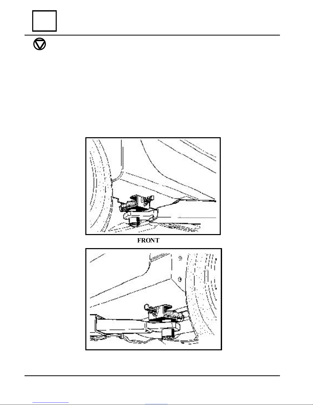
Fuel tank .................................................................... 19-15
Fuel pump ................................................................. 19-22
Fuel filter ................................................................... 19-24
Engine suspension ..................................................... 19-25
CLUTCH
Identification ............................................................. 20-1
Diagnostic .................................................................. 20-2
Clutch disk – Mechanism ......................................... 20-5
Pressure bearing – Clutch releasing fork ................ 20-7
Engine flywheel ................................................. 20-8
MECHANICAL GEARBOX
Sectional view .................................................... 21-1
Identification ...................................................... 21-2
Tightening moments in daNm .......................... 21-3
Particurarities .................................................... 21-4
Ratios .................................................................. 21-5
Ingredients .......................................................... 21-6
Capacity, lubricants .......................................... 21-7
Parts that are replaced after
each dismonting ................................................. 21-8
Necessary special tools ...................................... 21-9
Gearbox dismounting ........................................ 21-10
Replacement of the planetary sealing
gasket (on the vehicle) ....................................... 21-30
Replacement of the 5-th gear synchroniser
and pinion (on the vehicle) .................................. 21-32
TRANSMISSION
Front transversal transmission ........................ 29-1
Bellows - Bearing assembly to
the gearbox (left) ............................................... 29-4
Bellows to wheel (left) ....................................... 29-7
Bellows to gearbox (right) ................................. 29-12
Bellows to wheel (right) .................................... 29-15
GENERAL
General principle schedule
of the brake circuit ............................................ 30-1
Tightening moments (in daNm) ....................... 30-2
Composition and dimensions
of the main braking system elements ............... 30-6
Braking system diagnostic ................................ 30-7
Brake connections and ducts ............................ 30-12
Brake fluid ......................................................... 30-13
Braking system purging .................................... 30-14
The influence of angles ...................................... 30-16
Angles checking principle ................................. 30-17
Front axles checking and adjustment ............. 30-18
FRONT AXLESELEMENTS
Characteristics ..................................................... 31-1
Suspension arm ................................................. 31-2
Elastic bushings of the suspension arm ........... 31-5
Suspension ball joint .......................................... 31-6
Brake lining (pads) ............................................ 31-7
Checking the brake pads wear ......................... 31-9
Brake caliper ...................................................... 31-10
Brake disk ........................................................... 31-12
Steering knuckle ................................................. 31-13
Steering knuckle bearing (35 x 65 x 35) ......... 31-15
Front suspension ................................................ 31-16
Shock absorber, Spring ...................................... 31-17
Spring – shock absorber assembly ................... 31-18
Anti roll bar ........................................................ 31-20
Power train support .......................................... 31-21
REAR AXLES ELEMENTS
Characteristics ................................................... 33-1
Rear axle ............................................................. 33-2
Rear suspension ................................................. 33-4
Shock absorber ................................................... 33-5
Spring ................................................................. 33-6
Brake drum ........................................................ 33-7
Brake cylinder .................................................... 33-8
Brake shoes ......................................................... 33-10
Bearing ................................................................ 33-13
WHEELS AND TIRES
Characteristics ................................................... 35-1
Wheels balancing ............................................... 35-4
STEERING ASSEMBLY
Steering connecting rods .................................. 36-1
Manual steering box .......................................... 36-3
Steering box pusher ........................................... 36-4
Noise absorbant bushing .................................. 36-5
Bellows................................................................ 36-6
General .............................................................. 36-7
Power steering box ............................................ 36-8
Power steering box pusher ............................... 36-11
Power steering pump ......................................... 36-12
Steering column ................................................. 36-14
THE MECHANICAL ELEMENTS CONTROLS
Brake pump........................................................ 37-1
Servobrake ......................................................... 37-3
Air filter – servobrake retainer valve .............. 37-6
Handbrake - adjustment ................................... 37-7
Handbrake control lever ................................... 37-8
Handbrake secondary cables ............................ 37-10
Brake flexible hoses ........................................... 37-11
Brake pressure controller .................................. 37-13
Gears control ..................................................... 37-15
Clutch and brake pedals ................................... 37-17
Clutch cable ........................................................ 37-18
Pedals support ................................................... 37-20
Acceleration control .......................................... 37-21
20
21
29
30
31
33
35
36
37
Transmission
2
Chasis
3
vnx.su

01 - 1
CHARACTERISTICS
Engine – Clutch - Gearbox 01
VEHICLETYPE
ENGINE
TYPE CYLINDER
CAPACITY
(cm
3
)
CLUTCH
TYPE
GEARBOX
TYPE
DACIA SOLENZA E7J-262 1390 180 CPO 3300 JH3 - 051
vnx.su

01 - 2
01 CHARACTERISTICS
Vehicle identification
MANUFACTURERPLATE
Themanufacturerplateis located on the radiator front
crossbeam.
1. Homologation number
2. Modelyearcodeand carriagebody manufacturerseries.
3. Maximumtechnicaladmissibleweight of theloadedcar
4. Totalmaximumadmissibleweight(oftheassembly)
5. Maximumtechnicaladmissibleweighton frontaxle;
6. Maximumtechnicaladmissibleweightonrearaxle.
7. Vehiclecode
8. Trailermaximum authorizedweight without braking system
....... Kg
....... Kg
....... Kg
....... Kg
1
3
87
2
6
5
4
Manufacturer plate
VIN identification number
UNITLTHEDATEOF 26.06.2003
vnx.su

01 - 3
01
CHARACTERISTICS
Vehicle identification
VINIDENTIFICATIONNUMBER
5 A 7 1 5 3 * * * * * * *
POSITION CHARACTERS EXPLANATION
1 - 3 – manufacturer world identification,
UU1– AUTOMOBILEDACIASA.ROMANIA,
4– vehicle destination,
R– vehiclefor personstransportation,
5– powertrainunitlocation,
5– transversal front engineandfront drive,
6–carriagebody type,
A– Hatchback(two volumessedan)– restyledI,
7– payloadlocation,
7– 5 places: 2 front places + 3 rear fix bench places,
8– gearbox type,
1– gearbox with 5 + 1 steps,
9– enginecodeand vehicledriving postlocation,
5– spark ignitionengine (cylindercapacity1400cm3),
E7J 262 EURO2, left handdrive,
6– spark ignitionengine (cylindercapacity1400cm3),
E7J 262 EURO3, left handdrive,
10 – year model code -3- 2003,
11 - 17 – carriagebodymanufacturingnumber.
Positionn 1 2 3 4 5 6 7 8 9 10 11 12 13 14 15 16 17
Code U U 1 R
VINIDENTIFICATIONNUMBER
UNITLTHEDATEOF 26.06.2003
vnx.su

01 - 4
Fig.2.1
01 CHARACTERISTICS
Vehicle identification
MANUFACTURER’SPLATEDISPOSALTYPESELF-ADHESIVE
STARTINGWITH THE DATEOF26.06.2003
vnx.su

01 - 5
APVIDENTIFICATIONDATA
1.1Code type auto APV
1.2Manufacturingnumber
2.1 Equipping levelcode
2.2 Additional code for limited serial
definition
2.3 Additional code for specialserial
definition
3.1 Carriagebody color code
3.2 Seats upholstery code
3.3 Interiormatching code.
4.1 Technicaldefinition code
4.2 Optionalequipping code.
A
C
D
F
B
H
G
I
J
E
MANUFACTURER’S
IDENTIFICATIONDATA
A. Manufacturer’sname
B. Community reception number or
homologation number.
C.Identificationnumber.
D. Total authorized weight of the
loaded vehicle.
E. Total authorizedrunningweight
F. Totalweight on front axle.
G. Total weight on rear axle.
H. Additionalinscription.
I.Manufacturing date inscription
J. Consignmentnumber.
The MANUFACTURER PLATE, self-adhesive type, has the bellow presented con-
figuration,withtwodistinctiveareas,presenting :manufacturer’sidentificationdata and
APV typeidentification data.
01
CHARACTERISTICS
STARTINGWITH THE DATEOF26.06.2003
Vehicle identification
vnx.su

02 - 1
02
LIFTING MEANS
Safety sign (particularlycautionsto be observed in case of an intervention)
SPE CIA L TOOLS
Cha 280-02 Adequatesupporton mobile jack
Cha408-01 Adjusting supporton mobile jack
Cha408-02 Adjusting supporton mobile jack
Mobile jack – Adjustable supports
The use of a mobile jack implies the
obligatoryuse of adjustable supports.
Itisforbidden the vehicle lifting using
othersupporting points (suspensionarms, etc)
than the onesprovided bymanufacturer.
LATERALMOBILE JACK
In order to lift vehicle front or rear part,
the same supporting points provided for the
vehicle jack are to be used.
This type of jack, is using sockets
(supports) Cha 408-01 or Cha 408-02,
equipped with the supportCha280-02.
Place iton underthe thresholdatthe front
doorlevel and the floor closing plate shall be
positioned in the channel ofthe support.
ADJU STABLESUPPORT S
The adjustable su pports, maybe placedunder
the carriage body, in two ways:
-underthe reinforcementsprovided for the
lifting vehicle withthe vehicle jack;
-under the supports placed behind the
reinforcements.
The positioning of the adjustable supports in
the vehicle rear areasisperformed by lateral lift-
ing of the vehicle, bymeansof a mobile jack.
vnx.su

02 - 2
LIFTING MEANS
FRONT
02 Elevator positioned under vehicle body
SAFE TY SIGN
Situationsto be considered:
1. SITUATION OF VEHI CLE COMPONE NTSDISMOUNTING
When there are notavailable four columnselevators, two columnselevatorsmay be used, in
thiscase, lifting slidesshall be placed under the floor closing plate, atthe supporting points level
of the vehicle jack
2. PARTI CULARLY SITUATION OF POWER-TRAIN DISMOUNTING – RE-
MOUNTING
In this specific case, the vehicle carriage bodyshall be consolidated with the two columns
elevator armsusing special slides.
REAR
These mustbeobligatoryplaced atthe rightof the supporting pointsof the vehicle jack and
must be locked in the holes/windowsmade in the floor closing plate.
vnx.su

03 - 1
03
TOWING
ATTEN TIO N !
NEVER USE AS TOWING POINTS, THE TRANSMISSION AXLES (PLAN-
ETARY SHAFTS).
Thetowingpoints,front, or rear,areto beusedonly for vehiclestowingon wheels.
These points cannot beanyhow usedfor drawingout the damaged vehicle froma trench
(hole),or for directorindirectvehicleliftingon atransport platform.
FRONT (right) REAR (left)
All types
vnx.su

04 - 1
PRODUCT PLACE WHEREIT IS USED
OILING(GREASING)
Grease
OLISTA LONG TIME 3EP R100137188
Grease
ELFCARDREXARNT2
Grease
MOLYKOTE33M
Grease
UM 185 Li2M
Guidingtube,clutchreleasefork
Right transmissionjointG.I
Transmissionjoint G.E.
Gearbox controlrod protectionbellows
Attachmentbufferonanti-rollbar
Steering rack,pinion, oilsealring(steering
box)
LUBRICANTS – INGREDIENTS 04
Condition
vnx.su

04 - 2
LUBRICANTS – INGREDIENTS
PRODUCT PLACE WHEREIT IS USED
ETANªARE
LOCTITE 518
LOCTITE 5900
(RHODORSEAL 5661)
Sealing paste Wurth
Waterpump
Thermostatsupport
Crankshaft halfcrankcase
Gearbox crankcasesassembling
Threadof thereversedrivingcontact
Crankshaft no.1bearing cap
Enginelowercrankcase
Exhaust
SOLDERING
LOCTITE 270
(FRENBLOC)
LOCTITE243
(FRENETANCH)
Screwof secondary shaft
Crankshaftflywheelscrew
Enginebalancewheelscrew
CLEANING
LOCTITE
METALLREINIGER
(DECAPJOINT)
Aluminumpartssurfaces
04 Condition
vnx.su

05 - 1
DRAINING – FILLING
Draining :plug(2)Filling:plug(1)
SPECIAL TOOLS - wrench MOT 1018
05
Engine
21
vnx.su

05 - 2
DRAINING – FILLING
Drain:plug(2)Fill:plug(1)
05 Gearbox
Special tools - wrench MOT 1018
2
1
vnx.su

05 - 3
DRAINING – FILLING 05
Power steering
ATTEN TION !
For filling and addition, only oil DACIA of class DEXTRON II D is to be used.
Circuit capacity: 1 liter.
CIRCUITFILLING
Fillthereservoirwithoil.
In ordertofillthe circuit withoil, easy rotatethesteering wheelin both directions so that
steering rackisperforminga completestroke.
Checktheoillevelinthereservoirandadditionifthecase.
Start the engine, easy rotate the steering wheel in bothdirections so that steeringrack is
performinga completestroke.
Restore theoillevelinthe reservoirtillMAXI level.
LEVELCHECKING
Each10,000km, checktheoillevelin thereservoir,thatmustbebetweentheMINI-MAXI
marks.
vnx.su

VA L UES AND ADJUSTMENTS 07
07 - 1
Dimensions
Dimensions(mm)
Total length: 4083
Totalwidth: G = 1664
Totalheight:
* empty H = 1379
* loaded(authorizedmaximumtotalweight) 1329
Wheelbase * empty A = 2476
* loaded 2479
Front wheeltrackwidth,ground levelmeasurement:
* empty E = 1429
* loaded 1428
Rearwheeltrackwidth,ground levelmeasurement F = 1348
Ground clearance (K)
* empty -
* loaded 120
vnx.su

VA L UES AND ADJUSTMENTS
07
07 - 2
Optional equipment weight disposal on shafts axles
Front axle Rear axle
Airconditioning 23 0
Powersteering 17 0
Weights (kg)
Version
Vehicletype
Unloadedvehicleweight
Maximumauthorizedweight
on axle
Maximum technical
admissibleweightof the
loadedvehicle
Maximum technical admissible towing
weight(trailerwithout braking system)
Maximumtechnicaladmissibletowing
Weight(trailerwithbraking system)
Maximumadmissibleweight of the
assembly
Maximumloadon towinghook
Towinghookweight
1,4
R5A715
1035
592
443
1075
632
443 730
800
1450
718
732
450
800
2250 2260
40
20
R5A716
1045
602
443
1085
642
443
1460
728
732
Minim
Front
Rear
Maxim
Front
Rear
Front
Rear
Total
Front
Rear
vnx.su

VA L UES AND ADJUSTMENTS 07
07 - 3
Capacity - Quality
DENOMINATION QUALITY CAPACITY (l)
(approximate )*
Engine oil DACIA OIL EXTRA SAE 10 W 40; API SJ 2,9*
Gearbox oil SAE 75 W 80 W; API GL 5 3,5
DACIAOIL EXTRAGEAR
Breaking fluid SAE J 1703 DOT 4 0,450
Cooling fluid 50% antigel GLACEOL RXtypeD
50% distilledwater 6
RefrigerantAC HFC – 134 a 0,600 kg
Compressoroil PA G SP 10 or SP 20 135 cm3
* tobe adjustedat dipstick
vnx.su

VA L UES AND ADJUSTMENTS
07
07 - 4
Accessories belts tension
Beltstensioningvaluesare:
- alternator belt 253 – 273 Hz
- compressor belt 150 – 155 Hz
- powersteering pumps belt 151 – 161 Hz
- compressor belt/ DA pump 222 ± 8 Hz
Accessoriesbelt tensioning method.
Belttensioningisto be performedwithcoldengine.
Mountthenewbelt.
Tightenthe belttillobtainingtheprescribed mounting tensioning.
Blockthetensioner.
Perform threeenginecrankshaftrotations.
Placethereading headof the MOT 1505 devicein themeasurement area andcheck ifthe
belttensioningiswithinthemountingprescribedvalues;restore isnecessary.
REMARK :
Once a belt is dismounted, is not to be remounted, but replaced.
A –crankshaft C– Compressor T– Tensioner pulley.
B –alternator D– Power steering pump – Tensioning checking point.
B
A
A
D
T
A
C
T
T
vnx.su
Table of contents
Other Dacia Automobile manuals