Daewoo AKD-80C User manual

Service Manual
Car Audio
COMPACT DISC CHANGER
MODEL:AKD-80C
DAEWOO ELECTRONICS CO., LTD

DAEWOO
CONTENTS
- 1 -
GENERAL SPECIFICATIONS......................................................2
GENERAL....................................................................................3
DISASSEMBLY............................................................................7
DIAGRAMS...................................................................................................10
PARTS LIST.................................................................................................26
1.IDENTIFICATION OF PARTS...........................................................................3
2.INSTALLATION PARTS AND SUPPLIED MOUNTING HARDWARE...........3~4
3.INSTALLATION METHOD (HOW TO INSTALL THE UNIT)...............................5
4.INSTALLATION METHOD (HOW TO INSTALL THE VEHICLE)........................6
5.PREPARATIONS............................................................................................6
1.DISASSEMBLY..............................................................................................7
2.PICK-UP/MECHANISM/MAGAZINE ASSEMBLY...............................................8
3.IDENTIFICATION OF MAGAZINE.....................................................................9
1.SCHEMATIC DIAGRAM.................................................................................10
2.ELECTRICAL SPECIFICATION........................................................................11
3.MICOM PIN CONFIGURATION & DESCRIPTIONS.................................12~14
4.IC BLOCK DIAGRAM & TERMINAL VOLTAGE........................................15~23
5.PRINTED CIRCUIT BOARDS...................................................................24~25
ELECTRICAL PARTS LIST.....................................................................26~27

GENERAL SPECIFICATIONS
DAEWOO
Compact Disc Digital Audio System
Material : GAAIAS
Wavelength : 780nm
Emission Duration : Continuous
Laser Output Power : Less Than 44.6uW
5-20,000Hz + 1dB
Below Measurable Limit
90dB
Line Output (For changer Connector Only)
800mA (CD Play Back)
800mA (During Loading or Ejection a Disc)
-10
o
C to 55
o
C (14
o
F to 131
o
F)
Appro x 245 x 85 x174mm (W x H x D)
Not lncl. Projection Parts and Control
Approx. 2.3kg
12V DC Car Battery
(Negative Ground)
Disc Magazine (1)
Mounting Hardware(1Set)
Connecting Cable (1)
System
Laser Diode Properties
Frequency Response
Wow and Flutter
Signal-To Noise Ratio
Outputs
Current Drain
Operating Temperature
Dimensions
Weight
Power Requirement
Supplied Accessories
- 2 -
NOTES ON HANDLING THE OPTICAL PICK-UP BLOCK OR BASE UNIT
1. The laser diode in the optical pick-up block may suffer electrostatic breakdown because of the
potential difference generated by the charged electrostatic load, etc. on clothing and the human
body.
2. During repair, pay attention to electrostatic breakdown and also use the procedure in the printed
matter which is included in the repair parts.
3. The flexible board is easily damaged and should be handled with care.
CAUTION :
USE OF CONTROLS, ADJUSTMENTS, OR PERFORMANCE OF PROCEDURES OTHER THAN THOSE SPECIFIED
HEREIN, MAY RESULT IN HAZARDOUS RADIATION EXPOSURE.
THE COMPACT DISC PLAYER SHOULD NOT BE ADJUSTED OR REPAIRED BY ANYONE EXCEPT PROPERLY
QUALIFIED SERVICE PERSONNEL.
GENERAL
DAEWOO
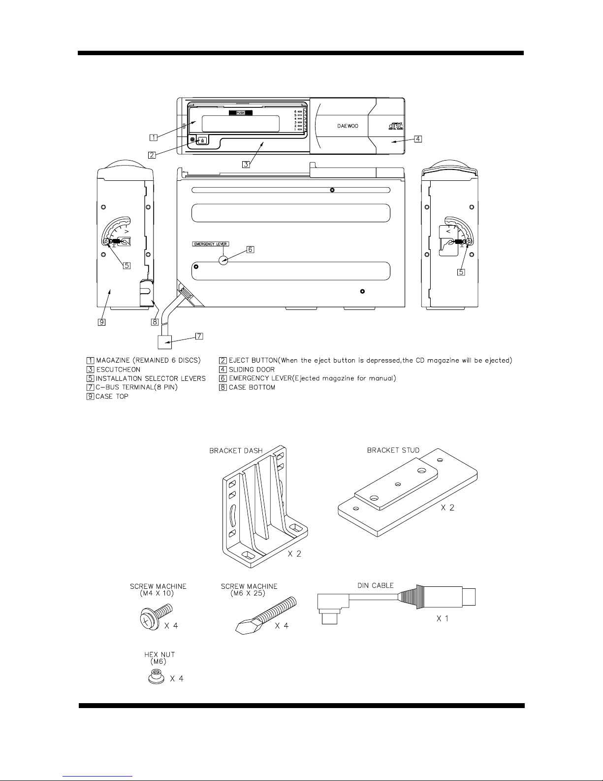
1.IDENTIFICATION OF PARTS
2. INSTALLATION PARTS AND SUPPLIED MOUNTING HARDWARE
- 3 -
DAEWOO
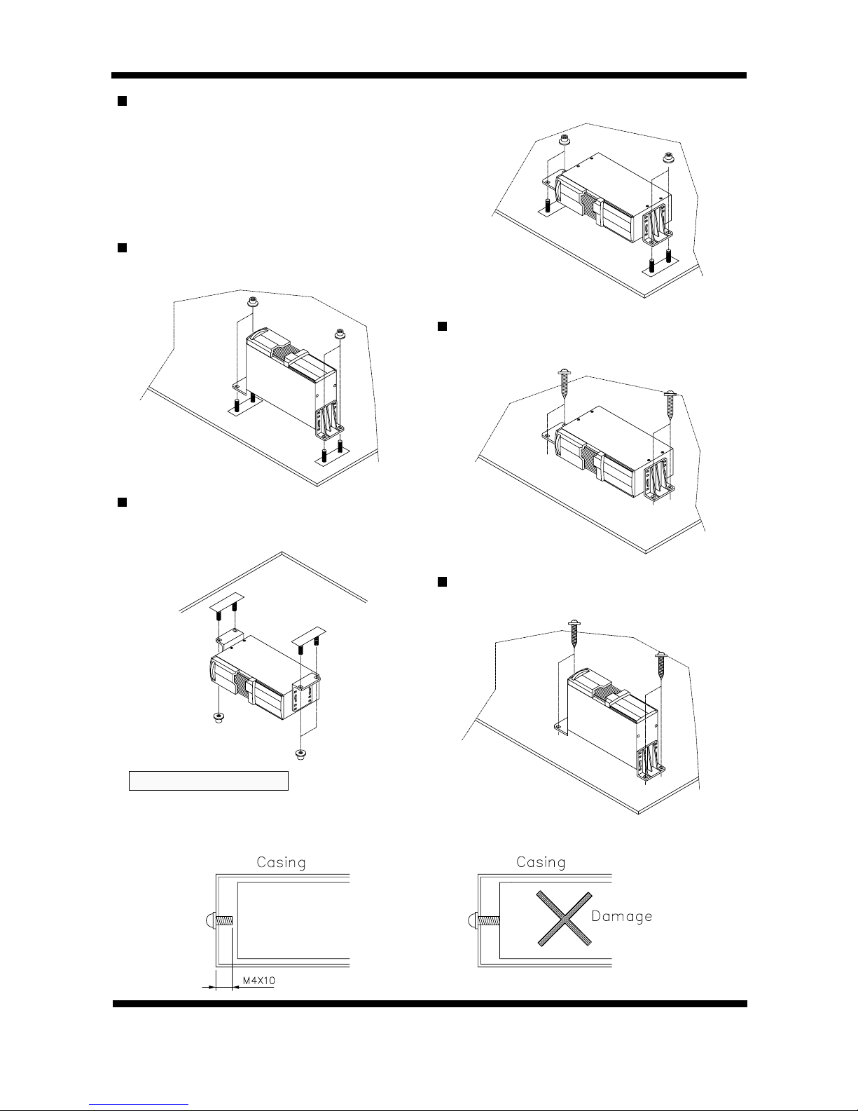
HORIZONTAL POSITION INSTALLATION (WITH BRACKET STUD)
VERTICAL POSITION INSTALLATION
(WITH BRACKET STUD)
HORIZONTAL POSITION INSTALLATION
(WITHOUT BRACKET STUD)
SUSPENDED POSITION INSTALLATION
(WITH BRACKET STUD)
VERTICAL POSITION INSTALLATION
(WITHOUT BRACKET STUD)
- 4 -
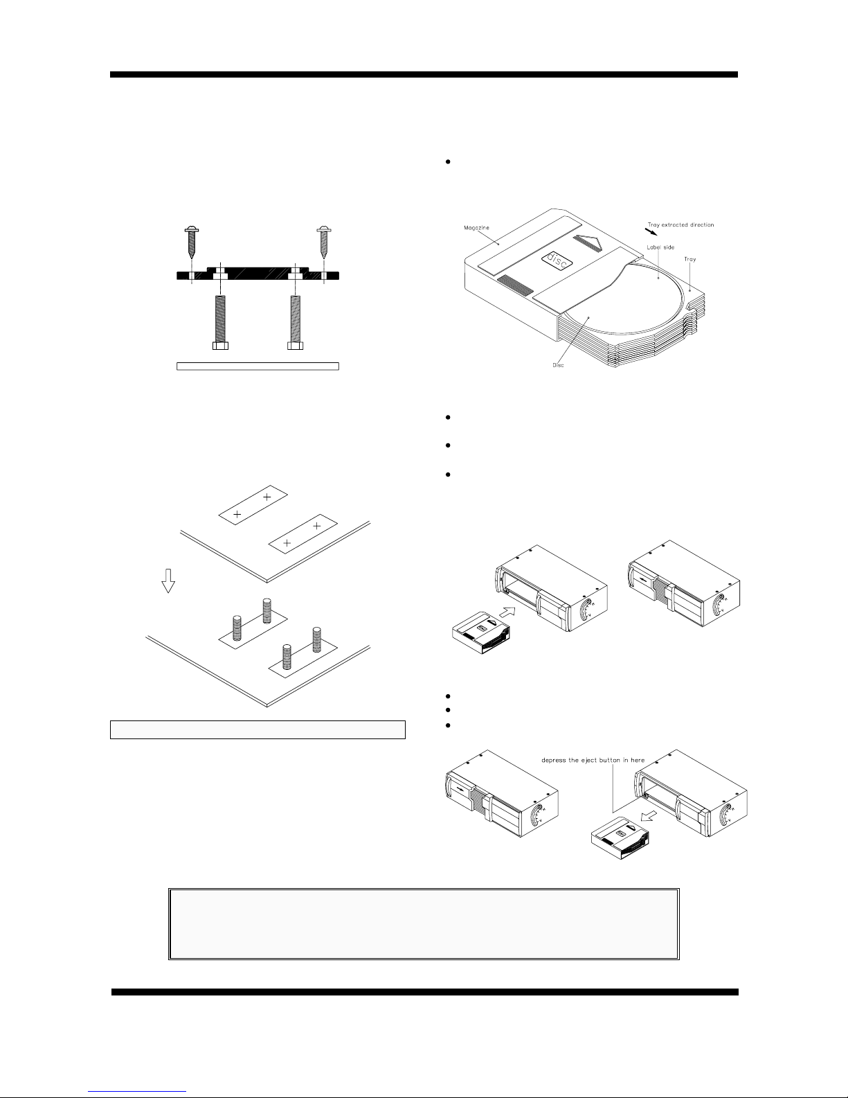
Use the wing nut to hold in place the
installation bracket with bolt(M6 x 25) to the
installation bracket, which is attached to the
unit. Then affix the cushion rubber.
Holes with the “H” marks are to be used for
horizontal or suspending and “V” for vertical
installation.
1.
Only the provided screws and brackets should be used during installation. Using
screws other than those specified will cause damage.
2. Before installation, check that there is no harness at the back when making a hole
on the dashboard.
Dangerous Installation

DAEWOO
3. INSTALLATION METHOD
(HOW TO INSTALL THE UNIT)
- 5 -
REMOVE TRANSIT SCREW 3 EACH BEFORE INSTALLATION
PART BRACKET DASH(L TYPE) ADHERE TO THE UNIT
After Setting the installation selector levers both sides(left, right)
SETTING THE INSTALLATION SELECTOR LEVERS ADJUST FOR UNIT (PRIOR TO INSTALL)
HORIZONTAL VERTICAL DECLINING
After Select Mark Hole(1), (2), (3)
The unit fasten by the screw(M4 x 10)
After Select Mark Hole (4)
The unit fasten by the screw(M4 x10)
After Select Mark Hole (2)
The unit fasten by the screw(M4 x 10)
DAEWOO
4.INSTALLATION METHOD
(HOW TO INSTALL THE VEHICLE)
5.PREPARATIONS
- 6 -
Should be determined before the unit install under
carpet.
Adjust the installation bracket with bolts to suit the place
of installation.
1.Remove the floor carpet and decide on the place to
install.
2.Remove the separator of the cushion rubber that is
attached to the installation bracket with bolt and install
accordingly.
3.Align the unit with the bolts and secure it with the wing
nuts.
1.USAGE OF MAGAZINE (To load the discs)
Load the discs with the labels facing upwards, as
shown in the diagram.
2.TO LOAD THE MAGAZINE
Slide the sliding door to the right until it is completely
latched on.
Load the magazine in the direction as shown in the
diagram. push it in until is locked into the unit.
After the magazine has been loaded, close the sliding
door.
(If not close sliding door, Dirt or dust entering it will
cause damage)
3.TO REMOVE THE MAGAZINE
Open the sliding door and depress the eject button.
Remove the magazine when it has been ejected.
Close the sliding door.
Notes on handling the optical pick-up block or base unit
1.The laser diode in the optical pick-up block may suffer
electrostatic breakdown because of the potential
difference generated by the charged electrostatic
load,etc. on clothing and the human body.
2.During repair, pay attention to electrostatic breakdown
and also use the procedure in the printed matter which
is included in the repair parts.
3.The flexible board is easily damaged and should be
handled with care.
CAUTION:
USE OF CONTROLS, ADJUSTMENTS, OR PERFORMANCE OF PROCEDURES OTHER THAN
THOSE SPECIFIED HEREIN, MAY RESULT IN HAZARDOUS RADIATION EXPOSURE.
THE COMPACT DISC PLAYER SHOULD NOT BE ADJUSTED OR REPAIRED BY ANYONE
EXCEPT PROPERLY QUALIFIED SERVICE PERSONNEL.
DISASSEMBLY
DAEWOO
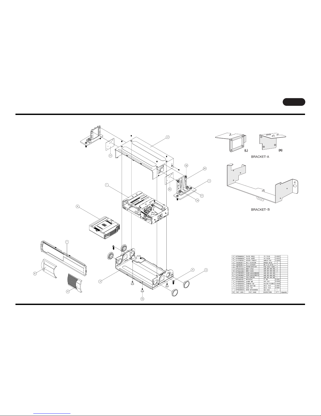
1. DISASSEMBLY
- 7 -
Size:A3
DAEWOO
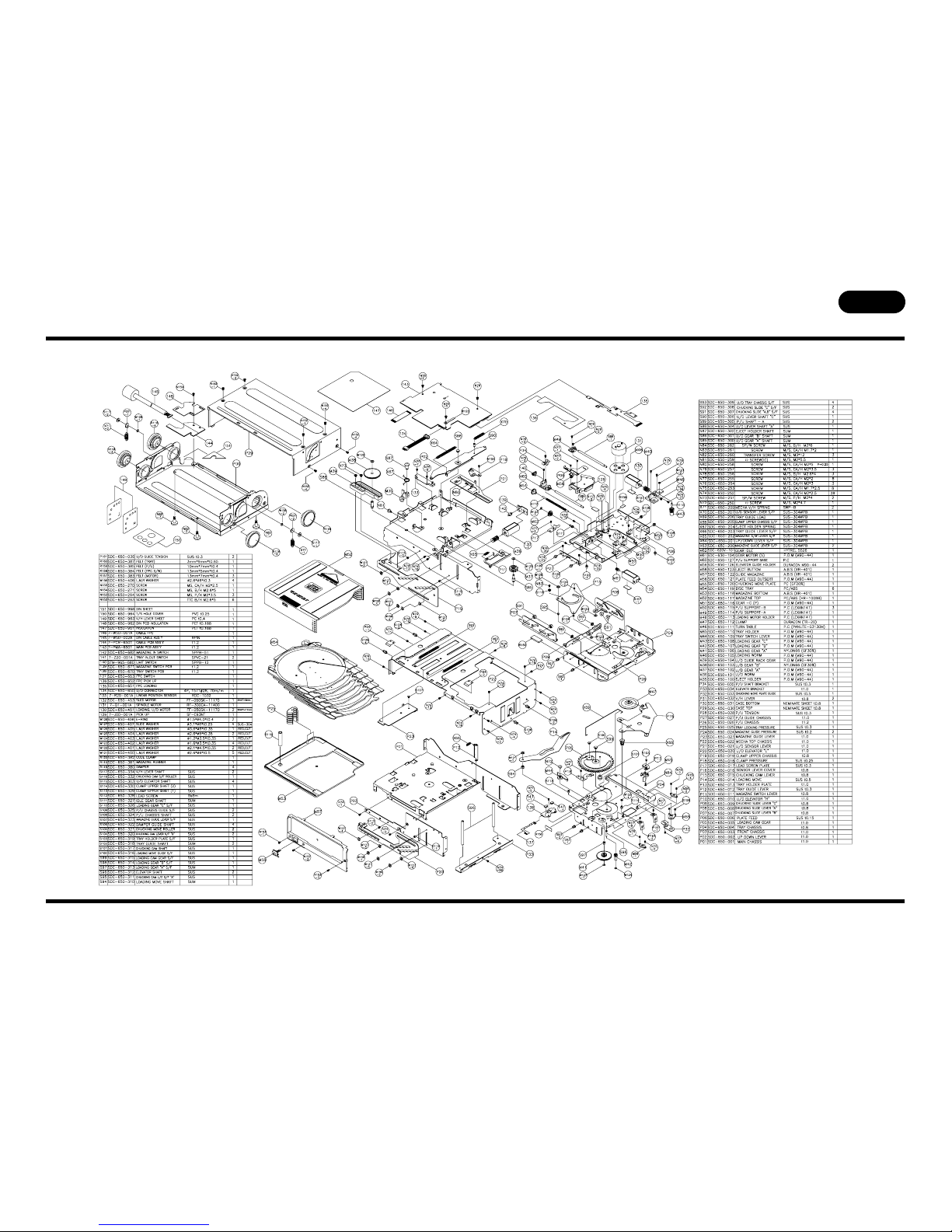
2. PICK-UP/MECHANISM/MAGAZINE ASSEMBLY
- 8 -
Size:A3
DAEWOO
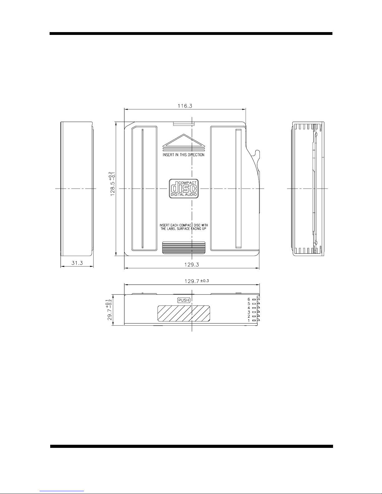
3. IDENTIFICATION OF MAGAZINE
- 9 -
Table of contents


