Dahua ISC-D218 User manual

Walk-through Metal Detector
Quick Start Guide
V1.0.0

Foreword
General
This manual introduces the functions and operations of the walk-through metal detector
(hereinafter referred to as "the Device").
Models
ISC-D206, ISC-D218
Safety Instructions
The following categorized signal words with defined meaning might appear in the manual.
Signal Words
Meaning
DANGER
Indicates a high potential hazard which, if not avoided, will result
in death or serious injury.
WARNING
Indicates a medium or low potential hazard which, if not avoided,
could result in slight or moderate injury.
CAUTION
Indicates a potential risk which, if not avoided, could result in
property damage, data loss, lower performance, or unpredictable
result.
TIPS
Provides methods to help you solve a problem or save you time.
NOTE
Provides additional information as the emphasis and supplement
to the text.
Revision History
Version
Revision Content
Release Time
V1.0.0
First release.
November 2020
Interface Declaration
This manual mainly introduces the relevant functions when you use the Device. The
interfaces used for manufacture, returning to the factory for inspection, and locating fault are
not described in this manual. Please contact technical support if you need information about
these interfaces.
About the Manual
The manual is for reference only. If there is inconsistency between the manual and the
actual product, the actual product shall prevail.

III
We are not liable for any loss caused by the operations that do not comply with the
manual.
The manual would be updated according to the latest laws and regulations of related
jurisdictions. For detailed information, refer to the paper manual, CD-ROM, QR code or
our official website. If there is inconsistency between paper manual and the electronic
version, the electronic version shall prevail.
All the designs and software are subject to change without prior written notice. The
product updates might cause some differences between the actual product and the
manual. Please contact the customer service for the latest program and supplementary
documentation.
There still might be deviation in technical data, functions and operations description, or
errors in print. If there is any doubt or dispute, we reserve the right of final explanation.
Upgrade the reader software or try other mainstream reader software if the manual (in
PDF format) cannot be opened.
All trademarks, registered trademarks and the company names in the manual are the
properties of their respective owners.
Please visit our website, contact the supplier or customer service if there is any problem
occurring when using the device.
If there is any uncertainty or controversy, we reserve the right of final explanation.

Important Safeguards and Warnings
This chapter describes the contents covering proper handling of the Device, hazard
prevention, and prevention of property damage. Read these contents carefully before using
the Device, comply with them when using, and keep the manual well for future reference.
Operation Requirement
Do not place or install the Device in a place exposed to sunlight or near the heat source.
Keep the Device away from dampness, dust or soot.
Keep the Device installed horizontally on the stable place to prevent it from falling.
Do not drop or splash liquid onto the Device, and make sure there is no object filled with
liquid on the Device to prevent liquid from flowing into the Device.
Install the Device in a well-ventilated place, and do not block the ventilation of the
Device.
Operate the Device within the rated range of power input and output.
Do not disassemble the Device.
Transport, use and store the Device under the allowed humidity and temperature
conditions.
Electrical Safety
Use the battery of specified manufacturer; otherwise there might result in explosion.
When replacing battery, make sure the same type is used. Improper battery use might
result in fire, explosion, or inflammation.
Always replace with the same type of batteries.
Use the recommended power cables in the region and conform to the rated power
specification.
Use the power adapter provided with the Device; otherwise, it might result in people
injury and device damage.
The power source shall conform to the requirement of the Safety Extra Low Voltage
(SELV) standard, and supply power with rated voltage which conforms to Limited power
Source requirement according to IEC60950-1. Please note that the power supply
requirement is subject to the device label.
Connect the Device (I-type structure) to the power socket with protective earthing.
The appliance coupler is a disconnection device. When using the coupler, keep the angle
for easy operation.

I
Table of Contents
Foreword................................................................................................................................................... II
Important Safeguards and Warnings....................................................................................................IV
1 Overview................................................................................................................................................. 1
Introduction ................................................................................................................................... 11.1 Detection Zones............................................................................................................................ 11.2 Technical Advantages................................................................................................................... 11.3 Application Scenario ..................................................................................................................... 21.4
2 Installation.............................................................................................................................................. 3
Checking List.................................................................................................................................32.1 Structure........................................................................................................................................ 32.2 Installation Environment................................................................................................................ 42.3 Installing the Device...................................................................................................................... 52.4
3 Configuration......................................................................................................................................... 9
ISC-D206 ...................................................................................................................................... 93.1 3.1.1 Configuration Panel............................................................................................................ 9
3.1.2 Basic Operations .............................................................................................................. 10
3.1.3 Configuring Function .........................................................................................................11
ISC-D218 .................................................................................................................................... 123.2 3.2.1 Configuration Panel.......................................................................................................... 12
3.2.2 Basic Operations .............................................................................................................. 13
4 Troubleshooting.................................................................................................................................. 16
Error Code (ISC-D218)............................................................................................................... 164.1 Troubleshooting........................................................................................................................... 174.2 Cybersecurity Recommendations................................................................................... 19Appendix 1

1
1 Overview
Introduction1.1
Walk-through metal detector is a high-performance security gate. The Device has high metal
detection sensitivity, light weight, strong anti-interference, and stable performance. It uses
high-strength special materials which is light-weighted and easy to transport and install. The
Device has a modular design and is manufactured on the unified assembly lines, so it can
ensure the good stability. It also delivers intuitive interface and simple use, so no operation
training is required to use it.
The Device can be widely used in sports meetings, conferences, schools and other occasions.
It adopts electromagnetic field to detect carry-on metal articles, and uses sound and light alarm
to indicate that the carry-on metal is more than a certain amount. It consists of a host, a
high-frequency signal generator, a signal receiver, and an infrared sensor, with a beautiful
appearance, strong metal detection capability, multiple detection zones, a unique Internet
remote management system, and light weight. It is currently a leading metal detection door in
the market.
Detection Zones1.2
Detection zones
Figure 1-1
No.
Number of Zones
1
33-zone
2
18-zone
3
6-zone
Technical Advantages1.3
Start-stop Technology

2
The IR units support manual start-stop technology for longer service life.
SensitivityAdjustable
The sensitivity of each detection zone can be adjusted as needed to meet different
sensitivity requirements of different zones.
Alarm
Light and sound alarm for sharp alert. The sound duration and volume can be adjusted as
needed.
Query
The system supports real-time query.
Detection Capability
60 to 100 people detected per min.
Filtering
Pre-define metal item weight, volume, size, part; exclude keys, jewelries, belt buckles and
more.
Security Protection
In line with EMC electromagnetic radiation standards and adopting weak magnetic field
technology, the device is harmless to cardiac pacemaker wearers, pregnant women, floppy
disks, film, and videotapes.
Application Scenario1.4
The Device is used to detect the metal items carried by the person going through the detection
door.
Typical application scenarios include:
Airports, ports: Passenger inspection.
Court: Visitors inspection.
Prison: Visitors inspection.
Meetings, public buildings, sports competitions: Participants inspection.
Power plant: Employees and visitors inspection.
Factory:Anti-theft.
Hotels, restaurants, entertainment venues, ballrooms: Visitors inspection.
The manufacturer is not responsible if the Device is used for purposes other than those
described above.
The design and manufacture of the Device is based on long-term practice and research. The
equipment is designed to be secure and, based on existing knowledge, does not pose any
health hazard to personnel passing through the security gates when operating in accordance
with the instructions.

3
2 Installation
Checking List2.1
After receiving your product, check against the table below. If there are any problems, contact
the after-sales service personnel.
Table 2-1 Checking list
Order
List
Description
1
Overall
packaging
Appearance
Obvious damage
Packaging
Accidental impact
Accessories (list of
accessories on
warranty card)
Complete or not
2
Host
Appearance
Obvious damage
Model
Whether consistent with the order
contract
Structure2.2
Dimensions (Unit: mm [inch])Figure 2-1

4
Table 2-2 Description
Parameter
Description
Overall Exterior Size
2170 mm ×845 mm ×465 mm
Passageway Interior Size
2015 mm ×688 mm ×368 mm
Packing Size
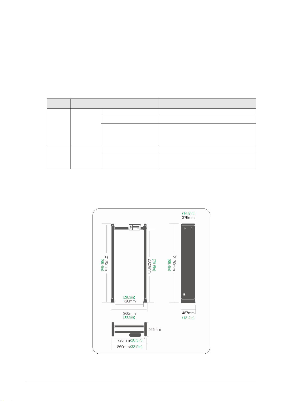
2409 mm ×868 mm ×303.5 mm
Net Weight
38 kg
Gross Weight
43 kg
Operating Voltage
90V–240V AC 50/60Hz
Power Consumption
13W
Operating Temperature
-20°C to +65°C (-4°F to +149°F)
Operating Humidity
0%–95%
Storage Temperature
-20°C to +70°C (-4°F to +158°F)
Storage Humidity
0%–90% RH
Installation Environment2.3
The ground is flat and sturdy
The ground should be flat and firmly supporting to prevent vibration. If there is a vibrating
metal structure under the ground, there can be unnecessary alarm when people passing
through the metal detection door.
Keep away from fixed metal objects
Large metal objects that are fixed or immobile should be at least 10 cm away from the
detection door (detecting large metal objects) because they might make the Device more
susceptible to vibration.
The distance in this section is the recommended distance. The actual installation distance
depends on the installation site conditions.
Keep away from moving metal objects
Large moving metal objects should be kept 0.5 m to 2 m away from the detection door to
avoid false alarms. Depending on the size of the metal object, the distance between the
moving metal object and the detection door might vary.
Keep away from radioactive electronic interference
The distance between the electronic interference source and the receiving coil should be
maximum. The recommended minimum distance is 0.5 m to 4 m. However, the actual
distance needs to be based on specific circumstances. For example, you can go through a
metal detector door with a source of interference until the best position is found.
Interference can occur from electronic control panels, radios and computers, image
displays, high-power motors and transformers, AC wires, transistor control circuits, flash
fluorescent tubes, arc welding equipment, and more.
Keep away from conductive electronic interference
Connect the power cord to a line that is not connected to other large loads, such as
high-power motors. Because they can cause a large power or voltage shock in the line.

5
Installing the Device2.4
Check whether the package is complete and open the box.Step 1 Open the boxFigure 2-2
Take out the left and right door panels from the box.Step 2 Take out door panelsFigure 2-3
Take out the manual, beam, host box, and power supply from the box.Step 3

6
Take out manual, beam, main box, and power supplyFigure 2-4
Follow the previous figure to prepare the door panels, beams, host box, and bolts.Step 4 Prepare the parts and the toolsFigure 2-5
Install the beams and the host box.Step 5 Install the beams and the host boxFigure 2-6

7
Connect the detection wire on the host box to the left and right door panels.Step 6 Connect the detection wireFigure 2-7
Stand the Device up.Step 7 Stand the Device up.Figure 2-8
Connect the power supply to the Device, and then turn on the power switch to start theStep 8 Device.

8
Start the DeviceFigure 2-9

9
3 Configuration
ISC-D2063.1
3.1.1 Configuration Panel
Single-zone panel (ISC-D206)Figure 3-1
Single-zone panel description (ISC-D206)Figure 3-2
No.
Name
①
Four-in-one digital tube.
②
Four-in-one digital tube.
③
Working indicator light.
④
Save and exit.
⑤
–
⑥
+
⑦
Program.
⑧
Pass indicator light.
⑨
Alarm indicator light.

10
4/6/L6-zone digital panel (ISC-D206)Figure 3-3
4/6/L6-zone panel description (ISC-D206)Figure 3-4
No.
Name
①
Four-in-one digital tube.
②
Four-in-one digital tube.
③
Working indicator light.
④
Power button.
⑤
–
⑥
+
⑦
Program.
3.1.2 Basic Operations
Starting the Device
Connect the power supply, press and hold the Reset/Switch button, and then the Device starts
and enters the working state, and shows "0000 0000".
Entering Password
When the screen shows "0000 0000", press Program, and then the screen shows "P 0000".
enter the password, press + to change the value of the corresponding bit (0 to 9 in cycle), press
To change the bit, press –. If the password is correct, press Program to go next; otherwise you
cannot go next, and the Device shows "P 0000".
Keep your password in mind.
Changing Password
When the screen shows "0000 0000" after power-on, press and hold Program for 3 s.Step 1 When the screen displays "P 0000", enter the old password (press –to change the bit,Step 2 and press + to change the value).
Press Program, and then the screen displays "C- - - - ". Press +, and then the screenStep 3 shows "P 0000".

11
Enter the new password (press –to change the bit, and press + to change the value),Step 4 and then press Program to save and go next.
Change passwordFigure 3-5
3.1.3 Configuring Function
Configure functions and parameters.
The values that you set at last are automatically saved when you go to the next interface.
Press Program to save when finishing each configuration.
Function configurationFigure 3-6
Table 3-1 Function description
No.
Function description
①
Number of passes.
②
Number of alarms.
③
Function configuration.
④
Parameter configuration.
To select a function, press PROG/Program.
To set a value, press to increase and to reduce.
Table 3-2 Single-zone function parameter configuration
Function
Parameter
Description
Enter password
—
—
Configure operating
frequency
1–50
50 levels available.
Configure detector
sensitivity
0–99
100 levels available.

12
Table 3-3 4/6/L6-zone function parameter configuration
Function
Parameter
Description
Configure security
level
1–20
20 levels available.
Configure operating
frequency
1–50
50 levels available.
Configure zone
sensitivity
0–200
200 levels available for Zone 1.
0–200
200 levels available for Zone 2.
0–200
200 levels available for Zone 3.
0–200
200 levels available for Zone 4.
0–200
200 levels available for Zone 5.
…
…
Configure the
duration of the alarm
sound
1–3
3 levels available.
Configure alarm
volume
0–2
2 levels available.
Configure alarm tone
1–10
10 levels available.
ISC-D2183.2
3.2.1 Configuration Panel
Panel (LED screen) (ISC-D218)Figure 3-7
Panel description (ISC-D218)Figure 3-8
No.
Name
②
Five-in-one green digital tube
②
Five-in-one red digital tube
③
Two-in-one green digital tube; Three-in-one red digital tube
④
+
⑤
–
⑥
Save and exit

13
No.
Name
⑦
Working indicator light
⑧
Program
⑨
Power button
Table 3-4 Functions description (ISC-D218)
Function
Description
Start
Press ⑨.
Power-on
Self-test
Self-tests 12 detectors on the left and right door panels after power-on. An
error message is prompted if a fault is discovered.
Self-tests the IR sensor after power-on. The error message LR ERR is
prompted if a fault is discovered.
Self-tests the SD card after power-on. The error message s d ERR is
prompted if a fault is discovered.
Enter
password
To enter the password, press ④to change the number of the corresponding bit
(0 to 9 in cycle). Press ⑤to change the bit. If the password is wrong, you get
the prompt C333. Press ⑥and enter the password again. Only when the
password is correct can you press ⑧to enter the parameter adjustment
interface.
Change
password
If you need to change the password, press ⑧for 5 s, and then the
corresponding bit began to flash. Press ④to change the value of the
corresponding bit (0 to 9 in cycle). Press ⑤to change the bit, and then you can
enter a new password. Press ⑧to save and enter the next level of setting.
3.2.2 Basic Operations
Configure functions and parameters.
Configure functionsFigure 3-9
Description
Figure 3-10
No.
Name
①
Number of passersby.
②
Number of alarm times.
③
Device setting display.
④
Function selection.
⑤
Parameter configuration.
To select a function, press ⑧.

14
To set parameter values, press ④to increase, and press ⑤to reduce.
Table 3-5 6/12/18-zone parameter configuration
Function
Parameter
Description
Configure operating
frequency
1–50
50 levels available.
Configure security level
0–99
100 levels available.
Configure zones
6/12/18
Three zone divisions are available.
Configure detector
sensitivity on the left
0–399
400 levels available for Detector 1.
0–399
400 levels available for Detector 2.
0–399
400 levels available for Detector 3.
0–399
400 levels available for Detector 4.
0–399
400 levels available for Detector 5.
…
…
Configure detector
sensitivity on the right
0–399
400 levels available for Detector 1.
0–399
400 levels available for Detector 2.
0–399
400 levels available for Detector 3.
0–399
400 levels available for Detector 4.
0–399
400 levels available for Detector 5.
…
…
Configure alarm volume
0–99
100 levels available.
Configure alarm tone
0–99
100 levels available.
Configure the duration of
the alarm sound
0–99
100 levels available.
Configure scenarios
1–72
72 scenarios available.
Configure column light
Ld 0 by
default
Change to Ld 1 when the left and right door
column lights are reversed.
Battery level
0–100
Displays battery level.
Automatic frequency
hopping
1–50
Automatically applies the suitable frequency.
Configure IR on/off
—
4 IR modes available.
Change password
***
Change password.
Table 3-6 Scenario number
No.
Scenario
No.
Scenario
No.
Scenario
1
Court
25
Celebration
49
Embassy
2
Prison
26
Entertainment venue
50
Power plant
3
Procuratorate
27
Performance venue
51
Hotel
4
Customs
28
KTV
52
Swimming pool
5
Border
29
Bar
53
Public security
bureau
6
Government buildings
30
Shopping mall
54
Bureau of letters and
visits
7
Airport
31
Fire fighting
55
Drug treatment center
8
High-speed rail
station
32
Ammunition depot
56
Exam place

15
No.
Scenario
No.
Scenario
No.
Scenario
9
Railway station
33
Gold and silver
jewelry
57
Courtroom
10
Bus station
34
Electroplating plant
58
Food factory
11
Wharf
35
Die casting
59
Bank.
12
Reeducation-through-
labor center
36
Precious metal
60
Vault
13
Printing plant
37
Communication room
61
Convention and
Exhibition Center
14
Metals factory
38
Meeting room
62
Subway station
15
Electronics factory
39
VIP room
63
Villa
16
Precision instrument
factory
40
Office
64
Community
17
Industry mine
41
Rescue station
65
Opera house
18
Oil depot
42
Club
66
Cinema
19
Research and
development center
43
Library
67
School
20
Archives office
44
Radio and television
station
68
Laboratory
21
Museum
45
Hospital
69
Detention house
22
Safe room
46
Weather stations
70
Asylum
23
Gym
47
Radar station
71
Gallery
24
Venue
48
Troops base
72
Amusement park
Table of contents
Other Dahua Metal Detector manuals
Popular Metal Detector manuals by other brands

Equinox Systems
Equinox Systems 800 Settings and Startup Procedure

Nokta
Nokta FORS Gold user manual

Minelab
Minelab F3 Operation manual

Powerfix Profi
Powerfix Profi KH 2902 operating instructions

Ceia
Ceia THS/21E Instruction manual for installation, use and maintenance

Fisher Labs
Fisher Labs CZ-3D operating manual