manuals.online logo
Brands
  1. Home
  2. •
  3. Brands
  4. •
  5. Daikin
  6. •
  7. Air Conditioner
  8. •
  9. Daikin ExtendAire IM 871-3 Instruction Manual

Daikin ExtendAire IM 871-3 Instruction Manual

General
Proper installation of the ExtendAire conditioner described
herein requires strict adherence to these installation
instructions.
Description
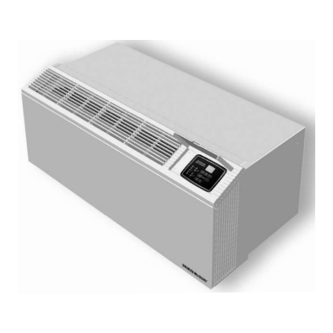
The ExtendAire conditioner is a cabinet extension kit designed
to provide balanced heating and cooling in two rooms using a
single Incremental conditioner. Components of the ExtendAire
are shown in Figure 1 and listed in Table 1.
Unpacking
Open the carton and check the contents. Report missing or
damaged parts to the carrier immediately.
!
CAUTION
Sharp metal edges are a hazard, use care when servicing to
avoid contact with them.
Applied PTAC ExtendAire™ for Models PDAE/PDHE
& PDAF/PDHF & Optional Boost Fan Installation
For Adjoining Room Applications
Installation & Maintenance Data IM 871-3
Group: Applied PTAC/HP
Part Number: 910116725
Date: October 2011
Figure 1: ExtendAire Component Descriptions
1. End Cap
2. 3' Extension Section
3. Shelf Discharge Section
4. Primary Discharge Section
5. Trim Piece
Table 1: ExtendAire Duct Extension Option
Description Quantity in
Each Package Part Number
Primary Discharge Section11 910106134
Shelf Discharge Assembly - Primary Discharge Section11
Shelf Discharge Assembly - 3-Foot Extension Section 1
Shelf Discharge Assembly - Shelf Discharge Section 1 910106137
Shelf Discharge Assembly - Trim Piece 2
Shelf Discharge Assembly - End Cap 2
Side Wall Outlet Assembly2- Primary Discharge Section1 1
Side Wall Outlet Assembly2- 3-Foot Extension Section 1 910106138
Side Wall Outlet Assembly2- Trim Piece 1
Side Wall Outlet Assembly2- End Cap 1
Notes: 1Control door and end cap are included in Primary Discharge Section.
2Discharge grille in adjoining room to be supplied by others. Additional 3-foot extension sections must be ordered in
packages as shown in Table 2.
Table 2: Supplementary Accessories
Description Quantity in
Each Package Part Number
3-Foot Extension Section Pack - 3-Foot Extension 2 061389601
3-Foot Extension Section Pack - Trim Piece 2
NOTICE
When a 3 foot (or greater) extension section is added to the pri-
mary discharge section, the (optional) boost fan is recommend-
ed. The Boost Fan operates when the indoor fan operates, to
assist unit airow into the adjoining room.
©2013 Daikin Applied • www.DaikinAP.com • (800) 432-1342
Page 2 of 12 M 871-3
3. Bend the hold down tabs on the underside of the cabinet/
wall sleeve grille tray and control door assembly 90º and
remove grille tray (Figure 4).
Figure 4: Typical Wall Construction Types
Bend Grille Tray
Tabs 90º to Remove
Grille Tray
NOTICE
If the optional boost fan is to be installed, install it now, referring to
"ExtendAire™ (Optional) Boost Fan Installation Procedure Com-
mon to Models PDAE/PDHE and PDAF/PDHF" on page 8
If the optional boost fan will not be installed continue ExtendAire
installation as follows.
Note: Before installing mounting brackets be sure they are
assembled as shown in Figure 5 detail.
4. Remove the grilles at the right and left ends of the primary
discharge section (Figure 5). Position Primary Discharge
Section on top of room cabinet (Figure 5). Through the
openings provided by the removed grilles, position the
mounting brackets at each end of the primary discharge
section (Figure 5).
5. Position the short (bottom) mounting bracket channel so
the tabs on each end catch the underside of the grille tray
of the cabinet/sleeve (Figure 5). The long (top) bracket
channel will sit on top of the turned anges of the Primary
Discharge Section (Figure 5).Adjust the bracket position
and tighten the Phillips head screw on top of the mounting
bracket to secure the discharge section to the cabinet/wall
sleeve.
Note: Be sure the primary discharge section is positioned
evenly end-to end with the cabinet/wall sleeve and that
it is aligned squarely with the front edge of the cabinet/
wall sleeve
!
CAUTION
ExtendAire & Optional Boost Fan
Installation Procedure Models PDAE
and PDHE
Installation and maintenance is to be performed only by qualied
personnel who are familiar with, and in compliance with state, lo-
cal and national codes and regulations, and experienced with this
type of equipment. Sharp edges and coil surfaces are potential
injury hazards. Avoid contact with them.
1. Remove front panel by removing the two screws located
along the top edge of the panel below the cabinet front edge
at the right and left corners (Figure 2). Tilt the top of the
panel out and lift up- and out of slots in the cabinet bottom.
Note: Set front panel aside and retain screws for reinstallation
Figure 2: Remove screws holding front panel, tilt out and
lift up- and out of slots in cabinet/wall sleeve bottom
Remove screws securing front panel
2. Remove chassis from the cabinet/wall sleeve by pulling
and sliding it out (Figure 3).
Note: Do not pull on coils, discharge air frame or critical
components that can be bent or damaged. The drain
pan may be used for pulling the chassis out of the
cabinet.
Figure 3: Slide the chassis out of the cabinet/wall sleeve
IM 871-3 Page 3 of 12
Relocating the Control Pad
Before reinstalling the chassis into the cabinet/wall sleeve, do
the following:
1. Locate the retaining clips (see Figure 7 on page 4)
holding the control pad to the chassis. Release the clips on
the Control Pad and set pad on chassis.
2. Slide the chassis into the cabinet/wall sleeve.
3. Lift the primary discharge section control door and angle
the control pad up and through the primary discharge
section control door opening. Check the communication
cable for proper connection to the Touchpad and the control
board.
Figure 5: Position and tighten screws on mounting brackets to secure primary discharge section to cabinet/wall sleeve.
Locate Right and Left Mounting Bracket
Primary Discharge Section
Mounting Bracket Assembly
Mounting Bracket Detail
4. Snap control pad into the primary discharge section control
pad opening.
To continue the ExtendAire installation refer to "ExtendAire™
Installation Procedure Common to Models PDAE/PDHE and
PDAF/PDHF" on page 6.
Page 4 of 12 M 871-3
ExtendAire & Optional Boost Fan
Installation Procedure Models PDAF
and PDHF
Note: For Flat Top ExtendAire installation, the wall sleeve
must extend a minimum of 2.5" into the space, through
the nished wall, to allow proper Primary Discharge
Section installation.
1. Remove front panel by lifting straight up until the panel
anges clear the anges on the wall sleeve (Figure 6).
Note: Set front panel aside for reinstallation
Figure 6: Lift front panel up until it clears the flanges on
the wall sleeve
Lift Front Panel straight up until it
clears the anges on the cabinet wrap
2. Remove the touchpad control bezel by releasing the plastic
clips located on the underside of the touchpad control
opening. Unplug the touchpad communication cable from
the control box (Figure 7). Set aside for reinstallation.
Figure 7: Remove the touchpad control bezel and unplug
the communication cable
Release the tabs on the
touchpad bezel from the
underside of the touchpad-
control opening
Unplug the touchpad com-
munication cable from the
control board
3. Remove the two (2) screws located at each end of the
cabinet wrap securing it to the wall sleeve. Lift slightly,
and pull the cabinet wrap away from the unit chassis/wall
sleeve (Figure 8).
Figure 8: Remove two (2) screws securing the cabinet wrap
to the wall sleeve, lift slightly, and pull away cabinet wrap
Remove two (2) screws securing
the cabinet wrap
4. Bend the hold down tabs on the underside of the cabinet
wrap grille tray/control door assembly 90º, and remove
grille tray (Figure 9).
Figure 9: Bend Tabs on the underside of the cabinet
Bend Grille Tray Tabs 90º
NOTICE
If the optional boost fan is to be installed, install it now, referring to
"ExtendAire™ (Optional) Boost Fan Installation Procedure Com-
mon to Models PDAE/PDHE and PDAF/PDHF" on page 8
If the optional boost fan will not be installed continue the
ExtendAire installation as follows.
5. Reinstall the cabinet wrap to the wall sleeve.
Note: Before installing the mounting brackets for the
ExtendAire primary discharge section be sure they are
assembled as shown in Figure 10 detail.
IM 871-3 Page 5 of 12
6. Remove the grilles at the right and left ends of the primary
discharge section (Figure 10). Position Primary Discharge
Section on top of room cabinet. Through the openings
provided by the removed grilles, position the mounting
brackets at each end of the primary discharge section.
7. Position the short (bottom) mounting bracket channel so
the tabs on each end catch the underside of the grille tray
of the cabinet/sleeve (see Figure 10 detail). The long (top)
bracket channel will sit on top of the turned anges of the
Primary Discharge Section.Adjust the bracket position
and tighten the Phillips head screw on top of the mounting
bracket to secure the discharge section to the cabinet.
NOTICE
If an ExtendAire boost fan is installed, it's power cord will pass
through the primary discharge section and over the mounting
brackets, and not underneath.
Note: Be sure the primary discharge section is positioned
evenly end-to end with the cabinet/wall sleeve and that
it is aligned squarely with the front edge of the cabinet/
wall sleeve
8. Reinstall the touchpad controller by plugging in the
communication cable into the receptacle in the control
board. Snap the bezel into the control door opening (Figure
11).
Figure 10: Position and tighten screws on mounting brackets to secure primary discharge section to cabinet/wall sleeve
Locate Right and Left Mounting Bracket
Primary Discharge Section
Mounting Bracket Assembly
Mounting Bracket Detail
Figure 11: Reinstall the touchpad communication cable
and the touchpad bezel
Reinstall the touchpad
control bezel into the
control door opening
Reinstall the touch-
pad communication
cable to the control
board
Go to page 6 and continue installation of ExtendAire compo-
nents.
Page 6 of 12 M 871-3
Figure 12: Typical Wall Construction Types
Primary Discharge
11" Section Primary Discharge
11" Section
8.5"
13.75"
5.25"
8.75"
3"
12"
23.5"
8.75"
11.5"
1.25"
*12" Wall 8.5" Wall
Note: *12" Wall Requires a 14.75" Deep Wall Sleeve
ExtendAire™ Installation Procedure
Common to Models PDAE/PDHE and PDAF/
PDHF
Locating the Duct Rough Opening
1. Based on the ExtendAire duct configuration, rough out a
hole at the correct position in the partition (that separates
the two spaces to be conditioned) to accept the 4½" × 11"
duct. Be sure the opening is level in relation to the primary
discharge section and square to the cabinet/wall sleeve.
Refer to the specic conguration for installation details.
Note: Upon completion of the selected conguration, refer to
steps 2, 3 and 4 on page 7.
Conguration 1
Shelf Discharge Assembly (Refer to Figure 13)
a. Butt end of one “L” shaped piece of 3' Extension Section
against Primary Discharge Section.Attach to wall with
screws or nails.
b. Snap second “L” shaped piece of 3' Extension Section into
section mounted on wall.
Note: When more than one 3' Extension Section is required,
repeat steps (a) and (b) for each section.
c. Repeat steps (a) and (b) for Shelf Discharge Section,
insuring that louvered section faces up.
d. Snap end caps into place on end of primary Discharge
Section and Shelf Discharge Section.
Note: To complete installation, refer to steps 2, 3 and 4 on
page 7.
Figure 13: Shelf Discharge Assembly Details
IM 871-3 Page 7 of 12
Conguration 2
Side Wall Outlet Assembly (Refer to Figure 14)
a. Butt end of one “L” shaped piece (rear half) of 3' Extension
Section against Primary Discharge Section and Shelf
Discharge Section.Attach to wall with screws or nails.
b. Snap second “L” shaped piece of 3' Extension Section into
section mounted on wall.
Notes: 1. When more than one 3' Extension Section is
required, repeat steps (a) and (b) for each section.
2. The grille in the adjoining room must be
non-adjustable and have a minimum of 35 sq. in.
free area.
2. Determine capacity requirements from the "ExtendAire
Capacity Selection", Table 3, Table 4 or Table 5 and place
required number of active grilles in space provided in top
section. Fill in remaining openings with inactive (blank)
grilles. Keep active grilles to the right and inactive grilles
to the left (when facing unit).
3. Cover joints with trim pieces.
4. Make sure there is at least 35 sq. in. free area return air
opening from adjoining room. Undercut door or provide
louver to provide return air.
Figure 14: Side Wall Outlet Assembly Details
ExtendAire Capacity Selection
Table 3: ExtendAire Capacity Selection1
Primary Primary Room Adjoining Room Approximate
Active Approximate Approximate Total System
Grilles Capacity % Capacity % CFM
560% 40% 302
Table 4: Side Wall Outlet Assembly – with Boost Fan
Primary Primary Room Adjoining Room Approximate
Active Approximate Approximate Total System
Grilles Capacity % Capacity % CFM
320% 80% 334
430% 70% 374
540% 60% 410
Table 5: Shelf Discharge Assembly – with Boost Fan
Primary Primary Room Adjoining Room Approximate
Active Approximate Approximate Total System
Grilles Capacity % Capacity % CFM
440% 60% 311
550% 50% 356
Note: 1 Refer to current product bulletin for total heating and
cooling capacities
Page 8 of 12 M 871-3
ExtendAire™ (Optional) Boost Fan
Installation Procedure Common to Models
PDAE/PDHE and PDAF/PDHF
Parts in Kit
1. Boost Fan (1)
2. Motor Wire Harness (1)
3. Zip Tie Mounts (3)
4. Zip Ties (3)
5. Wire Butt Connectors (2)
6. Top Mount Access Door (1) (Provided only with kits
910118056, 910117228 and 910118057 for retrofit
purposes)
Required Tools
● 1/4" Hex driver & 5/16" Hex driver
● Wire Cutters/Wire Strippers
● Terminal Crimper
Procedure
1. Disconnect power.
2. Remove front panel.
a. For PDAE/PDHE unit refer to instruction #1 on how to
remove the front panel on page 2 and Figure 2 on
page 2
b. For PDAF/PDHF unit refer to instruction #1 on how to
remove the front panel on page 4 and Figure 6 on
page 4
3. Remove unit chassis from wall sleeve.
a. For PDAE/PDHE unit refer to instruction #2 on how to
remove the chassis on page 2 and Figure 3 on page
2
b. For PDAF/PDHF unit refer to instruction #2 & #3 on
how to remove the cabinet wrap on page 4 and also
Figure 7 and Figure 8 on page 4. To remove the
chassis remove screws at locations shown in
Note: After completing steps 2a or 2b and 3a or 3b, continue
the Boost Fan installation as follows:
Figure 15: Remove the two (2) screws holding control box
to the chassis
Remove two (2) screws
holding control box
assembly to chassis
Control Box Assembly
4. Remove the two (2) screws holding the control box to the
chassis as shown in Figure 15.
5. Carefully tilt control box out, until resistance is felt from
the attached wiring. Do not pull excessively on control
box that could strain or damage wiring. Unplug the three
(3) terminal connectors located along the top of the board
(Figure 16). In some cases, with the premium control
board, there may be ve (5) terminal connectors.
6. Remove the three (3) screws holding the control box cover
to the control box and remove cover (Figure 16).
Figure 16: Unplug terminal connectors located along top of
board and remove three (3) screws holding the control box
cover to the control box
Control Box
Remove the three
(3) screws holding
control box cover
to the control box
and remove
Remove the wire
connectors plugged
into the top of the
control board
IM 871-3 Page 9 of 12
7. Disconnect the wire connectors along the left side of the
control board as numbered 1, 2, 3, 4 , 5 & 6 in Figure 17.
Figure 17: Disconnect the wire connectors along the left
side of the control board, numbered 1, 2, 3, 4, 5 & 6
8. Cut the Orange and Purple wires on the Indoor Fan
Connector (labeled #4 in Figure 18), approximately 2" back
from the connector. Strip back 1/4" on each wire.
Figure 18: Cut two wires on the fan connector, (orange and
purple), 2 inches back from the board connector
9. Refer to Figure 19 and insert the end of the orange wire
(detached from the plug connector) into the kit-provided
butt connector, and crimp. In the opposite end of the butt
connector insert the orange wire (attached to the plug
connector) and the orange wire from the kit-provided fan
motor wire harness, and crimp. Repeat for Purple wire
(using pink wire from the kit motor wire harness).
Figure 19: Make wire connections between the indoor fan
plug wires and the boost fan motor wire harness
#4- Indoor Fan Connector
Premium
Control Board
#4- Indoor Fan Connector
cut orange & purple wires
2" back from plug
Premium
Control Board
Butt
Connectors
Attach ground wire
See Figure 20
White wire with
piggy-back connector
for L2 Standby
Page 10 of 12 M 871-3
14.Re-attach all sensors and connectors to the appropriate
terminals along the left side of the control board. Replace
the control box cover in reverse order as described in
Figure 16 on page 8.
NOTICE
Use a proper method of bundling and securing the wires and con-
nections so that they do not snag or pull while replacing the con-
trol box cover and control box.
15.Replace control box, performing step 4 in reverse order
while referring to Figure 15 on page 8.
16.Remove the ExtendAire primary discharge section from the
unit, referring to Figure 10 on page 5 assembly details.
17.Slide ExtendAire Boost Fan Assembly into 3' extension
section, with power cord directed toward unit control box,
while making sure to take care with the existing insulation
The Boost Fan Assembly should be positioned midway
inside the 3' extension section, (see Figure 22).
18.Remove backing from one (1) zip-tie mount and adhere it
approximately 10" away from where the power cord enters
the boost fan (to the inside-back wall of the 3' extension
section). Secure the cord at this point with a zip-tie (Figure
22). Place the two (2) remaining zip-tie mounts close to
the edge of the discharge opening on the unit. See Notice
below.
NOTICE
Be sure that the two zip-tie mounts along the unit discharge sec-
tion are not positioned too near or at the point where the primary
discharge mounting brackets are to be positioned. The boost fan
power cord will be routed over the top of the mounting brackets of
the primary discharge section as shown in Figure 22 detail.
19.If ExtendAire is installed as a right hand discharge, coil
excess boost fan power cord away from discharge opening.
20.Remove the LUI touchpad from the unit control door
opening.
21.If primary ExtendAire discharge section has a reach-
through style door, remove the discharge grille section by
carefully straightening tabs on the underside of the grille.
Refer to step 4 and Figure 9 on page 4 to reference
method for removing grille section, otherwise skip to step
24.
NOTICE
Refer to step 4 and Figure 9 on page 4 to reference method
for removing grille section.
22.Remove current door and replace with door provided in kit.
23.Re-install grille section in ExtendAire primary section and
bend tabs back into original position.
10.Feed the (green) ground wire from the boost fan motor
harness through one of the three wiring grommets at the
bottom section of the control box and attach it to the
existing ground screw as shown in Figure 20.
Note: for clarity, all wires not shown.
Figure 20: Attach ground wire at the existing ground screw
located on the bottom of the control box
Ground wire routed
through wiring grommet
to ground screw Ground screw
11. If the unit is provided with standby power, remove the wire
connector from the L2-STBY terminal and attach it to the
piggy-back terminal on the white wire of the boost fan
motor harness, as shown in Figure 21.
Figure 21: Attach existing L2-STBY wire to piggy-back
terminal on the white wire from the boost fan motor wire
harness
White wire with
piggy-back connector
attaches to L2-STBY
L2-STBY
Terminal
Premium
Control Board
If Standby power wire exists on L2-STNBY,
attach to white wire piggy-back connector
12.Attach the white wire connector with the piggy-back to L2-
STBY terminal on the board.
13.If the unit does not have standby power, remove the
protective plastic cap from terminal L2-STBY on the board
and attach the white wire connector from the boost fan
motor wire harness to the L2-STBY terminal. DO NOT cut
jumpers JW1 or JW2.
IM 871-3 Page 11 of 12
24.Reattach ExtendAire primary section to the unit. See step
7 and refer to Figure 10 on page 5 for installation
instructions. Re-attach the 3' extension to the primary
discharge section and through the adjoining room cutout.
25.Secure the boost fan power cord within the primary
discharge section with the two remaining zip-ties.
NOTICE
The boost fan power cord must run over the top of the primary
discharge section mounting brackets, see Figure 22 detail.
26.Reinstall unit chassis into wall sleeve, if removed.
27.Route the boost fan power cord plug through the discharge
air opening in the cabinet/wall sleeve. The plug should exit
along the side of the control box where it will plug into the
boost fan motor wire harness (See detail in Figure 22 and
Figure 23).
28.Connect the two Molex connectors inside the unit to
provide control to the boost fan (Figure 23).
29.Feed the LUI communication cable through the control
door opening in the primary discharge section and plug into
the COM terminal on the premium control board. Also,
re-connect the remaining connectors onto the appropriate
terminals at the top of the premium control board.
Figure 22: Boost Fan assembly details
Boost fan positioned
midway inside
extension section
Boost fan power cord
secured with two (2) zip
ties in primary section
Trim piece
Removed right end
and left end grilles
Boost fan power cord plug
Primary discharge air section
Detail
Zip-tie location (1) in
3' extension section
Figure 23: Make plug connection of boost fan to fan motor
Boost Fan power cord
connector into Fan
Motor wire harness
connector
30.Snap LUI touchpad control bezel into the opening of the
control access door.
31.Return the front panel to the cabinet/wall sleeve and restore
power to the unit.
Note: Boost fan will run whenever indoor fan is operational,
regardless of speed of indoor fan.
© 2013 Daikin Applied Applied • www.DaikinAP.com • (800) 432–1342 IM 871-3 / Page 12 of 12 (10/13)
Daikin Training and Development
Now that you have made an investment in modern, efcient Daikin equipment, its care should be a high
priority. For training information on all Daikin HVAC products, please visit us at
www.DaikinAP.com and click on training, or call 540-248-9646 and ask for the Training Department.
Warranty
All Daikin equipment is sold pursuant to its standard terms and conditions of sale, including Limited
Product Warranty. Consult your local Daikin Representative for warranty details. Refer to Form 933-
430285Y. To nd your local Daikin Representative, go to www.DaikinAP.com.
Aftermarket Services
To nd your local parts ofce, visit www.DaikinAP.com or call 800-37PARTS (800-377-2787). To nd
your local service ofce, visit www.DaikinAPcom or call 800-432-1342.
This document contains the most current product information as of this printing. For the most up-to-date
product information, please go to www.DaikinAP.com.
Products manufactured in an ISO Certied Facility.

This manual suits for next models

1

Other Daikin Air Conditioner manuals

Daikin FTXTP25M5V1B Product information sheet

Daikin

Daikin FTXTP25M5V1B Product information sheet

Daikin CTXG09QVJUW User manual

Daikin

Daikin CTXG09QVJUW User manual

Daikin RZQ24MVJU User manual

Daikin

Daikin RZQ24MVJU User manual

Daikin 2MXM40A2V1B User manual

Daikin

Daikin 2MXM40A2V1B User manual

Daikin EWAD TZ User manual

Daikin

Daikin EWAD TZ User manual

Daikin FXSQ-P7VEB Instruction manual

Daikin

Daikin FXSQ-P7VEB Instruction manual

Daikin FXMQ72MVJU User manual

Daikin

Daikin FXMQ72MVJU User manual

Daikin FTY22JVE1F User manual

Daikin

Daikin FTY22JVE1F User manual

Daikin FH(Y)35BJV1 User manual

Daikin

Daikin FH(Y)35BJV1 User manual

Daikin Altherma EHBH04+08DA Product information sheet

Daikin

Daikin Altherma EHBH04+08DA Product information sheet

Daikin RX15FVJU User manual

Daikin

Daikin RX15FVJU User manual

Daikin FTXTA30C2V1BB User manual

Daikin

Daikin FTXTA30C2V1BB User manual

Daikin FFQ25B9V Instruction manual

Daikin

Daikin FFQ25B9V Instruction manual

Daikin B-Series User manual

Daikin

Daikin B-Series User manual

Daikin Maverick I Manual

Daikin

Daikin Maverick I Manual

Daikin FTX50GV1B User manual

Daikin

Daikin FTX50GV1B User manual

Daikin FTKD24HV2S User manual

Daikin

Daikin FTKD24HV2S User manual

Daikin FXA20LVE User manual

Daikin

Daikin FXA20LVE User manual

Daikin Air Conditioner User manual

Daikin

Daikin Air Conditioner User manual

Daikin EBLA08E23V3 User manual

Daikin

Daikin EBLA08E23V3 User manual

Daikin ARXN25N5V1B9 User manual

Daikin

Daikin ARXN25N5V1B9 User manual

Daikin FTXP50N2V1B User manual

Daikin

Daikin FTXP50N2V1B User manual

Daikin ATXS20E2V1B User manual

Daikin

Daikin ATXS20E2V1B User manual

Daikin FCQ71DAV3B User manual

Daikin

Daikin FCQ71DAV3B User manual

Popular Air Conditioner manuals by other brands

Frigidaire FFPA1422R1 use & care

Frigidaire

Frigidaire FFPA1422R1 use & care

York F2FP040H06 User's information manual

York

York F2FP040H06 User's information manual

Frigidaire CRA073PU11 use & care

Frigidaire

Frigidaire CRA073PU11 use & care

Mitsubishi Electric Mr.Slim PUZ-SM100VKA Service manual

Mitsubishi Electric

Mitsubishi Electric Mr.Slim PUZ-SM100VKA Service manual

Gree E-TAC Installation and operation instructions

Gree

Gree E-TAC Installation and operation instructions

Honeywell CL30XC owner's manual

Honeywell

Honeywell CL30XC owner's manual

Friedrich CCW06B10B operating instructions

Friedrich

Friedrich CCW06B10B operating instructions

Tecumseh TC300 SERIES Operator's manual

Tecumseh

Tecumseh TC300 SERIES Operator's manual

Trane TTK060K4 Product bulletin

Trane

Trane TTK060K4 Product bulletin

Crosley 2020213A Use & care manual

Crosley

Crosley 2020213A Use & care manual

Frigidaire LRA257ST216 installation instructions

Frigidaire

Frigidaire LRA257ST216 installation instructions

PR KLIMA GPC10AL operating instructions

PR KLIMA

PR KLIMA GPC10AL operating instructions

DeLonghi EX Series Instructions for use

DeLonghi

DeLonghi EX Series Instructions for use

Samsung AQV12J Series user manual

Samsung

Samsung AQV12J Series user manual

GREE ELECTRIC GWH09TA-S3DNA1C Service manual

GREE ELECTRIC

GREE ELECTRIC GWH09TA-S3DNA1C Service manual

Hokkaido HKEI-HCNI 263 XR Service manual

Hokkaido

Hokkaido HKEI-HCNI 263 XR Service manual

Mitsubishi Electric MFZ-KA25VA Service manual

Mitsubishi Electric

Mitsubishi Electric MFZ-KA25VA Service manual

Panasonic CS-MKE7NKU Technical & service manual

Panasonic

Panasonic CS-MKE7NKU Technical & service manual

manuals.online logo
manuals.online logoBrands
  • About & Mission
  • Contact us
  • Privacy Policy
  • Terms and Conditions

Copyright 2025 Manuals.Online. All Rights Reserved.