10 IM 962-2
Installation
Installation
Order Parts
When reporting shortages or damaged parts, or when
ordering repair parts, give the complete unit model and serial
numbers which are stamped on the unit rating plate.
Standard Items
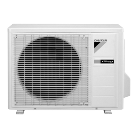
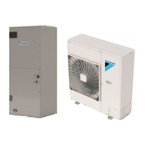
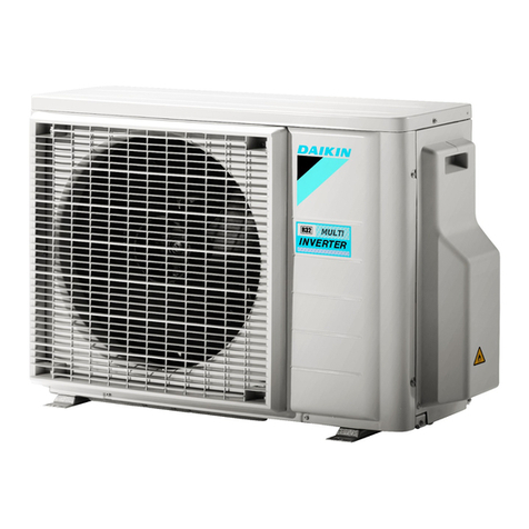
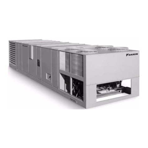
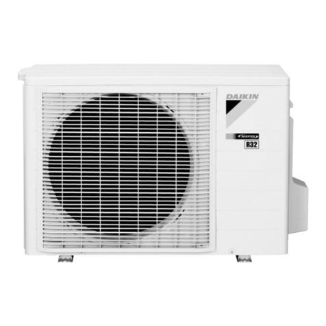
The condensing unit consists of a completely assembled
package which includes a compressor pack, condenser coils,
fans, fan motors, outdoor control box, factory wiring, factory
tubing and ttings.
Crankcase Heaters
These units are equipped with a crankcase heater that is
factory wired to operate whenever the main power supply
to the unit is “ON” and compressors are “OFF.” Before
starting the equipment after prolonged shutdown or at the
time of initial spring startup, be sure that the circuits to the
condensing units are closed for at least 24 hours.
Corrosive Environment
The metal parts of this unit may be subject to rust or
deterioration if exposed to a corrosive environment. This
oxidation could shorten the equipment’s useful life. Corrosive
elements include salt spray, fog or mist in seacoast areas,
sulphur or chlorine from lawn watering systems, and various
chemical contaminants from industries such as paper mills
and petroleum reneries.
If the unit is to be installed in an area where contaminants are
likely to be a problem, special attention should be given to the
equipment location and exposure.
• Avoid having lawn sprinkler heads spray directly on the
unit cabinet
• In coastal areas, locate the unit on the side of the
building away from the waterfront.
•Shielding provided by a protection, based on clearances
DANGER
Disconnect all power to unit before starting maintenance.
Failure to do so can cause electrical shock resulting in severe
personal injury or death.
Regular maintenance will reduce the buildup of contaminants
and help to protect the unit’s nish.
• Frequent washing of the cabinet, fan blade and coil
with fresh water will remove most of the salt or other
contaminants that build up on the unit.
• Regular cleaning and waxing of the cabinet with a good
automobile polish will provide some protection.
• A good liquid cleaner may be used several times a year
to remove matter that will not wash off with water.
Several different types of protective coatings are offered in
some areas. These coatings may provide some benet, but the
effectiveness of such coating materials cannot be veried by
the equipment manufacturer.
Installation General
The condensing unit should be installed outdoors. It should be
located as near as possible to the evaporator section to keep
connecting refrigerant tubing lengths to a minimum. The unit
must be installed to allow a free air ow to the condenser coils
If several units are installed adjacent to each other, take care
to avoid recirculation of air from one condenser to another.
In all installations, adequate space must be provided for
installation and servicing.
The unit must not be connected to any duct work. Do not
locate unit under a roof drip; if necessary, install gutters,
etc., to prevent water runoff onto the unit. To prevent air
recirculation, it is recommended that the unit not be installed
under an overhang. However, if this is necessary, allow a
minimum of 60" above the unit for air discharge
Figure 8: Clearances RCS 06F – 20F Service Clearances


