manuals.online logo
Brands
  1. Home
  2. •
  3. Brands
  4. •
  5. Daikin
  6. •
  7. Air Handler
  8. •
  9. Daikin Easdale 25 Manual

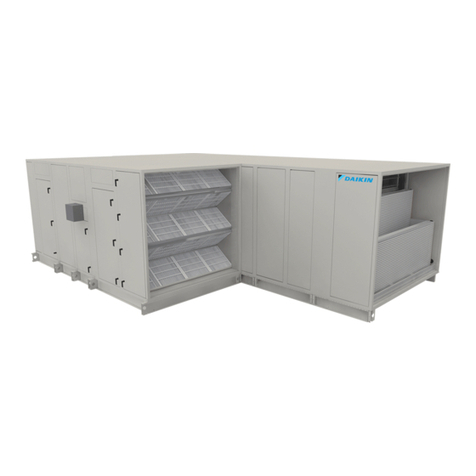
Daikin Easdale 25 Manual

REV A –PAGE 9. SECTION 11 ADDED. 11/03/14 Page 1 of 37
Installation, Operation and
Maintenance Instructions
For The Easdale 25 & 50
Air Handling Units
Daikin Applied (UK) Ltd.
REV A –PAGE 9. SECTION 11 ADDED. 11/03/14 Page 2 of 37
Contents Index
Page 3 - 5 Health and Safety
Page 4 Cautionary Notes
Page 5 Disposal of Redundant Materials
Page 6 Shipping
Page 7 - 8 Lifting, Off Loading and Handling
Page 8 Location
Page 9 Assembly
Page 9 Section Open Face Corner Bracing
Page 10 Fan Temporary Restraints
Page 11 - 12 Storage / Static Maintenance
Page 12 Standby Motors
Page 13 Electrical Connections
Page 13 Ductwork Connections
Page 14 - 16 Commissioning and Testing
Page 16 Drive Belts
Page 17 - 18 Belt Tensioning Instructions/ Pulley Alignment Instructions
Page 21 - 22 Maintenance Procedures
Component Installation & Maintenance:-
Page 23 Fans
Page 24 Electric Motors
Page 24 Electric Motors Lifting Beam
Page 24 - 26 Electric Coils
Page 26 - 28 Heating & Cooling Coils
Page 26 & 29 Drain Tray Connections & Drain Traps
Page 29 - 30 Condensate Removal from Steam Coils
Page 32 Plate Heat Exchangers
Page 32 Dampers
Page 32 - 33 Filters
Page 34 Gas Burners
Page 34 Humidifiers
Page 34 Inverters
Page 34 Thermal Wheels
Page 35 Fault Finding
Page 36 Invalidation of Guarantee
Page 36 Contact Telephone Numbers
Page 37 Environmental Information
Daikin Applied (UK) Ltd.
REV A –PAGE 9. SECTION 11 ADDED. 11/03/14 Page 3 of 37
Health and Safety
Unit Construction
All galvanised, stainless steel, plastisol & aluminium used in the construction of these
units is purchased and in line with the relevant British & European standards.
Working Conditions and Pre-Installation Check
This section deals with the hazards that could be encountered when any work is carried
out on the equipment for which this manual is written.
Therefore the following points should be observed to avoid any injuries or health
hazards.
The unit shall be checked to ensure that:
It is suitable for the electrical supply available.
It is suitable for the atmosphere or the environment in which it is to be used.
It is suitable for the working media, temperature and pressure for which it is to be used.
It is manually isolated from the mains supply before any work is carried out.
DO NOT enter the unit while the fans are running.
Electrical equipment is earthed to comply with all I.E.E. Regulations and local bye-laws.
All quoted fan volumes & noise levels are provided in accordance with relevant fan
manufactures standards and are subject to industrial accepted tolerances.
Insertion losses are derived from static tests carried out in accordance with
BS4718:1971.
Effective insertion loss in AHU application will be affected by airflow conditions/noise
regeneration and component losses.
The data should not be arithmetically subtracted from the fan Lw to obtain the inlet &
outlet levels. Reference must be made to Daikin Applied (UK) Ltd.
When starting the electric motor(s) the procedure as laid down in this manual is fully
carried out.
The procedure for removing and replacing belts and filter media (bags or panels) are
fully carried out as laid down in this manual or the supplier's literature.
Note:-
Daikin Applied (UK) Ltd.
REV A –PAGE 9. SECTION 11 ADDED. 11/03/14 Page 4 of 37
1) The equipment must only be installed or operated by trained and competent
personnel.
2) The equipment must only be used for its intended purpose and any deviations
from its intended use may result in an unsafe condition for which Daikin Applied
(UK) Ltd.will not be held responsible.
3) The equipment must not be used where flammable dust or vapours may be
present.
4) The equipment must not be modified in any way. Daikin Applied (UK) Ltd. will
not be held responsible for any unauthorised modifications.
5) Lists of recommended spares are available on request and any spare parts
should only be obtained from Daikin Applied (UK) Ltd.
Cautionary Notes
No part of the unit shall be dismantled until a careful study has been made of this
manual.
This manual deals in detail with shipping, installation, commissioning and servicing and
must be strictly adhered to.
Wherever any maintenance or work is done within the unit, the interior shall be left clean
and all access panels shall be correctly fastened.
Note! Before locking all access panels ensure that no personnel or tools etc are
inside unit
Bearing Damage - Cautionary Note
During the interval between delivery and commissioning the drive belts should be
slackened and the fan and motor shafts spun once every two (2) months ensuring that
they are not in the same angular position after rotation.
Water Treatment (Mandatory)
Check for any treatment that is required to the water supply for prevention of corrosion
and scaling of equipment. Information regarding the necessary action to be taken can
be obtained from the relevant Water Supply Authority, particulars of which can be found
in the Water Engineers Handbook yearly edition.
Daikin Applied (UK) Ltd.
REV A –PAGE 9. SECTION 11 ADDED. 11/03/14 Page 5 of 37
Safety Information
All Electrical work carried out on the Air Handling Units, must be in accordance with
the Manufacturers instructions and relevant codes & practices.

All work carried out on, or in, the Air Handling Units must be in accordance with the
client’s permit to work system.

Before starting the Air Handling Units for the first time ensure that all earthing bonds
have been made and securely fastened.

Before working on, or in, the Air Handling Units, ensure that all electrical connections
have been isolated and isolators padlocked in the OFF position.
Safety Information (continued)

Before starting the Air Handling Units, ensure that all access doors and panels are
closed and clamped shut.

When work is required inside the Air Handling Units allow at least two (2) minutes
after switching the power off before entering the Air Handling Units. This is to ensure
that all rotating parts have come to a rest.
Do not remove any drive guards unless the equipment is isolated and stationary.

Ensure that all guards are correctly replaced and secured before restarting the Air
Handling Units.
Disposal of Redundant Materials
All redundant materials must be disposed of in accordance with the relevant local and
national environmental regulations.
Daikin Applied (UK) Ltd.
REV A –PAGE 9. SECTION 11 ADDED. 11/03/14 Page 6 of 37
Shipping
Each unit and section will be clearly identified and each section shall be shipped as an
individual section unless otherwise stated on the General Arrangement (GA) drawing.
Each section is dispatched covered in shrink-wrapped polythene sheeting. All sharp
edges shall be protected with cardboard to stop the polythene sheeting from being
ripped. Once at Site the shrink-wrapped should be removed as it is not a protection
against the elements.
If the unit is left outside then it is the Customers responsibility to protect the unit.
Identification of units shall be placed on the outside of shrink-wrap.
Sections are normally supplied complete with an integral channel base. Should these
not be required e.g. in the case of stacked units, then the sections will be shipped on
wooden pallets.
Upon receipt of equipment a visual inspection should be made and any damage noted
on the delivery form. Particulars of any damage or short delivery should be endorsed by
the driver delivering the equipment.
No responsibility can be held for damage sustained during the unloading from the
delivery vehicle or on the site thereafter.
Any variation to the above will have cost implications. Should special arrangements or
packing be required then Daikin Applied (UK) Ltd. must be notified in sufficient time in
advance.
All claims for damage or short delivery should be advised to Daikin Applied (UK) Ltd. in
writing
within seven (7) days of receipt to the following address :-
Daikin Applied (UK) Ltd.
Bassington Lane
Cramlington
Northumberland
NE23 8AF
Daikin Applied (UK) Ltd.
REV A –PAGE 9. SECTION 11 ADDED. 11/03/14 Page 7 of 37
Lifting, Off Loading and Handling
Care should be taken during all handling of equipment to prevent damage. Estimated
weights of shipped sections are shown on the General Arrangement (GA) drawings.
The actual weight of the shipped sections is labelled on the polythene sheeting
It is recommended that if the units are shipped on wooden pallets that they are left in
place until the units have been correctly sited. This will help prevent site damage and
will aid handling. If this recommendation is not adhered to then it is not Daikin Applied
(UK) Ltd’s responsibility for any damage caused to the units.
1) All work must be in accordance with the Health and Safety at Work Act 1974,
relevant H.S.E. Guidance Notes and Codes of Practice. When cranes are used it is
recommended that the requirements of BS 7121 be observed.
Diagram 1 - Shows the lifting items required when lifting by crane.
Lifting, Off Loading and Handling (continued)
Daikin Applied (UK) Ltd.
REV A –PAGE 9. SECTION 11 ADDED. 11/03/14 Page 8 of 37
2) Only non-metal slings must be used. These must be used in conjunction with a
lifting frame / beam to ensure an even load distribution and correct positioning of
slings. Wooden packing pieces must be inserted between the sling and the
framework to avoid damage.
3) When units are mounted on a wooden pallet, they may be lifted either by a crane or
a fork lift truck, provided, in the case of the latter; it is within the limits of normal
good handling procedures.
4) The channel base, fitted underneath each section, is drilled to accept lifting bars.
When bars are used they must be mechanically locked in position to ensure that
they cannot move. The bars themselves must be both adequately sized and tested
to ensure that they are capable of safely handling the weight of the section. (See
Diagram 1)
5) All sections, particularly the fan sections, must remain level during lifting or
manhandling.
Under no circumstances should they be tilted onto their side.
6) If sections are either too heavy or too wide to use lifting bars then the channel base
is fitted with bolt on lifting brackets. Again non metal slings and lifting frame / beam
are to be used as stated above.
Location
When locating the Air Handling Unit ensure that:-
1) Sufficient space exists around the sections to enable them to be manoeuvred into
their final location.
2) Sufficient space exists around the unit to enable the filters to be removed and
access can be gained where required. It is recommended that full unit width
access be provided on one side of the unit adjacent to the fan and coil sections.
This is to enable the fans and coils to be removed should ever a fault develop.
3) The unit is installed at a height that allows the installation of the condensate drain
trap.
4) Supports are adequate for the weight of the unit.
5) The plinth, or fixing frame, upon which the unit is to be sited is firm and level. If not
then use packing shims to level the unit when locating.
Assembly
Daikin Applied (UK) Ltd.
REV A –PAGE 9. SECTION 11 ADDED. 11/03/14 Page 9 of 37
All fixing channels, clamps,hardware, etc., for connecting the sections together are
supplied by Daikin Applied (UK) Ltd. These are boxed separately and are placed inside
the fan section for shipment.
The assembly procedure is as follows:
1) Referring to the General Arrangement (GA) drawing, ensure the sections are in the
correct order of airflow, are correctly orientated and are central to each other.
2) Individual sections are shipped loose for site assembly by others and support legs
(if applicable) are supplied loose for site fitting by others.
3) Ensure that the sections are aligned and levelled to the tolerances as shown on
the Section to Section Assembly drawing A4-920058.
On some larger units, to aid stability during lifting and shipping, temporary
corner bracing is fitted to the open ends of a section as shown on drawing A4-
500646. The bracing must be removed prior to bringing together the joint faces of
adjacent sections. This is to allow the fitting of section to section joining
channels.
4) Ensure that the mating faces of each section are parallel to each other and that
there is contact with each face of the two sections.
5) Use an access door if possible to gain access to the joint for joining the two
sections together. Refer to the Section to Section Fixing Detail drawing A4-STS07
for INT50 unit or A4-STS09 for INT25 unit and the Assembly drawing for site fitting
of section to section joining for installation. If the joint is not accessible via an
access door then remove a side panel adjacent to the joint using a Philips head
screwdriver.
6) Replace all panels upon completion.
7) For weatherproof units see FWR01 for joint sealing, water shed etc.
8) Do not start unit up until at least 24 hours after all sections are assembled together
and the flush internal channels have been fitted inside the unit.
9) If the units are stacked then ensure that the top section is lifted onto the bottom
section in accordance with the previously listed lifting recommendations.
10) Fit the top section to the bottom section through the fixing holes in the top sections
channel base using self tapping screws and large outside diameter washers. If the
unit has a damper, or duct, between the top and bottom sections then refer to
drawing A4–EMP05 for details on the method of sealing and fixing
11) On multi deck units refer to EMP36 for unit fixing and clamping arrangement.
Daikin Applied (UK) Ltd.
REV A –PAGE 9. SECTION 11 ADDED. 11/03/14 Page 10 of 37
Fan Temporary Restraints
Fans are supplied with a fan discharge flexible connection and anti-vibration mounts
which have been factory installed. To prevent damage to these during transport,
temporary restraints are fitted to the fan base inside all fan sections. For details refer to
drawing A4-417645
These restraints must be removed after installation and before commissioning
and they should be returned to Daikin Applied (UK) Ltd.head office at
Cramlington.
Daikin Applied (UK) Ltd.
REV A –PAGE 9. SECTION 11 ADDED. 11/03/14 Page 11 of 37
Storage / Static Maintenance
For external storage, or storage in partly built plant rooms, the units must be protected
to stop the ingress of foreign material or water into the unit. Although covered in shrink-
wrapped plastic sheeting this is not intended for long-term storage and should be
removed as soon as the unit is off loaded. Units, therefore, should be more permanently
protected, either by tarpaulins or similar.
If this recommendation is not adhered to then it is not Daikin Applied (UK) Ltd’s
responsibility for any damage caused to the units.
The units must not be used as site storage chambers, or be used as work platforms.
Failure to prevent this can result in the unit becoming damaged.
If this recommendation is not adhered to then it is not Daikin Applied (UK) Ltd’s
responsibility for any damage caused to the units.
Every two (2) months the fan impeller / motor drive must be rotated by a third of a turn.
Failure to do this can invalidate the Daikin Applied (UK) Ltd warranty.
Unit Interior Surfaces
If ducting is not connected to the unit it is essential that all inlets and discharge
openings are completely sealed.
Unit Exterior Surfaces
The exterior shall be kept free from falling building materials, dampness or extreme cold
or heat. The unitexterior surfaces should be inspected on a monthly basis and any
signs of corrosion or damage treated immediately.
Belts and Pulleys
Should the units be unused for a period exceeding six (6) months then it is
recommended that the drive belts be removed and stored separately. The fan and
motor shafts must be rotated a third of a turn every two (2) months as before.
The belts should be removed from the pulleys and hung up and not exposed to
excessive heat or cold and kept free from dampness. Belt life is reduced over a long
period of non-use due to the curing and static condition of rubber.
Pulleys already taper-locked to shafts can be lightly covered with rustproof compound.
This must be thoroughly cleaned off before belting up prior to start up.
Daikin Applied (UK) Ltd.
REV A –PAGE 9. SECTION 11 ADDED. 11/03/14 Page 12 of 37
Storage / Static Maintenance (continued)
Fan Shaft Bearings
Refer to bearing damage in Cautionary Notes section. Bearings fitted with shields
should not be stored for periods exceeding two (2) years since the grease will
deteriorate with age. Bearings stored for longer periods than that specified may be
found to have a higher initial starting torque and the service life of the grease will then
be shortened. It is therefore advisable to repack the grease after twelve months of non-
use. Fan shafts and impellers should be protected with rustproof compound to prevent
any corrosion taking place.
Electric Motors
Clean out all the dust accumulated inside and outside the motor and make sure that all
the component parts of the motor are in good condition. Cover all the ventilation holes
on the motor frame to prevent dust from entering the motor. Apply a coating of anti-
corrosion grease or other anti-corrosion agent on all the parts that may be subject to
rusting. Care must be taken to ensure that the storeroom is always dry and well
ventilated whilst the room temperature is regularly maintained above 0ºC. During
storage, periodic inspections should be made to check for moisture, rust or hardening of
the grease.
Standby Motors
Any unbelted standby motors should be considered as if in storage and therefore need
to be maintained accordingly. The motor shafts must be rotated a third of a turn every
two (2) months as before.
Note that this will apply even though the unbelted standby motors may be within a unit
that is already commissioned and in operation.
Filters
All filters, whether in the form of bags, cartridges or panels, must be suitably wrapped
and sealed to prevent damp and ingress of dust or foreign bodies, and held in a dry
store.
The above instructions/recommendations are intended to preserve the life of all
static and moving parts of the equipment during the period of storage.
It is advisable that regular attention to the equipment is maintained.
Electrical Connections
Daikin Applied (UK) Ltd.
REV A –PAGE 9. SECTION 11 ADDED. 11/03/14 Page 13 of 37
When wiring up to fan motors the cabling should be arranged with enough ‘slack’ to
allow the fan / motor assembly to move freely on its anti-vibration mounts as well as
allowing movement of the motor for tensioning and slackening off of drive belts.
All holes must be cut neatly using a suitably sized proprietary cutter. Glands must be
used to protect the wires where they pass through the unit, & must be sealed with a
suitable mastic after the cable has been clipped.
Where control wires pass through the unit, holes may be drilled in the framing at the
position where the inner wings meet. The holes should be cut with the appropriate
angled drill suitable for aluminium. To ensure a neat hole a pilot drill must be used. The
maximum hole size must not exceed 8mm diameter.
PVC cable must not be used when connecting internally to electric heating coils or gas
burners. Cable with heat resistant insulation must be used.
All field wiring and cable protection must be carried out in accordance with the current
I.E.E. Regulations. The sizes of the cables and contactors must be suitable for the load
carried.
A 240v AC supply is required for each light switch (fuse protection by others).
Motor connection details are contained within the terminal box of the motors.
Cable connections to motors must meet relevant area codes and recommendations of
motor manufacturer. All components must be suitable for the operating temperature
range of the Air Handling Unit of +5º C to +40º C.
An electrical isolator should be fitted adjacent to each electrical component i.e. fan
motor, pumps, heaters etc., except in the case of motor controlled by inverter controls.
Special instructions will be given separately for the latter.
Ductwork Connections
Ductwork connections do not normally require flexible connections since the fan / motor
assembly is isolated from the cabinet. However, if the air handling unit is mounted on
external spring isolators or where abnormal loads from the ductwork could be
transferred to the unit, then flexible connections must be used.
Ductwork must be independently supported and should not be left to hang from the unit.
Connections to the unit cabinet are made by site drilling into the frame on the unit inlet,
unit outlet or fan discharge outlet. These openings are left blank for drilling by the
ductwork installer.
Daikin Applied (UK) Ltd.
REV A –PAGE 9. SECTION 11 ADDED. 11/03/14 Page 14 of 37
For details of typical external fixings of ductwork etc to the unit cabinet refer to drawing
A4-500621
.
Commissioning & Testing
Pre-run Check
With the unit electrically isolated the following work should be done:
1) Although the fan section will have been factory checked prior to despatch it is
always possible for components to loosen during shipment. Therefore the section
must be inspected to ensure there are no loose components.
2) The fan impeller must be able to rotate freely by hand and be clear of all foreign
materials. Check that the pulleys / bushes are secure on shafts and that the key is
fitted. Also check the pulley alignment and belt tension. (See belt tensioning
instructions)
3) Ensure that the unit is clear of all debris. Clean out as necessary.
4) Remove all temporary restraints that are fitted inside the fan section at Daikin
Applied (UK) Ltd factory for transport purposes.
5) Ensure that the anti-vibration mounts and flexible connections allow the fan to move
freely and that movement is not constrained by any cabling etc.
6) Check that the pipe work to the coils is correctly connected and that the coil fins are
free from foreign matter and not damaged.
.
7) Prime all drain traps.
8) Zero the filter manometers, minihelic or magnehelic pressure gauges.
9) If all filters are already fitted then remove the secondary filters until after the initial
run. If there are no filters fitted in position it is recommended that initially only the
first stage filters be fitted where there is more than one stage of filters and that the
secondary filters only be fitted after the initial run.
The size, type and quantity of filter cells required will be stated on the General
Arrangement (GA) drawing and confirmed by a list fixed to the inside of the filter
access door.
Ensure that the filter cells are installed correctly and that the airflow arrows point the
correct way. Where applicable, ensure that side-sealing strips are fitted to prevent
air by-pass of the filters.
10) Check that all dampers are operating correctly and that they are fully open when
starting a backward curved fan.
Daikin Applied (UK) Ltd.
REV A –PAGE 9. SECTION 11 ADDED. 11/03/14 Page 15 of 37
Commissioning & Testing (continued)
Pre-run Check (continued)
11) If starting a forward curved fan then care must be taken not to overload the motor
above its rated full load current. To achieve this we would recommend that the inlet
and outlet dampers are partially closed. To measure the full load current a suitable
clamp meter should be used.
12) Ensure that all access panels are in closed position and securely fastened.
Start-up Checks
After assembly of the Air Handling Unit and connecting ductwork the following checks
should be made. The fan discharge ductwork must be fully fixed to the unit before
starting up the AHU to ensure that it is not possible to touch the fan impellor. To carry
out some of these checks it may be necessary to start the fan with the access door
open or side panel removed.
Strict attention to personal safety must be adhered to at all times. All work must comply
with the Health and Safety at Work Act 1974.
Competent, well-trained personnel must be employed in the following operations:
Rotation of Fan Impeller
1) Test run the motor and drives to ensure that the fan is rotating in the right direction.
The correct rotation direction is marked on the fan scroll. If the rotation direction is
incorrect, stop the motor and reverse any two (2) of the incoming supply lines to the
Direct on Line Starter, Star Delta Starter or the Inverter Drive. (3 phase supply). If
required, the fan speed may be checked using a strobe light.
2) Check that there is no untoward vibration. Stop the fan and investigate if excessive
vibration is found.
3) Measure the voltage and drawn current of the motor while all panels are in position.
The drawn current must not exceed the full load current stamped on the motor
Daikin Applied (UK) Ltd.
REV A –PAGE 9. SECTION 11 ADDED. 11/03/14 Page 16 of 37
nameplate. Note! All access panels must be closed during this test, otherwise false
readings will be obtained.
Commissioning & Testing (continued)
Start-up Checks (continued)
4) As drive belts stretch the most during the first four (4) hours of operation the tension
of the belts must be checked and adjustment made after this time. Again after 48
hours of operation the tension of the belts must be checked and adjustment made
after this time. The alignment of the pulleys must also be checked to ensure the
motor fixing is properly secure and not allowing the motor to twist round.
It is recommended that a close inspection be performed after the unit has been running
for approximately 7 days from original start up. A check should be made to ensure: -
1) The drive belts and pulleys are still correctly tensioned and aligned (adjust if
necessary).
2) There are no loose components within the unit.
3) No foreign matter is blocking the coil fins, filters or fan impeller.
Drive Belts
Belts should be examined each month for tension, alignment and any signs of wear. If
one belt in a matched set is found to be damaged the whole set must be changed.
Extreme care must be taken when tensioning belts. Excessive tension will cause
overloading of the fan / motor bearings and cause damage to bearings, shafts & belts.
Insufficient tension will cause belt slip leading to excessive noise and belt wear.
Daikin Applied (UK) Ltd.
REV A –PAGE 9. SECTION 11 ADDED. 11/03/14 Page 17 of 37
Belt Tensioning Instructions
Tensioning Forces
Belt Section
Force required to deflect belt 16mm per metre of span
Small Pulley Diameter
Kilogram Force
SPZ
56 - 95 mm
1.3 - 2.0 kg
100 - 140 mm
2.0 - 2.5 kg
SPA
80 - 132 mm
2.5 - 3.6 kg
140 - 200 mm
3.6 - 4.6 kg
SPB
112 - 224 mm
4.6 - 6.6 kg
236 - 315 mm
6.6 - 8.7 kg
SPC
224 - 355 mm
8.7 - 11.7 kg
375 - 560 mm
11.7 - 15.3 kg
Belt Tensioning Procedure Using a Belt Tension Indicator
- Calculate the deflection distance in millimetres on a basis of 16mm per metre of
centre distance.
- Set the lower marker ring at the deflection distance required in millimetres (mm) on
the lower scale.
- Set the upper marker ring against the bottom edge of the tube.
Daikin Applied (UK) Ltd.
REV A –PAGE 9. SECTION 11 ADDED. 11/03/14 Page 18 of 37
Belt Tensioning Instructions (continued)
- Place the belt tension indicator on top of the belt at the centre of the span. Apply a
force at right angles to the belt deflecting it to the point where the lower marker ring
is level with the top of the adjacent belt.
- Read off the force value indicated by the top edge of the marker ring.
- Compare this force to the kilogram force value in the table above.
- If a Belt Tension Indicator is not available, a spring balance and rule will suffice.
IMPORTANT
After the drive has been running for approximately four (4) hours, the tension should be
checked and, if necessary, readjusted to the higher value.
After the drive has been running for approximately 48 hours the tension should again be
checked and readjusted.
Pulley alignment instruction
Proper alignment is essential to maintain long belt and pulley life.
Pulley misalignment should not exceed 0.01mm per 10mm or 1mm per 1000mm of
span for satisfactory service.
NOT THIS WAY
Daikin Applied (UK) Ltd.
REV A –PAGE 9. SECTION 11 ADDED. 11/03/14 Page 19 of 37
Maintenance Procedures
General
All maintenance work should be carried out with the highest regard for safety. All work
must comply with the Health and Safety at Work Act 1974, all relevant H.S.E. Guidance
Notes and Codes of Practice. Only competent personnel must be employed in the
maintenance of the unit.
Ensure that the following is adhered to:-
1) All electrical equipment is electrically isolated before any panel is removed, e.g. fan,
control panels, electric coils etc.
2) The fan has stopped rotating prior to anyone entering the unit. At least two (2)
minutes after switching off power should be allowed for this.
3) Under no circumstances must externally driven fans be allowed to run with the drive
guard removed.
4) When checking the fan speed on internally driven fans it is recommended that a
strobe light be used.
5) In the case of electrostatic filters, that the cells have been earthed in line with the
instructions supplied with the equipment.
Door handles must not be used as footholds, otherwise damage or injury may
result.
Daikin Applied (UK) Ltd.
REV A –PAGE 9. SECTION 11 ADDED. 11/03/14 Page 20 of 37
Note that the control system may allow dampers to operate, live steam or hot
water to coils and humidifiers, even though the fan is switched off. Precautions
should therefore be taken whilst entering or being inside the unit.
The frequency of maintenance will vary depending upon the environment in which the
unit is used. Failure to carry out regular maintenance will result in poor performance in
terms of unit and filter efficiency and could lead to early and costly breakdowns.
Adequate precautions should be taken to prevent freeze up of water coils and
humidifiers if they are not in use during freezing weather. Frost can cause severe and
expensive damage to un-drained coils. It is recommended that coils should be either
thoroughly drained if they are not being used, or alternatively they are filled with a
suitable anti-freeze solution.

This manual suits for next models

1

Other Daikin Air Handler manuals

Daikin PreciseLine Series Manual

Daikin

Daikin PreciseLine Series Manual
Daikin OptiLine FSG Installation and operating instructions

Daikin

Daikin OptiLine FSG Installation and operating instructions

Daikin LRYEQ16A7Y1 User manual

Daikin

Daikin LRYEQ16A7Y1 User manual

Daikin Skyline Manual

Daikin

Daikin Skyline Manual

Daikin Skyline IM 777-8 Manual

Daikin

Daikin Skyline IM 777-8 Manual

Daikin RC35PRV16 User manual

Daikin

Daikin RC35PRV16 User manual

Daikin SkyAir FTQ18TAVJUA User manual

Daikin

Daikin SkyAir FTQ18TAVJUA User manual

Daikin DAX Series User manual

Daikin

Daikin DAX Series User manual
Daikin FHY71FVE User manual

Daikin

Daikin FHY71FVE User manual

Daikin VISTA FXZQ TBVJU Dimension Guide

Daikin

Daikin VISTA FXZQ TBVJU Dimension Guide

Daikin OAH 003G Manual

Daikin

Daikin OAH 003G Manual

Daikin EEV Series User manual

Daikin

Daikin EEV Series User manual

Daikin Modular Rotary Service manual

Daikin

Daikin Modular Rotary Service manual

Daikin RMKS112LV1A User manual

Daikin

Daikin RMKS112LV1A User manual

Daikin ARUF Series User manual

Daikin

Daikin ARUF Series User manual

Daikin DCG090 User manual

Daikin

Daikin DCG090 User manual
Daikin FWE03D Series User manual

Daikin

Daikin FWE03D Series User manual

Daikin Vision CAH 003-090 C Manual

Daikin

Daikin Vision CAH 003-090 C Manual

Daikin UATYQ25ABAY1 User manual

Daikin

Daikin UATYQ25ABAY1 User manual

Daikin AMST U1400 Series Manual

Daikin

Daikin AMST U1400 Series Manual

Daikin UATYQ30ABAY1 User manual

Daikin

Daikin UATYQ30ABAY1 User manual

Daikin Skyline OAH003GDAC Manual

Daikin

Daikin Skyline OAH003GDAC Manual

Daikin DAX Commercial User manual

Daikin

Daikin DAX Commercial User manual

Daikin AWSF18SU16 Series User manual

Daikin

Daikin AWSF18SU16 Series User manual

Popular Air Handler manuals by other brands

ActronAir CAY500T Installation and commissioning guide

ActronAir

ActronAir CAY500T Installation and commissioning guide

Lennox CBA25UHV Series installation instructions

Lennox

Lennox CBA25UHV Series installation instructions

Goodman ARPT**14 Series Installation & operating instructions

Goodman

Goodman ARPT**14 Series Installation & operating instructions

InwestKlima ENERGYSAVING IPCT-350 installation instructions

InwestKlima

InwestKlima ENERGYSAVING IPCT-350 installation instructions

Arfit ECOEVO HE EC instruction manual

Arfit

Arfit ECOEVO HE EC instruction manual

Exhausto VEX200 series Mechanical assembly

Exhausto

Exhausto VEX200 series Mechanical assembly

Trane Technologies Foundation BAYCCHT306 Series installation guide

Trane Technologies

Trane Technologies Foundation BAYCCHT306 Series installation guide

Gree U-match Series Service manual

Gree

Gree U-match Series Service manual

Nortek B64VM Series installation instructions

Nortek

Nortek B64VM Series installation instructions

Exhausto VEX5000 Series Assembly, installation and maintenance instructions

Exhausto

Exhausto VEX5000 Series Assembly, installation and maintenance instructions

Panasonic PAW-280PAH3M-1 installation instructions

Panasonic

Panasonic PAW-280PAH3M-1 installation instructions

Trane 2TEE3C31A1000A Installer's guide

Trane

Trane 2TEE3C31A1000A Installer's guide

Steril-Aire Unitary Kit for Small Air Handlers Installation and operation instructions

Steril-Aire

Steril-Aire Unitary Kit for Small Air Handlers Installation and operation instructions

AirSource CustomAir Installation, operation & maintenance instructions

AirSource

AirSource CustomAir Installation, operation & maintenance instructions

ActronAir Cascade 2 Series owner's manual

ActronAir

ActronAir Cascade 2 Series owner's manual

Midea MKS02D/D Service manual

Midea

Midea MKS02D/D Service manual

Frico PA2500 Original instructions

Frico

Frico PA2500 Original instructions

Carrier PF4MNX installation instructions

Carrier

Carrier PF4MNX installation instructions

manuals.online logo
manuals.online logoBrands
  • About & Mission
  • Contact us
  • Privacy Policy
  • Terms and Conditions

Copyright 2025 Manuals.Online. All Rights Reserved.