2. CHECK PRIMING WATER
(See Fig. 2 -C)
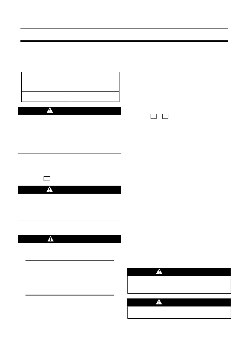
It is required that the water chamber of the
pump casing is sufficiently primed with water
before operating the pump.
- PLUG (PRIMING)
WARNING
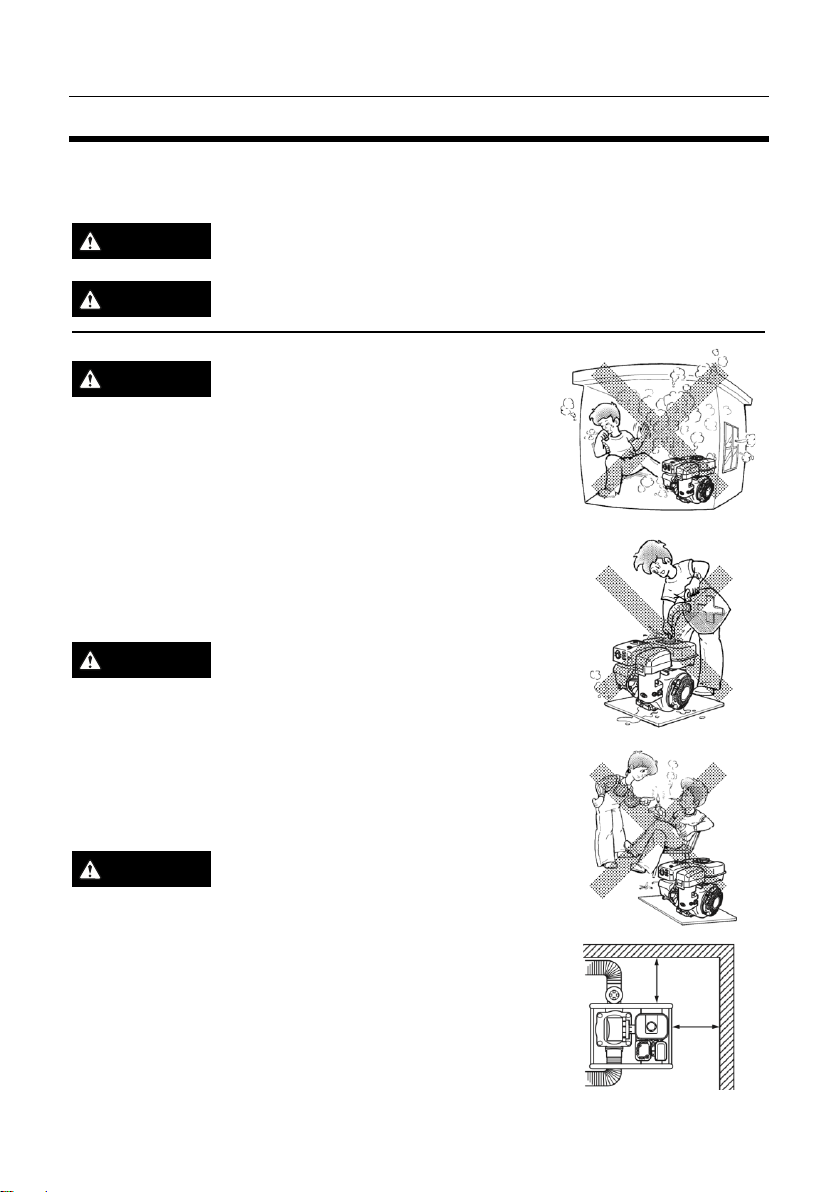
■ Never attempt to operate the pump
without priming water or the pump will
overheat.
■ Extended dry operation will destroy the
mechanical seal.
■ If the unit has been operated dry, stop
the engine immediately and allow the
pump to cool before adding priming water.
3. CHECK AIR CLEANER
(See Fig. 6 )
Check the air cleaner condition.
If oil is lacking or contaminated, add engine
oil up to the required oil level, or exchange it
with fresh engine oil.
5. ORERATING YOUR PUMP
1. STARTING
a) Open the fuel valve. (See Fig. 4 -A)
- OPEN
b) Set the speed control lever to the START
position. (See Fig. 5 -B)
c) Pull the starter handle slowly until
passing the compression point
(resistance will be felt), then return the
handle to its original position.
d) Lift down decompression lever.
(See Fig. 7 -A)
- Down
e) Pull briskly. Do not pull out the rope
completely.
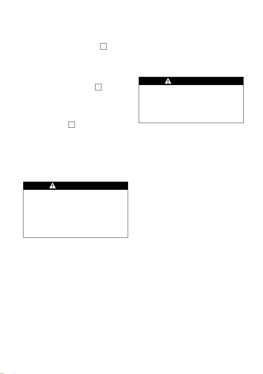
CAUTION
■ Be sure to pull the recoil starter handle
forcibly.
■ Do not pull out the rope completely.
d) After the engine starts, allow the starter
handle to return to its original position
while still holding the handle.
e) Warm up the engine without a load for a
2 or 3 minute.
2. RUNNING
After the engine starts, set the speed control
lever close to “STOP” position (IDLE position)
and warm it up without a load for a few
minutes. (See Fig. 5 -B)
- IDLE
Gradually move the speed control lever
toward “START” position and set it to the
required engine speed.
- START
NOTE
Whenever high-speed operation is not
required, slow the engine down (idle), by
moving the speed control lever, to save fuel
and extend engine life.
3. STOPPING
a) Set the speed control lever close to
“STOP” position (IDLE position) and allow
the engine to run at low speed for 2 or 3
minutes before stopping. (See Fig. 5 -B)