DAKOTA ULTRASONICS MiniMax v2.0 User manual

OPERATION MANUAL
DAKOTA ULTRASONICS
MiniMax v2.0
Ultrasonic Bolt Tension Monitor
P/N P-156-0005 Rev 3.00, June 2019


Table of Contents
CHAPTER ONE INTRODUCTION ..................................................................... 1
1.1 GENERAL DISCLAIMER .......................................................................................................... 1
1.2 SAFETY ................................................................................................................................ 1
1.3 WARRANTY .......................................................................................................................... 2
CHAPTER TWO ABOUT THIS MANUAL ......................................................... 3
2.1 NEW TO ULTRASONICS? ....................................................................................................... 3
2.2 NEW TO FASTENER MEASUREMENT? ..................................................................................... 3
2.3 MINIMAX OVERVIEW ............................................................................................................. 3
2.4 TABBED & HOT MENU REFERENCE ....................................................................................... 6
CHAPTER THREE QUICK START GUIDE ....................................................... 8
3.1 OVERVIEW ........................................................................................................................... 8
3.2 GETTING THE MINIMAX READY .............................................................................................. 8
3.3 SETTING UP THE MINIMAX .................................................................................................... 8
3.4 CREATING A NEW GROUP TO STORE MEASUREMENTS ........................................................ 11
3.5 SETTING THE APPROXIMATE LENGTH .................................................................................. 19
3.6 MEASURING REFERENCE LENGTHS ..................................................................................... 22
3.7 MEASURING ELONGATIONS ................................................................................................. 23
CHAPTER FOUR KEYBOARD, MENU, & CONNECTOR REFERENCE ....... 25
4.1 MENU KEY (OPERATION & SUB MENUS) .............................................................................. 25
4.2 CAL – MENU ...................................................................................................................... 27
4.3 MATL (MATERIAL) – MENU ................................................................................................. 28
4.4 GEOM (GEOMETRY) – MENU ............................................................................................. 28
4.5 DISP (DISPLAY) – MENU .................................................................................................... 29
4.6 TUNE – MENU .................................................................................................................. 30
4.7 GATES – MENU ................................................................................................................ 31
4.8 AUTO – MENU .................................................................................................................. 31
4.9 SETUP – MENU ................................................................................................................ 32
4.10 DATA – MENU ................................................................................................................ 32
4.11 UTIL (UTILITIES) – MENU ................................................................................................. 33
4.12 XFER (TRANSFER) – MENU ............................................................................................. 34
4.13 CLR (CLEAR) KEY ............................................................................................................ 34
4.14 MEAS (MEASUREMENT MODE) KEY .................................................................................. 34
4.15 OK KEY ........................................................................................................................... 34
4.16 ESC KEY ..................................................................................................................... 35
4.17 ARROW KEYS ................................................................................................................... 35

4.18 ENTER KEY .................................................................................................................... 35
4.19 AUTO SET KEY ............................................................................................................. 35
4.20 ON/OFF KEY .................................................................................................................. 35
4.21 NAVIGATING THE HOT MENU ............................................................................................ 35
4.22 TOP & BOTTOM END CAPS ............................................................................................... 37
CHAPTER FIVE THEORY OF OPERATION .................................................... 38
5.1 ULTRASONIC MEASUREMENT OF BOLTS .............................................................................. 38
5.2 FEATURES OF THE MINIMAX ............................................................................................... 38
5.3 ULTRASONIC WAVES .......................................................................................................... 39
5.4 MEASUREMENT MODE ........................................................................................................ 39
CHAPTER SIX BOLT PREPARATION ............................................................ 40
6.1 USE OF ULTRASONIC COUPLANT ........................................................................................ 40
6.2 TRANSDUCER CONTACT REQUIREMENTS ............................................................................ 40
6.3 BOLT END REFLECTORS ..................................................................................................... 42
CHAPTER SEVEN TRANSDUCER SELECTION ............................................ 44
7.1 SELECTING THE TRANSDUCER ............................................................................................ 44
CHAPTER EIGHT MEASURING SYSTEM ZERO (CALIBRATION) ............... 45
8.1 INTRODUCTION .................................................................................................................. 45
8.2 CALIBRATION / ZERO MISNOMER ......................................................................................... 45
8.3 CREATING A GROUP TO DOCUMENT ZERO (CALIBRATION) DATA .......................................... 46
8.4 AUTO ZERO/CALIBRATION .................................................................................................. 54
8.5 USING A STANDARD BOLT .................................................................................................. 60
8.6 CALIBRATION / ZERO BARS & TRIPLE SIDED GLASS BLOCK ................................................. 74
CHAPTER NINE TEMPERATURE COMPENSATION ..................................... 91
9.1 PURPOSE .......................................................................................................................... 91
9.2 MANUAL MODE .................................................................................................................. 91
9.3 SEMI AUTOMATIC MODE ..................................................................................................... 92
9.4 AUTOMATIC MODE ............................................................................................................. 94
CHAPTER TEN BOLT MATERIAL CALIBRATION ......................................... 95
10.1 WHY CALIBRATE? ............................................................................................................ 95
10.2 VELOCITY CALIBRATION ................................................................................................... 95
10.3 STRESS FACTOR CALIBRATION .......................................................................................... 99
10.4 TEMPERATURE FACTOR CALIBRATION ............................................................................ 103
CHAPTER ELEVEN LOAD MEASURMENT .................................................. 106
11.1 CALCULATING LOAD FACTOR .......................................................................................... 106
11.2 CALIBRATING LOAD FACTOR (FIELD CALIBRATION) .......................................................... 108

11.3 PERFORMING A FIELD CALIBRATION ................................................................................ 109
CHAPTER TWELVE MEASUREMENT & WAVEFORM DISPLAY ............... 123
12.1 QUANTITIES OF MEASUREMENT ...................................................................................... 123
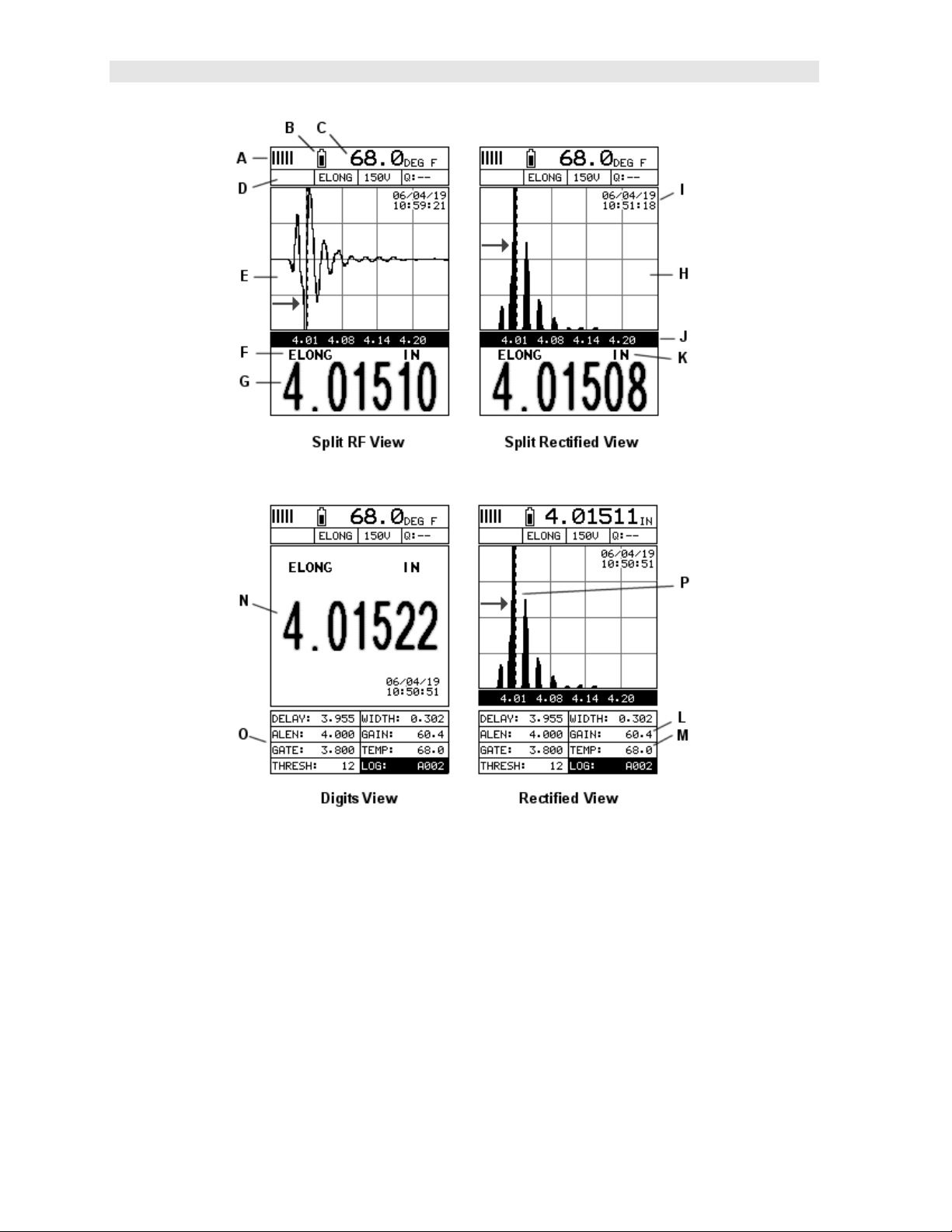
12.2 DISPLAY VIEW OPTIONS ................................................................................................. 124
12.3 ADJUSTING THE DISPLAY ................................................................................................ 128
12.4 GAIN .............................................................................................................................. 132
12.5 GATE ............................................................................................................................. 135
12.6 THRESHOLD ................................................................................................................... 138
12.7 INTERPRETING THE WAVEFORM ...................................................................................... 141
12.8 MANUALLY LOCATING THE ECHO .................................................................................... 142
12.9 AUTOMATIC ECHO OPTIMIZATION (AUTO SET) ................................................................. 144
12.10 UNLOADED LENGTH AND ELONGATION MEASUREMENTS ................................................ 147
CHAPTER THIRTEEN ADDITIONAL FEATURES ........................................ 148
13.1 QUALITY/CORRELATION (TRANSDUCER PLACEMENT) ...................................................... 148
13.2 CONTRAST ..................................................................................................................... 148
13.3 BACKLIGHT .................................................................................................................... 149
13.4 GRAPHICS OPTIONS (LOOK & FEEL) ................................................................................ 150
13.5 PULSE ........................................................................................................................... 152
13.6 PULSER VOLTAGE .......................................................................................................... 153
13.7 DAMPING ....................................................................................................................... 154
13.8 DIGITIZER ...................................................................................................................... 155
13.9 POLARITY ...................................................................................................................... 156
13.10 ALARM MODE ............................................................................................................... 157
13.11 KEY CLICK ................................................................................................................... 160
13.12 DATE & TIME ................................................................................................................ 160
13.13 UPGRADE GAUGE ........................................................................................................ 162
13.14 FREEZE & CAPTURE ..................................................................................................... 163
CHAPTER FOURTEEN DATA STORAGE – SETUP, EDIT, & VIEW FILES 165
14.1 INTRODUCTION TO GROUP (SPREADSHEET) FORMAT ....................................................... 165
14.2 CREATING A NEW GROUP ............................................................................................... 165
14.3 STORING A READING ....................................................................................................... 168
14.4 VIEWING STORED READINGS ........................................................................................... 169
14.5 DELETING GROUPS (FILES) ............................................................................................ 170
14.6 EDITING A GROUP (FILE) ................................................................................................ 173
14.7 CHANGING THE ACTIVE FILE - OPEN ................................................................................ 175
14.8 CLOSING AN ACTIVE FILE - CLOSE ................................................................................... 177
CHAPTER FIFTEEN SETUPS – CREATE, STORE, EDIT, & RECALL ....... 178
15.1 INTRODUCTION TO SETUPS ............................................................................................. 178

15.2 OPENING A SETUP ......................................................................................................... 178
15.3 SAVING A SETUP ............................................................................................................ 179
15.4 DELETING A SAVED SETUP ............................................................................................. 182
15.5 USING THE DEFAULT SETUP ........................................................................................... 184
15.6 SELECTING A LANGUAGE ................................................................................................ 185
CHAPTER SIXTEEN SOFTWARE, FILE TRANSFER, & UPGRADES ......... 187
16.1 COMPUTER SYSTEM REQUIREMENTS .............................................................................. 187
16.2 INSTALLING DAKVIEW ..................................................................................................... 187
16.3 COMMUNICATING WITH MINIMAX .................................................................................... 187
16.4 LINE POWER .................................................................................................................. 187
16.5 UPGRADING THE MINIMAX .............................................................................................. 187

1
CHAPTER ONE
INTRODUCTION
The Dakota Ultrasonics model MiniMax is used to measure the stretch (elongation,
load, stress and %strain) of a fastener under tension. This is accomplished
ultrasonically by sending an ultrasonic wave down the length of the fastener and
accurately measuring the change in transit time between an unloaded versus loaded
fastener/bolt, and calculating a physical stretch. The objective for using ultrasonics,
over conventional/mechanical methods is accuracy. Most conventional methods
refer to a torque value which has limited accuracy due to the coefficient of friction.
The coefficient of friction is difficult to determine, as it depends on the control and
application of lubrication.
The MiniMax avoids the coefficient of friction entirely, using the transit time of a
wave, Hooke’s law, and Young’s modulus to accurately calculate the stretch on a
bolt. Since the MiniMax cannot physically stretch a bolt, both
conventional/mechanical methods and the MiniMax are complimentary and used in
conjunction.
Dakota Ultrasonics maintains a customer support resource in order to assist users
with questions or difficulties not covered in this manual. Customer support may be
reached at any of the following:
Dakota Ultrasonics Corporation
1500 Green Hills Road, #107
Scotts Valley, CA 95066 USA
Telephone: (831) 431-9722
Facsimile: (831) 431-9723
www.dakotaultrasonics.com
1.1 General Disclaimer
The manual should be read and understood prior to using the MiniMax. This
operating manual provides the user with all the general information necessary to use
and adjust the designed features. However, this manual is not a certified
NDT/Bolting training course, nor is it intended to be one. Training, according to
company requirements, is recommended. The responsibility for proper use of the
instrument rests solely on the user.
1.2 Safety
Using the MiniMax while standing in water or in a wet environment can result in
serious electric shock, injury, and even death.
Operating the MiniMax with damaged or inadequate cables and power source can
result in serious electric shock, injury, and even death.

2
Failure to read this manual and understand the proper operation of the MiniMax can
result in inaccurate measurements, and lead to decisions which cause property
damage, personal injury, or even death.
Use of the MiniMax for any other purpose, or in any other manner than described in
this manual invalidates the warranty and can result in serious electric shock, injury,
and even death.
1.3 Warranty
The Dakota Ultrasonics MiniMax carries a two year limited warranty. The warranty
only applies to MiniMax units being operated as described in this manual. Software
and hardware failures of the unit will be repaired or replaced at Dakota Ultrasonics
discretion. Dakota Ultrasonics will not be held liable for any damage caused,
interruption of business, loss of profits, etc., resulting from such failures. Dakota
Ultrasonics will not be liable to repair or replace a unit, which has been damaged,
used inappropriately, or subject to unauthorized repair by the purchaser.

3
CHAPTER TWO
ABOUT THIS MANUAL
This chapter is intended to help you make the best use of this manual. Readers may
have different knowledge of ultrasonic bolt measurement and may find parts of this
manual repetitive or unnecessary.
2.1 New To Ultrasonics?
There are a variety of ultrasonic applications currently being utilized in today’s
industry. For example weld inspection, thickness measuring, immersion testing of
flaws, etc. The use of ultrasound to measure forces in fasteners is relatively new
compared to the previously mentioned traditional applications.
Ultrasonic measurement of bolts provides an extremely accurate means of
determining fastener load, provided the correct techniques are utilized. As a new
user, careful consideration of this entire manual is highly recommended.
2.2 New to fastener measurement?
Assuming you are familiar with ultrasonics, but unfamiliar with fastener measurement,
the chapters on transducer selection and the theory of operation can be skipped
entirely.
The MiniMax measures load on the fastener by measuring the amount the fastener
stretches. As load is applied to the fastener, it stretch’s just as a spring would
stretch. The stretch is proportional to the load while the load is less than the elastic
limit of bolt. By measuring the stretch of the fastener and knowing the physical
properties of the fastener, the load of the fastener can be calculated. The MiniMax
measures the fastener stretch by ultrasonically measuring the change in length.
Be sure to setup and experiment with a test fixture of some kind as a means of
becoming familiar with your MiniMax.
2.3 MiniMax Overview

Dakota Ultrasonics
4
In order to understand how to operate the MiniMax, it’s best to start off with an
understanding of what it is we’re looking at exactly. The MiniMax has a lot of great
features, tools, and flexibility to assist you with all of your bolting applications. Let’s
have a brief look at the screens you’ll be looking at most often:
A. Repeatability/Stability Indicator – Indicates the reliability of the measured
bolt length. When all the vertical bars are fully illuminated and the last digit on
the digital thickness value is stable, the MiniMax is reliably measuring the
same value on a consistent basis.
B. Battery Icon – Indicates the amount of battery life the MiniMax has
remaining.

MiniMax Bolt Tension Monitor
5
C. Temperature – Indicates the current temperature of either the temperature
sensor, or manual value entered.
D. Feature Status Bar – Indicates the features currently enabled and in use:
Alarm
Quantity
Pulser Voltage
Q-Factor (wave correlation)
E. RF A-Scan Display (split screen) – Displays the radio frequency sound wave
reflection returned the opposite end of the bolt being measured. The RF view
displays both the positive and negative cycles.
F. Quantity – Displays the current quantity setting used (elongation, load, stress,
strain or time).
G. Digital Measurement – Display in inches, millimeters, KSI, KIPS, %strain,
time (nanoseconds).
H. Rectified A-Scan Display – Displays either the positive or negative half cycle
wave reflection returned from the opposite end of the bolt being measured,
depending on the polarity selected.
I. Time & Date – Feature to display either the time, date, or both time and date
on the main measurement screen.
J. Length Division Markers – Measurement scale of length.
K. Units – Displays the current measurement units being used (English, Metric).
L. Gain – The current gain setting can be adjusted at any time while in
measurement mode.
M. Temperature – Refer to (C) above. The location of the temperature is
displayed in this location when the hot menus are shown. Notice in (C) the
view is split screen and temperature is displayed in the top right corner of the
display. When the temperature mode is set ‘manual’, the value can be
changed at any time.
N. Digital Measurement – Display in inches, millimeters, KSI, KIPS, %strain,
time (nanoseconds).
O. Hot Menu items – We call this menu section our “hot menu”, as these items
are the most commonly adjusted features, requiring quick access from the
user. They can be displayed and scrolled by pressing the key at any
time. The key advances forward and the key backwards to the next
hot menu item.
P. Detect/Gate/Threshold – The broken dotted line demonstrates where the
MiniMax is currently detecting on the waveform. Notice the horizontal line
with an arrow pointing at the detection point. This is the ‘gate’, and the height
of the line from the baseline is the ‘threshold’ level.

Dakota Ultrasonics
6
2.4 Tabbed & Hot Menu Reference
The following table is a quick menu reference guide of the tabbed menu items, which
can be accessed by pressing the key multiple times to tab right, or the key
multiple times to tab left through the tabbed menus. The MiniMax has 11 tabbed
menu titles and multiple submenu items as illustrated below. The MiniMax also has
1 ‘hot menu’ subset of commonly adjusted menu items. They can be quickly
accessed from the main measurement screen by pressing the key multiple
times to access and tab right, or pressing the key multiple times to tab left
through the hot menu cells. Refer to Chapter Four for additional definitions and
information on the keypad and menu items.
Hot Menu Items
Note: “Log” and “Temp” are also listed in the Hot Menu, and are used to access data storage if no log
file is currently open, or display log or grid file if open, as well as display the temperature.
Start >>
CAL MATL GEOM DISP TUNE GATES AUTO SETUP
ZERO MODE UNITS QUANTITY VIEW PULSE POLARITY AUTO SET OPEN
ZERO TYPE LOAD
FACTOR
CONTRAST PULSER
VOLTAGE
GATE APPROX LEN
(ALEN)
SAVE
MEASURE
ZERO
VELOCITY LOAD
OFFSET
BACKLIGHT DAMPING THRESHOLD
1
DELETE
LOAD CAL
MODE
STRESS
FACTOR
AREA DELAY GAIN DEFAULT
SETUP
LOAD CAL
CALC
TEMP COEF EFFECTIVE
LEN
WIDTH GAIN STEP
RECT WAVE DIGITIZER LANGUAGE
DETECT
MARK

MiniMax Bolt Tension Monitor
7
>> End
DATA UTILS XFER
NEW TEMP MODE UPGRADE
GAUGE
EDIT ALARM CAPTURE TO
FILE
OPEN ALARM LOW ABOUT
CLOSE ALARM HIGH
DELETE ONE
FILE
KEY CLICK
DELETE ALL
DATA
SET DATE
SHOW DATE
SUMMARY

8
CHAPTER THREE
QUICK START GUIDE
3.1 Overview
This section demonstrates the basic procedures for setting up and measuring bolts
using the MiniMax. More in depth explanations pertaining to the individual functions
and features can be found in the chapters that follow.
Here we go!
3.2 Getting the MiniMax ready
Making all the connections
In order to get the MiniMax ready for operation; the following connections must
be made:
1) Remove the MiniMax from the carrying case.
2) Connect the transducer cable to the transducer and plug it into the MiniMax.
3) If a temperature sensor is being used, connect the sensor to the MiniMax.
3.3 Setting up the MiniMax
Please Read: In this section the MiniMax will be setup in its simplest form.
Remember this is only a quick start guide to get the user up and measuring bolts.
Before we setup the gauge to measure basic elongation, the following assumptions
must be made: A preset material type will be used. The user will not be re-measuring
the fasteners at a later date to monitor relaxation of the joint over time. This
eliminates the need for an instrument zero/calibration. All these assumptions will be
answered and explained in detail in the chapters that follow.
Selecting Default Setup

MiniMax Bolt Tension Monitor
9
1) Press the key to power up the MiniMax.
2) Press the key once to activate the menu items tab. Press the key
multiple times to tab right and the key multiple times to tab left until the
SETUP menu is highlighted and displaying the submenu items.
3) Use the and arrow keys multiple times to scroll through the sub
menu items until DEFAULT SETUP is highlighted.
4) Press the key to display the confirmation screen, followed by pressing
the key to load the default setup.
Selecting the Units

Dakota Ultrasonics
10
Note: The default setup, selected in the previous section, automatically
defaults to English units – inches. Follow the procedure below to change the
units to Metric, if needed.
1) Press the key multiple times to tab right and the key multiple times
to tab left until the MATL menu is highlighted and displaying the submenu
items.
2) Use the and arrow keys to scroll through the sub menu items until
UNITS is highlighted.
3) Press the and arrow keys to scroll through the unit options IN
(inches), IN HR (inches hi resolution), MM (millimeters), and MM HR
(millimeters hi resolution).
Note: The high-resolution options display an additional digit of resolution to the
measurement. This mode is typically used when measuring very short bolts
with very little elongation.
Selecting the Material Type
This section allows the user the ability to select a material from a list of preset
material types. Keep in mind that we are measuring elongation only. If your
material is not in the list, select a similar material type. When measuring in

MiniMax Bolt Tension Monitor
11
elongation mode, the measurement consists of a difference equation only
(Loaded Length – Unloaded Length = Length). Therefore, it doesn’t matter if
the ultrasonic length is different from the actual physical length, because the
Length will be the same. Example: 2.0080” physical loaded length – 2.0000”
physical unloaded length = 0.0080” Length which is equivalent to 2.1080”
ultrasonic loaded length – 2.1000” ultrasonic unloaded length = 0.0080”
Length.
1) Press the and arrow keys multiple times to scroll through the sub
menu items until TYPE is highlighted.
2) Press the key to display the list material types.
3) Press the and arrow keys multiple times to scroll through the
material list until the appropriate type is highlighted.
4) Press the key to display the confirmation screen.
5) Press the key to select the type and return to the menu screen, or
to cancel selecting the material type.
3.4 Creating a New Group to Store Measurements
Now that the MiniMax is all setup, this section will explain how to get started
measuring unloaded initial lengths. In order to do this, we need to create a group
that contains bolts. A group can have up to 250 bolts, each bolt containing 1
reference length (L-REF), and up to 51 elongations. Keep in mind that the MiniMax
uses a group to store measurements and all gauge settings at the time of
measurement.
Creating a Group Name

Dakota Ultrasonics
12
1) Press the key once to activate the menu items tab. Press the key
multiple times to tab right, and the key multiple times to tab left, until the
DATA menu is highlighted and displaying the submenu items.
2) Press the and arrow keys multiple times to scroll through the sub
menu items until NEW is highlighted.
3) Press the key to display the New Group Edit Box.
4) Press the and arrow keys multiple times to scroll through the new
Group List Items until NAME is highlighted.
5) Press the key to activate the Alpha Edit Box.
6) Press the arrow keys to highlight the appropriate alpha
characters.
7) Press the key to select a character and advance to the next field of the
Group Name.

MiniMax Bolt Tension Monitor
13
8) Use the key to backspace if necessary.
9) Repeat steps 6 - 8 until the Group Name is completed.
10) Press the key to save the Group Name and return to the Group List
Items menu, or to cancel entering the Group Name.
Creating a Group Note
1) Press the and arrow keys multiple times to scroll through the new
Group List Items until NOTE is highlighted.
2) Press the key to activate the Alpha Edit Box.
3) Press the arrow keys to highlight the appropriate alpha
characters.

Dakota Ultrasonics
14
4) Press the key to select a character and advance to the next field of the
Group Note.
5) Use the key to backspace if necessary.
6) Repeat steps 3 - 5 until the Group Note is completed.
7) Press the key to save the Group Note and return to the Group List
Items menu, or to cancel entering the Group Note.
Selecting the Number of Bolts in the Group
Note: A group can contain up to 250 bolts. There must be at least 1 bolt in a
group.
1) Press the and arrow keys multiple times to scroll through the new
Group List Items until NUM BOLTS is highlighted.
2) Press the key to display the Digits Edit Box.
3) Press the and arrow keys multiple times to scroll the highlighted
value.
4) Press the and arrow keys multiple times to scroll the digit
locations.
Table of contents
Other DAKOTA ULTRASONICS Monitor manuals