Daktronics P1192 User manual

201 Daktronics Drive
Brookings, SD 57006-5128
www.daktronics.com/support
800.325.8766
OUTDOOR SCOREBOARD
HORNS
INSTALLATION MANUAL
P1192
DD3088739
Rev 03
12 March 2021

Copyright © 2015-2021
All rights reserved. While every precaution has been taken in the preparation of this manual, the publisher assumes no
responsibility for errors or omissions. No part of this book covered by the copyrights hereon may be reproduced or copied
in any form or by any means—graphic, electronic, or mechanical, including photocopying, taping, or information
storage and retrieval systems—without written permission of the publisher.
Daktronics trademarks are property of Daktronics, Inc. All other trademarks are property of their respective companies.

– i –
Table of Contents
1 12 VDC Horn Installation ������������������������������������������������������������������������������������������������������1
Equipment .............................................................................................................................................1
Location.................................................................................................................................................1
Horn Interface Card & Horn Plate Assembly.....................................................................................1
Horn Interface Card Installation������������������������������������������������������������������������������������������������������1
Horn Plate Assembly Installation�����������������������������������������������������������������������������������������������������2
Trumpet Horn Installation .....................................................................................................................2
Preparation����������������������������������������������������������������������������������������������������������������������������������������2
Installation�����������������������������������������������������������������������������������������������������������������������������������������2
TI-2003 12 VDC Horn .............................................................................................................................3
Compact Horn Replacement.............................................................................................................3
Schematics............................................................................................................................................3
2 120 VAC Trumpet Horn Installation �������������������������������������������������������������������������������������4
Equipment .............................................................................................................................................4
Location.................................................................................................................................................4
Basic Horn Installation ..........................................................................................................................4
Complete Horn Installation..................................................................................................................4
Horn Interface Card Installation������������������������������������������������������������������������������������������������������4
Horn Installation��������������������������������������������������������������������������������������������������������������������������������5
Schematics............................................................................................................................................5
3 24 VDC Trumpet Horn Installation (Solar Power Option Only)������������������������������������������6
Equipment .............................................................................................................................................6
Location.................................................................................................................................................6
Horn Preparation ..................................................................................................................................6
Horn Installation ....................................................................................................................................6
A Reference Drawings �������������������������������������������������������������������������������������������������������������9

This page intentionally left blank.

12 VDC Horn Installation
1
1 12 VDC Horn Installation
Reference Drawings:
Wiring Guide; Gyrus Outdoor Horn Kits .......................................................... DWG-3068821
Refer to DWG-3068821 in Appendix A for general wiring details of LED scoreboard horns.
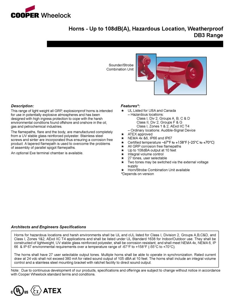
The following section describes the 12 VDC trumpet horn installation and compact horn
replacement for an LED scoreboard. Assemblies are available for both 120 and 240 VAC
scoreboards.
Note: Disconnect power to the scoreboard before installing the horn!
Equipment
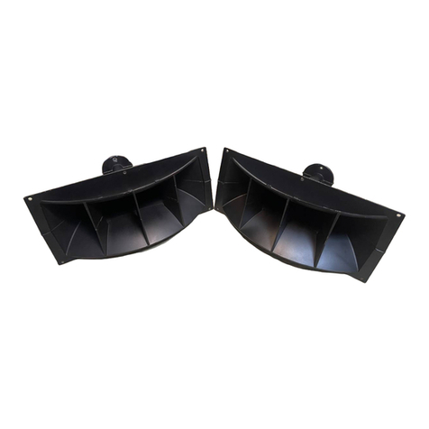
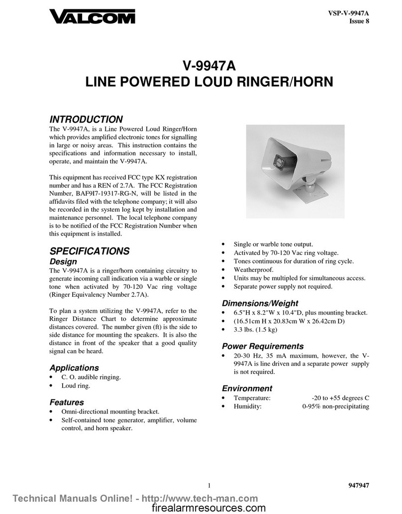
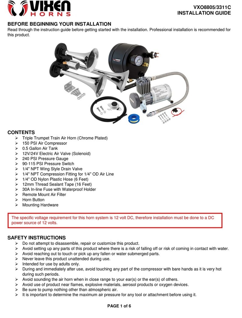
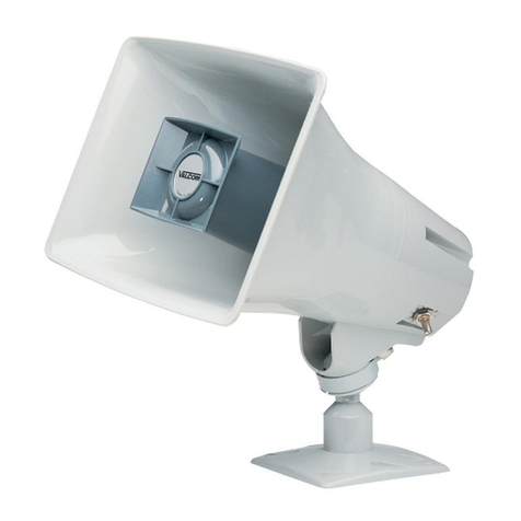
The trumpet horn kit consists of:
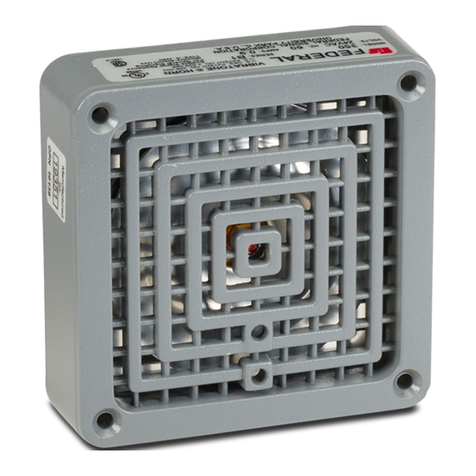
• a horn
• a metal mounting angle (trumpet horn only)
• a metal enclosure and 12 volt power plate assembly
• a horn interface card and harness
• assorted #10 screws, tapping screws, and nuts
Location
The horn entrance panel is typically located in the center of the lower half of the
scoreboard (refer to the component location drawings included in the scoreboard
manual for specic location). The horn will be mounted directly to this entrance panel.
The panel may be secured only by screws, or it may have hinges to swing open.
Horn Interface Card & Horn Plate Assembly
• If the horn kit was ordered with the scoreboard, the horn interface card and horn
plate assembly were likely installed at the factory; skip ahead to Trumpet Horn
Installation (p�2).
• If these components have not been installed, follow the instructions under Horn
Interface Card Installation (p�1) and Horn Plate Assembly Installation (p�2).
Horn Interface Card Installation
Reference Drawings:
Horn Card Installation; Gyrus Driver................................................................ DWG-3067686
• Current 120 VAC horn card part number: 0P-1192-0399
• Current 240 VAC horn card part number: 0P-1150-0255
Attach the horn interface card inside the scoreboard driver enclosure and make the
proper wiring connections from the horn interface card to the driver per DWG-3067686.

12 VDC Horn Installation
2
Horn Plate Assembly Installation
Reference Drawings:
Plate Assy: Outdoor SCBD 12VDC Horn- AS5K ................................................ DWG-128944
DWG-128944 shows the components of the horn plate assembly.
1� Open the horn entrance panel as described in Location (p�1).
2� On the interior of the back panel of scoreboard, drill two 5/32" holes 4" apart (these
holes may have been pre-drilled at the factory). The enclosure is to be attached to
the inside of the scoreboard and accessible when the entrance panel is opened.
Note: Be careful not to damage any internal components when drilling!
3� Attach the enclosure to the scoreboard using the #10 tapping screws provided.
4� Attach the plate assembly to the enclosure using #10 tapping screws provided.
5� Attach the cover to the enclosure using the #10 tapping screws provided.
Trumpet Horn Installation
Preparation
Reference Drawings:
Horn Assembly..................................................................................................... DWG-320004
1� Insert bushings into the appropriate 3/8" holes in the mounting angle.
2� Thread the two gray wires from the horn through the top of the mounting angle.
3� Attach the horn to the mounting angle using the #10 hardware provided.
4� Thread the two gray wires through the 3/8" hole in the rear of the mounting angle.
Installation
Reference Drawings:
Template, Hole Drilling, Trumpet Horn................................................................ DWG-83502
F.Assy: 12V DC Horn Mounting- Outdoor LED SCBD ..................................... DWG-3067687
1� Locate the horn entrance panel as described in Location (p�1). Remove the 2"
knockout on this panel. If a knockout has not been provided, use DWG-83502 as a
guide to drill one 3/8" hole and two 7/32" holes in the panel.
Note: Be careful not to damage any internal components when drilling!
2� Thread the two gray wires from the horn through the knockout (or 3/8" hole) in the
scoreboard access panel.
3� Place horn/angle bracket assembly over the 2" knockout and 7/32" holes in the front
panel of the scoreboard and attach using #10 hardware provided.
4� Using the wiring nuts provided, connect one gray wire from the horn to the black wire
from the plate assembly. Connect the other gray wire to the red wire.
5� Route the 2-pin horn plate plug labeled P3 to jack J3 on the horn interface card, per
DWG-3067687. If the harness does not reach, connect the 2-pin to 2-pin extension
cable between the horn plate and the horn interface card as needed.
6� Close and secure the horn entrance panel.
7� To test the horn, power on the scoreboard and control console, and press HORN.

12 VDC Horn Installation
3
TI-2003 12 VDC Horn
Reference Drawings:
Harness: TI-2003, TI-2010, TI-2015 Horn Signal Cable........................................ DWG-316634
Horn; 12VDC Trumpet, 120V Input, TI-2003 .................................................... DWG-3026331
Horn Card Installation; Gyrus Driver................................................................ DWG-3067686
Refer to DWG-3067686 for horn card installation. One main difference from the standard
horn card installation, as illustrated in DWG-316634, is the 4-pin to 9-pin cable that
connects from J2 on the horn card to digit jack J5 on the driver. This is to allow the horn
to sound Shot/Stall Time =0 or Delay of Game =0.
Refer to DWG-3026331 for instructions to mount a 12VDC trumpet horn to the TI-2003.
Compact Horn Replacement
Reference Drawings:
Assy; 12V DC Compact Horn, 120V or 240V, Gyrus Driver........................... DWG-3054721
The compact horn is standard on certain scoreboards. Therefore, this section discusses
the replacement of an existing horn.
1� Locate the horn entrance panel as described in Location (p�1) and open it.
2� Unscrew the wiring nuts that connect the existing horn to the plate assembly.
3� Remove the #10 hardware securing the existing horn.
4� Cut the two-pin plug off the new horn and strip 5/32" of insulation from each wire.
Note: Remember what wire was connected to which pin of the plug!
5� Using the wiring nuts provided, connect the Pin 2 wire from the horn to the black wire
from the plate assembly. Connect the Pin 1 wire to the red wire.
6� Attach the new horn to the bracket using the #10 hardware.
7� Make wiring connections between the horn interface card, the horn plate assembly,
and the existing scoreboard driver per DWG-3054721.
8� Close and secure the horn entrance panel.
9� To test the horn, power on the scoreboard and control console, and press HORN.
Schematics
Reference Drawings:
Schematic- Outdoor SCBD 12VDC Trumpet Horn- AS5K ............................... DWG-128938
Schematic- Outdoor SCBD 12VDC Compact Horn ....................................... DWG-198618
240V Horn Conversation Kit, for 12V Trumpet Assy. ........................................ DWG-270554
Schematic, 240V OD SCBD 12VDC Trumpet Horn, AS5K ............................... DWG-325028
Refer to the appropriate drawing above for detailed horn plate wiring schematics.

120 VAC Trumpet Horn Installation
4
2 120 VAC Trumpet Horn Installation
Reference Drawings:
Wiring Guide; Gyrus Outdoor Horn Kits .......................................................... DWG-3068821
Refer to DWG-3068821 in Appendix A for general wiring details of LED scoreboard horns.
The following section describes the 120 VAC trumpet horn installation for an LED
scoreboard. Assemblies are only available for 120 VAC scoreboards.
Note: Disconnect power to the scoreboard before installing the horn!
Equipment
The trumpet horn kit consists of:
• a horn
• a metal mounting angle
• a horn interface card and harness
• assorted #10 screws, tapping screws, and nuts
Location
The horn entrance panel is typically located in the center of the lower half of the
scoreboard (refer to the component location drawings included in the scoreboard
manual for specic location). The horn will be mounted directly to this entrance panel.
The panel may be secured only by screws, or it may have hinges to swing open.
Basic Horn Installation
• If the horn kit was ordered with the scoreboard, the horn interface card, mounting
angle, and horn body were likely installed at the factory; follow the simple instructions
below.
a� Locate the horn entrance panel as described in Location (p�4).
b� Locate and screw the trumpet part of the horn into the horn body through the 2"
knockout on this panel.
• If these components have not been installed, skip ahead to Complete Horn
Installation (p�4).
Complete Horn Installation
Horn Interface Card Installation
Reference Drawings:
Horn Card Installation; Gyrus Driver................................................................ DWG-3067686
• Current 120 VAC horn card part number: 0P-1192-0399
Attach the horn interface card inside the scoreboard driver enclosure and make the
proper wiring connections from the horn interface card to the driver per DWG-3067686.

120 VAC Trumpet Horn Installation
5
Horn Installation
Reference Drawings:
Template, Hole Drilling, Trumpet Horn................................................................ DWG-83502
120V AC Horn Mounting, Outdoor Sports...................................................... DWG-1055044
Horn Mtg Instructions; 120V, TI-2003, Gyrus Driver......................................... DWG-3054691
Horn Card Installation; Gyrus Driver................................................................ DWG-3067686
1� Locate the horn entrance panel as described in Location (p�4). Remove the 2"
knockout on this panel. If the knockout has not been provided, use DWG-83502 as a
guide to drill one 2" hole in the panel.
Note: Be careful not to damage any internal components when drilling!
2� Remove the trumpet from the horn body by unscrewing it.
3� Mount the bracket to the scoreboard frame using #10 hardware provided, and
connect the horn harness to the horn wires with included wire nuts. Refer to DWG-
1055044. For the TI-2003 only, refer instead to DWG-3054691.
When replacing a horn:
a� Use 1/4" bolts, nuts, and lock washers provided to attach the horn body to the
mounting bracket so that the horn is on the same side as the short ange (the
horn should be pointing downward).
b� Be sure to mount the horn to the bracket so that the wires are facing the bottom
of the cabinet to prevent water from running along them.
c� Attach the copper ground lug to the bottom-right corner of the mounting
bracket using the bolt and serrated washer and nut provided, and connect the
green wire from the horn to the ground lug (does not apply to the TI-2003).
4� Route the 2-pin horn plug labeled P3 to jack J3 on the horn interface card, per DWG-
3067686. If the harness does not reach, connect the 2-pin to 2-pin extension cable
between the horn and the horn interface card as needed.
5� Close the access panel and screw the trumpet back onto the horn body.
6� To test the horn, power on the scoreboard and control console, and press HORN.
Schematics
Reference Drawings:
Schematic: 120VAC Trumpet Horn................................................................... DWG-132173

24 VDC Trumpet Horn Installation (Solar Power Option Only)
6
3 24 VDC Trumpet Horn Installation (Solar Power
Option Only)
The following section describes the 24 VDC trumpet horn installation for a solar-powered
LED scoreboard.
Note: Disconnect power to the scoreboard before installing the horn!
Equipment
The trumpet horn kit consists of:
• a horn
• a metal mounting angle
• a 24 volt outdoor horn harness
• assorted #10 screws, tapping screws, and nuts
Location
The horn entrance panel is typically located in the center of the lower half of the
scoreboard (refer to the component location drawings included in the scoreboard
manual for specic location). The horn will be mounted directly to this entrance panel.
The panel may be secured only by screws, or it may have hinges to swing open.
Horn Preparation
Reference Drawings:
Horn Assembly..................................................................................................... DWG-320004
1� Insert bushings into the appropriate 3/8" holes in the mounting angle.
2� Thread the two wires from the horn through the top of the mounting angle.
3� Attach the horn to the mounting angle using the #10 hardware provided.
4� Thread the two wires through the 3/8" hole in the rear of the mounting angle.
Horn Installation
Reference Drawings:
Template, Hole Drilling, Trumpet Horn................................................................ DWG-83502
Installation Diagram: Solar Power Scoreboard ............................................... DWG-315892
Assembly Horn Kit Option .................................................................................. DWG-321327
1� Locate the horn entrance panel as described in Location (p�6). Remove the 2"
knockout on this panel. If the knockout has not been provided, use DWG-83502 as a
guide to drill one 3/8" hole and two 7/32" holes in the panel.
Note: Be careful not to damage any internal components when drilling!
2� Thread the two wires from the horn through the knockout (or 3/8" hole) in the
scoreboard access panel.
3� Place horn/angle bracket assembly over the knockout/hole and 7/32" holes in the
front panel of the scoreboard and attach using #10 hardware provided.
4� Install the horn harness as shown in DWG-321327.

24 VDC Trumpet Horn Installation (Solar Power Option Only)
7
5� Make wiring connections between the horn and the existing scoreboard driver per
DWG-315892, Electrical Installation Details.
6� Close and secure the horn entrance panel.
7� To test the horn, power on the scoreboard and control console, and press HORN.

This page intentionally left blank.

Reference Drawings
9
A Reference Drawings
Any contract-specic drawings take precedence over these general drawings.
Reference Drawings:
Template, Hole Drilling, Trumpet Horn................................................................ DWG-83502
Schematic- Outdoor SCBD 12VDC Trumpet Horn- AS5K ............................... DWG-128938
Plate Assy: Outdoor SCBD 12VDC Horn- AS5K ................................................ DWG-128944
Schematic: 120VAC Trumpet Horn................................................................... DWG-132173
Schematic- Outdoor SCBD 12VDC Compact Horn ....................................... DWG-198618
240V Horn Conversation Kit, for 12V Trumpet Assy. ........................................ DWG-270554
Installation Diagram: Solar Power Scoreboard ............................................... DWG-315892
Harness: TI-2003, TI-2010, TI-2015 Horn Signal Cable........................................ DWG-316634
Horn Assembly..................................................................................................... DWG-320004
Assembly Horn Kit Option .................................................................................. DWG-321327
Schematic, 240V OD SCBD 12VDC Trumpet Horn, AS5K ............................... DWG-325028
120V AC Horn Mounting, Outdoor Sports...................................................... DWG-1055044
Horn; 12VDC Trumpet, 120V Input, TI-2003 .................................................... DWG-3026331
Horn Mtg Instructions; 120V, TI-2003, Gyrus Driver......................................... DWG-3054691
Assy; 12V DC Compact Horn, 120V or 240V, Gyrus Driver........................... DWG-3054721
Horn Card Installation; Gyrus Driver................................................................ DWG-3067686
F.Assy: 12V DC Horn Mounting- Outdoor LED SCBD ..................................... DWG-3067687
Wiring Guide; Gyrus Outdoor Horn Kits .......................................................... DWG-3068821

This page intentionally left blank.


THE CONCEPTS EXPRESSED AND DETAILS SHOWN ON THIS DRAWING
ARE CONFIDENTIAL AND PROPRIETARY. DO NOT REPRODUCE BY
ANY MEANS WITHOUT THE EXPRESS WRITTEN CONSENT OF
DAKTRONICS, INC. OR ITS WHOLLY OWNED SUBSIDIARIES.
COPYRIGHT 2017 DAKTRONICS, INC. (USA)
THIRD ANGLE PROJECTION
AH
REV
TITLE:
PROJECT:
INCHES [MILLIMETERS]
DESIGN:
SCALE:
DIM UNITS:DATE: SHEET
DO NOT SCALE DRAWING
FUNC - TYPE - SIZE
DRAWN: -
JOB NO.
-
STANDARD SCOREBOARDS
SCHEMATIC- OUTDOOR SCBD 12VDC TRUMPET HORN- AS5K
JCM
06MAR00
P1091 R 03 A
NONE
128938
081 OF 1
REV DATE: BY:
05 13 APR 07 DKD
REMOVED OUTDOOR LED DRIVE FROM SCHEMATIC
REMOVEDWIRE FROM J17
REV DATE: BY:
06 08 OCT 12 JML
ADDED WIRE COLOR FROM TRANSFORMER TO CR1
PER EC-7744
REV DATE: BY:
07 27 MAR 17 BTA
SWITCHED TRANSFORMER TERMINAL 10 AND 6
PER EC-23483
REV DATE: BY:
08 13 SEP 19 KDM
PER CN-88357 REPLACED E-1084 W/ E-1184

PPaarrtt##--DDWWGG--0000112288994444VVeerrssiioonn--0088..22DDeessccrriippttiioonn--NNAAPPLLAATTEEAASSSSYY;;OOUUTTDDOOOORRSSCCBBDD1122VVDDCCHHOORRNN,,AASS55KKLLiiffeeccyycclleeSSttaattee--FFuullllPPrroodduuccttiioonnLLaassttMMo