Klenn Air Horns JL-JK-OBA User manual

JL-JK-OBA
Installation and Operation Manual
Go to Table of Contents PG 3/35 REV: A (1/21/2019)
Table of Contents
1. LIST OF FIGURES .................................................................................................................................................5
2. How to Use this Manual .....................................................................................................................................6
2.1. Interactive Manual using Adobe Reader....................................................................................................6
2.2. Your Kit SKU Number and this Manual.......................................................................................................6
2.3. Illustration/Photo Details and Orientation.................................................................................................6
3. Safety First..........................................................................................................................................................7
4. Application Chart................................................................................................................................................8
4.1. 100% Direct Bolt-On Vehicle List................................................................................................................8
4.2. **Excluded Vehicles ...................................................................................................................................8
4.3. Aftermarket Product Compatibility............................................................................................................8
5. Installation Overview..........................................................................................................................................9
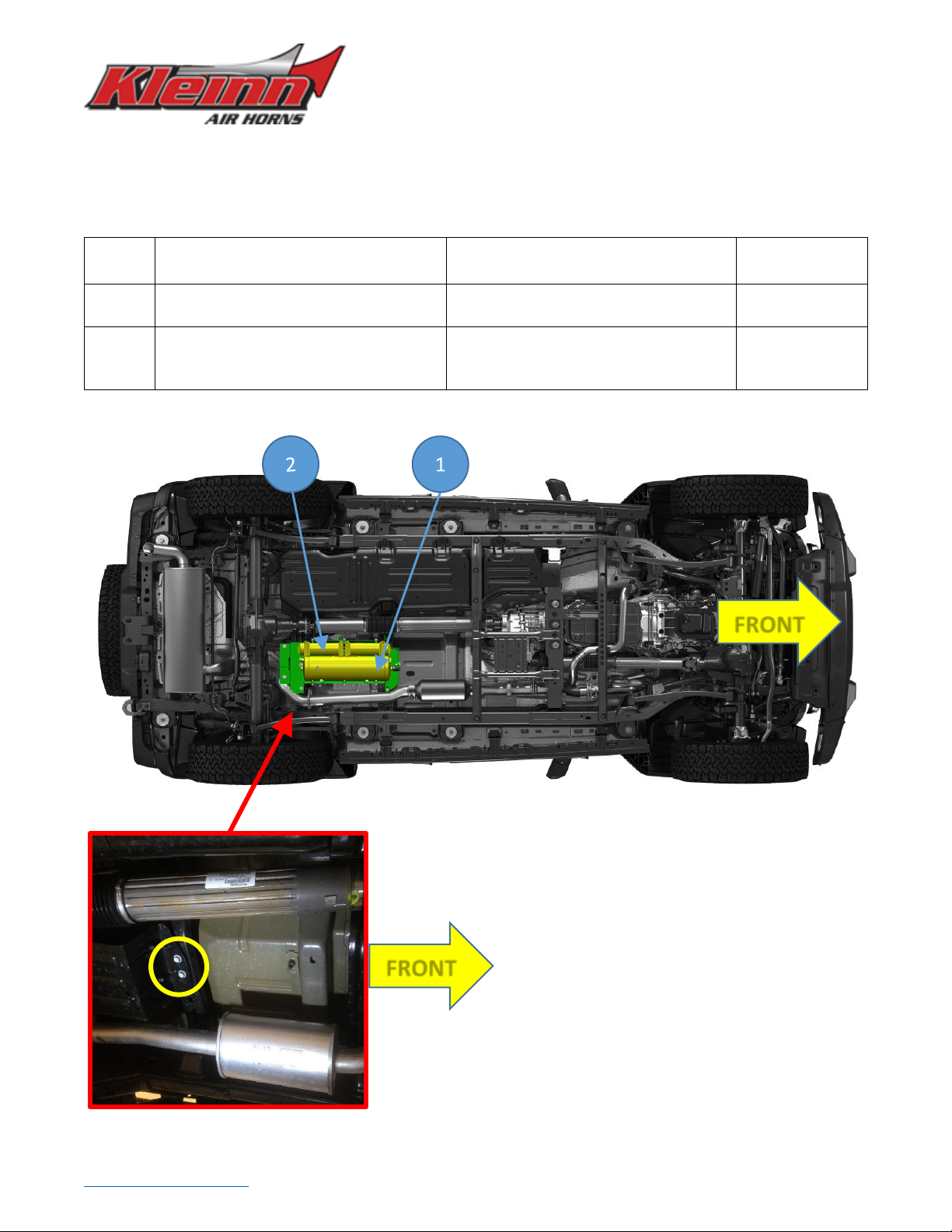
5.1. Kit Layout and System Location(s)..............................................................................................................9
5.2. Approximate Installation Time................................................................................................................ 10
5.3. ***Quick Install Outline........................................................................................................................... 10
6. List of Tools and Supplies ................................................................................................................................ 11
6.1. Standard Tool List (Required).................................................................................................................. 11
6.2. Special Tool List (Recommended) ........................................................................................................... 11
6.3. Shop Consumables List (Recommended)................................................................................................ 11
7. Parts List .......................................................................................................................................................... 12
7.1. Parts List covers following SKU Numbers................................................................................................ 12
7.2. Pre-Packaged Electro-Mechanical Items................................................................................................. 12
7.3. Air Fittings and Related Items ................................................................................................................. 13
7.4. Electrical Small Components and Related Items..................................................................................... 14
7.5. Bolt-On Mounting Brackets & Special Hardware .................................................................................... 15
7.6. Hardware/Fasteners................................................................................................................................ 16
8. On-Vehicle Electrical Installation..................................................................................................................... 18
8.1. Relay and Fuse Diagram for Air Compressor and Air Tank Pressure Switch ........................................... 18
8.2. Suggested Wire Routing for Air Compressor and Air Tank Pressure Switch........................................... 19
8.3. Disconnect Vehicle Battery(s).................................................................................................................. 19
8.4. Connect Wiring to Relay(s) and Fuse(s), then Attach to Vehicle............................................................. 19
8.5. Route Wiring............................................................................................................................................ 20
9. Bench Assembly Steps..................................................................................................................................... 21

JL-JK-OBA
Installation and Operation Manual
Go to Table of Contents PG 4/35 REV: A (1/21/2019)
9.1. Air Tank Fittings....................................................................................................................................... 21
9.2. Attach Compressor(s) onto Skid Plate Bracket (JK-101).......................................................................... 22
9.3. Attach Air Tank Straps (JK-202) to Air Tank Bracket (JK-201) and Form Straps ...................................... 23
10. On-Vehicle Mechanical Assembly Steps.......................................................................................................... 25
10.1. JK ONLY - Air Tank Bracket (JK-201) to Frame Installation...................................................................... 25
10.2. JL ONLY - Adapter Bracket (JL-204) to Frame Installation....................................................................... 28
10.3. JL ONLY - Air Tank Bracket (JK-201) to Frame Installation ...................................................................... 29
10.4. Air Tank to Tank Bracket Installation....................................................................................................... 32
10.5. Skid Plate and Compressor Installation (JK-101)..................................................................................... 33
10.6. Connect Air Compressor Leader Hose to Air Tank .................................................................................. 33
10.7. Connect Remote Quick Connect Kit to Vehicle ....................................................................................... 33
11. Initial Testing of Kit.......................................................................................................................................... 34
11.1. Reconnect Vehicle Battery(s) .................................................................................................................. 34
11.2. Test Air Compressor ................................................................................................................................ 34
11.3. Test Quick Connect Coupler .................................................................................................................... 34
12. General Operation of Kit ................................................................................................................................. 34
12.1. Compressor Operation ............................................................................................................................ 34
13. Routine Maintenance...................................................................................................................................... 34
14. Warranty Information ..................................................................................................................................... 35

JL-JK-OBA
Installation and Operation Manual
Go to Table of Contents PG 5/35 REV: A (1/21/2019)
1. LIST OF FIGURES
Figure 1 - Suggested Ignition Relay Diagram for JL-JK-OBA; Air Horn Also Shown ................................................. 18
Figure 2 - Suggested Wire Routing for Air Compressor and Pressure Switch (JLU Shown) .................................... 19
Figure 3 - Compressor Mounted onto JK-101 **JK6450 Upgrade Shown .............................................................. 22
Figure 4 - Compressor Fasteners Orientation (Stack-Up)........................................................................................ 22
Figure 5 - Rubber Trim Attached to JK-201 (Bracket shown on bench) .................................................................. 23
Figure 6 - JK-202 Attached to JK-201....................................................................................................................... 23
Figure 7 - JK-202 Hand Formed/Bent around Air Tank ........................................................................................... 24
Figure 8 - JK-202 Air Tank Strap with Rubber Trim.................................................................................................. 24
Figure 9 - JK-201 to Evap Canister Install ................................................................................................................ 25
Figure 10 - JK-201 to JKU Mounting Points for Hardware....................................................................................... 26
Figure 11 - JK-201 & JK-203 Mounting Strap Install over Crossmember................................................................. 27
Figure 12 –JLU Rear Crossmember Mounting Locations........................................................................................ 28
Figure 13 - JL-204 Adapter Bracket Bolted in Place................................................................................................. 28
Figure 14 –JLU Middle Crossmember & Ground Strap Mounting Point ................................................................ 29
Figure 15 - JK-201 to JLU Mounting Points for Hardware ....................................................................................... 29
Figure 16 - JK-201 & JL-204 Hardware Attached..................................................................................................... 30
Figure 17 - JK-201 & JL-204 Section View with Hardware Stack Up........................................................................ 30
Figure 18 –Ground Strap Nut removed; JK-201 Tank Bracket shown in place....................................................... 31
Figure 19 - JK-201 Mounting Points......................................................................................................................... 31
Figure 20 - Air Tank Mounted to JK-201.................................................................................................................. 32
Figure 21 - JK-101 Mounted to Tank Bracket (Air Tank not shown) ....................................................................... 33
Figure 22 - Air Coupler Mounted To Bumper......................................................................................................... 33

JL-JK-OBA
Installation and Operation Manual
Go to Table of Contents PG 6/35 REV: A (1/21/2019)
2. How to Use this Manual
2.1. Interactive Manual using Adobe Reader
It is recommended to open this digital PDF using Adobe Reader ® to take advantage of following key
features:
•Hyperlinks (blue underlined text) allow access to additional content via internet; click/tap to activate
oIncludes Installation Figures and “Figure xx”
•Table of Contents page allows easily navigating this manual; click/tap any section line to go to it
•Bookmarks allow quickly navigating to any section; click/tap
•Zoom IN on pictures by pressing “CTRL and +” at same time on PC, or pinch in on smart devices
•Zoom OUT on pictures by pressing “CTRL and -”at same time on PC, or pinch out on smart devices
To install Adobe Reader ®
On PC, or Mac
•visit https://get.adobe.com/reader/otherversions/
On Android, iPhone/iPad, and Windows devices,
•visit https://acrobat.adobe.com/us/en/acrobat/mobile-app.html
2.2. Your Kit SKU Number and this Manual
This manual covers installation, testing, and operation of following SKU part numbers
2.2.1. JL-JK-OBA (i.e., On-Board Air System)
2.2.2. JK6450 (i.e., Dual Compressor Upgrade)
NOTE: Illustrations and pictures contained herein may represent only one kit part number.Where
critical differences exist between kits (i.e., different parts, orientation, mounting points, etc.), additional
text, or necessary graphics are provided to minimize confusion.
Parts list explicitly state kit differences with (BOLD TEXT) inside parenthesis, shown below part number.
2.3. Illustration/Photo Details and Orientation
This manual may use digitally created illustrations, and/or actual photos of example vehicle. These graphics may
not include exact items found on your vehicle (i.e., electrical wiring, fuel lines, body panels, etc.). Illustrations
typically will be missing details and are for clarity to show critical mounting locations and orientation on vehicle.
Throughout this manual yellow arrows with text reading “FRONT”, may be
present over illustrations and pictures. These arrows specify direction toward
front of vehicle and provide clarity to how illustration is viewed.
FRONT

JL-JK-OBA
Installation and Operation Manual
Go to Table of Contents PG 7/35 REV: A (1/21/2019)
3. Safety First
Read manual thoroughly before starting installation of this kit. Verify you have all parts listed and that you
clearly understand this installation procedure. Contact Kleinn technical support for any questions.
Installation of this kit requires moderate mechanical aptitude; seek professional help if you’re not competent
using hand tools in tight uncomfortable spaces, and around possibly rusted and sharp vehicle parts.
Before starting, obtain proper tools required to perform installation correctly, adequate lighting, eye protection,
hearing protection for operating train horns, and hand protection to guard against sharp edges and metal burrs,
which may be present on kit parts and vehicle parts.
Throughout this manual the following words may be used; be aware of their meaning and application.
CAUTION: means damage could occur to vehicle, or kit parts during, or after installation
WARNING: means injury could occur to you or others, including damage to vehicle, or kit parts
DANGER: means serious injury or death could occur to you or others during installation

JL-JK-OBA
Installation and Operation Manual
Go to Table of Contents PG 8/35 REV: A (1/21/2019)
4. Application Chart
4.1. 100% Direct Bolt-On Vehicle List
JL-JK-OBA is a 100% direct bolt-on aftermarket product for Jeep vehicles listed in below chart; every effort has
been made to verify correct fitment on these vehicles in their factory, non-modified conditions.
MODEL YR
MODEL
DRIVE
ENGINE
BODY
TRIM
2018-2019
JLU
ALL
3.6L**
4 DOOR
ALL**
2007-2018
JKU
ALL
3.6L
4 DOOR
ALL**
NOTE: All vehicles listed may require drilling holes for ground wires and installing switches, based on
preference of installed switch locations and wire grounding points.
4.2. **Excluded Vehicles
JL-JK-OBA is NOT compatible with following JEEP vehicles:
4.2.1. ALL 2-Door Jeep JL
4.2.2. ALL 2-Door Jeep JK
4.2.3. Jeep JLU with 3.0L Diesel
4.2.4. Jeep JLU with Hybrid
4.3. Aftermarket Product Compatibility
4.3.1. This kit has been designed and tested to be compatible with leading manufacturers of
aftermarket truck steps, such as Amp Research Power Steps ® and all OEM standard and optional
steps.
4.3.2. This kit has NOT been designed or tested for use with leading manufacturers of aftermarket
exhaust systems.
4.3.3. This kit has NOT been designed or tested for use with leading manufacturers of aftermarket
drivetrains, or suspension systems.

JL-JK-OBA
Installation and Operation Manual
Go to Table of Contents PG 9/35 REV: A (1/21/2019)
5. Installation Overview
5.1. Kit Layout and System Location(s)
JL-JK-OBA consists of following sub-systems, located on vehicle, as follows:
ITEM
DESCRIPTION
MOUNTING LOCATION
APPROX.
INSTALL TIME
1
3 Gal. Air Tank
Under vehicle, in between driveshaft &
exhaust. JKU in front of Evap. Canister.
2+ Hours
2
6450RC Air Compressor
**Dual Air Compressor with JK6450
Upgrade Kit shown in this manual
Under vehicle, in between driveshaft &
exhaust. JKU in front of Evap. Canister.
1-2 Hours
Figure A - Bottom View of Kit Layout (2018 JLU Shown)
Figure B - Location Under JKU (Evaporative Canister attachment bolts shown circled)
FRONT
FRONT

JL-JK-OBA
Installation and Operation Manual
Go to Table of Contents PG 10/35 REV: A (1/21/2019)
5.2. Approximate Installation Time
JL-JK-OBA is a multi-faceted product consisting of multiple mechanical, electrical, and pneumatic components.
For a typical home mechanic, auto enthusiast, or technician installing a Kleinn Bolt-On kit for first time, a
professional installation job with setup and testing of final product, is estimated to take:
•3-5 Hours
5.3. ***Quick Install Outline
For person(s) with experience installing Kleinn bolt-on kits, JL-JK-OBA can be installed in an order similar to
below:
1. Route Wiring, install Relay.
2. Bench Assemble Air Tank with Fittings.
3. Bench Assemble Air Compressor(s) to Skid Plate/Compressor Bracket (JK-101).
4. Install Air Tank Brackets (JK-201, JK-202, JK-203, JL-203, JL-204)
5. Install Air Tank to Air Tank Bracket.
6. Install Compressor Bracket (JK-101) to Air Tank Bracket (JK-201)
7. Connect Air Tank to Air Compressor(s).
8. Install Quick Connect Coupler and route Air Tubing
9. Test System and adjust, as needed

JL-JK-OBA
Installation and Operation Manual
Go to Table of Contents PG 11/35 REV: A (1/21/2019)
6. List of Tools and Supplies
6.1. Standard Tool List (Required)
6.1.1. Basic mechanic’s 3/8” drive socket sets with extensions
•Inch Size Sockets (1/4” – 1” Hex)
•Metric Size Sockets (6mm –20mm Hex)
6.1.2. Basic mechanic’s combination wrenches (box/open-end)
•Inch Size Wrenches (1/4” – 1” Hex)
•Metric Size Wrenches (6mm –20mm Hex)
6.1.3. Basic mechanic’s screwdriver set (Philips, Flat Head)
6.1.4. Diagonal Cutter/Wire Cutter Pliers
6.1.5. Wire Strippers
6.1.6. Wire Terminal Crimpers
6.1.7. Slip-Joint Pliers
6.1.8. Utility Knife, or Utility Razor blade
6.1.9. Magnetic retrieval tool
6.2. Special Tool List (Recommended)
6.2.1. 10-100 ft.-lb. torque wrench
6.2.2. 20-150 in.-lb. torque wrench
6.2.3. Multi-Meter for 12V DC electrical systems, or equivalent
6.2.4. 12V DC Test Light, or equivalent
6.2.5. Trim Panel Tool, for removing wiring push pins
6.3. Shop Consumables List (Recommended)
6.3.1. Quality Electrical tape
6.3.2. Di-electric grease for electrical connections
6.3.3. Heat Shrink tubing for electrical connections
6.3.4. Blue Loctite (i.e., Loctite PN 242), or equivalent
6.3.5. Sand Paper, or Wire Brushes for installing ground wires
6.3.6. Extra plastic zip ties > 6” long
6.3.7. Extra NPT sealant (i.e., Kleinn Air Horn Juice, Teflon tape, etc.)
6.3.8. Touch-up paint for frame/chassis
6.3.9. Typical cleanup supplies

JL-JK-OBA
Installation and Operation Manual
Go to Table of Contents PG 12/35 REV: A (1/21/2019)
7. Parts List
7.1. Parts List covers following SKU Numbers
7.1.1. JL-JK-OBA (i.e., On Board Air System Only)
7.1.2. JK6450 (i.e., dual compressor upgrade kit)
Unpackage and organize Kit across a large work area and verify all parts are included, as listed below. Contact
Kleinn support if any questions arise.
7.1.3. Review pre-packaged items (i.e., train horn box, air compressor, air tank, etc.)
7.1.4. Review Air Fittings and Tubing
7.1.5. Review Wiring and Accessories
7.1.6. Review Bolt-On Mounting Brackets
7.1.7. Review Hardware/Fasteners
7.2. Pre-Packaged Electro-Mechanical Items
NOTE: Items in this section come in their own packages and may include additional items inside package
ITEM
QTY
PART NUMBER
DESCRIPTION
PICTURE
1
1
(2)*
6450RC
*(2) with JK6450 add-on
6450RC Compressor Kit,
with included hardware,
and remote air supply
line

JL-JK-OBA
Installation and Operation Manual
Go to Table of Contents PG 13/35 REV: A (1/21/2019)
7.3. Air Fittings and Related Items
ITEM
QTY
PART NUMBER
DESCRIPTION
PICTURE
2
1
6353RT
Air Tank, 9-Port
3
1
52835
(view location on Air Tank)
1/4” NPT, Drain Valve
4
1
52175
(view location on Air Tank)
1/4” NPT, 175 PSI Safety
Valve
5
4
(3)*
50040
(view location on Air Tank)
*(3) included in JK6450
1/4” NPT Hex Plug
6
1
51414L
(view location on Air Tank)
1/4” NPT X 1/4”
Compression Fitting, 90
Deg Elbow
7
1
(2)*
59014
(view location on Air Tank)
*(2) included in JK6450
1/4” NPT X 1/4” NPT, 90
Deg Elbow. Male to
Female.
8
1
2151
(view location on Air Tank)
1/4” NPT Pressure Switch

JL-JK-OBA
Installation and Operation Manual
Go to Table of Contents PG 14/35 REV: A (1/21/2019)
9
1
1302
Quick Connect Air
Coupler Kit, with
relocation bracket
10
1
INF-1
Inflator Kit, with Air Hose
and Bag
11
1
KLEINN AIR HORN JUICE
Thread Sealant for NPT
Fittings
7.4. Electrical Small Components and Related Items
ITEM
QTY
PART NUMBER
DESCRIPTION
PICTURE
12
1
WIRE KIT
Full Wire Kit, with
electrical connectors and
zip ties
13
1
¼” WIRE LOOM, 20 ft. Long
1/4” Wire loom for
electrical routing
14
1
1/8” WIRE LOOM, 10 ft. Long
1/8” wire loom for
electrical routing

JL-JK-OBA
Installation and Operation Manual
Go to Table of Contents PG 15/35 REV: A (1/21/2019)
7.5. Bolt-On Mounting Brackets & Special Hardware
ITEM
QTY
PART NUMBER
DESCRIPTION
PICTURE
15
1
JK-101
COMPRESSOR
MOUNTING BRACKET,
SKID PLATE
16
1
JK-201
AIR TANK MOUNTING
BRACKET
17
2
JK-202
AIR TANK STRAP
18
1
JK-203
JK FRAME STRAP
FOR JKU ONLY
(SHORTER STRAP)
19
1
JL-203
JL FRAME STRAP
FOR JLU ONLY
20
1
JL-204
JK-JL ADAPTER, FRAME
FOR JLU ONLY

JL-JK-OBA
Installation and Operation Manual
Go to Table of Contents PG 16/35 REV: A (1/21/2019)
7.6. Hardware/Fasteners
ITEM
NO.
PART TYPE
PART SIZE
QTY.
WHERE USED
1
HEX BOLT, GRADE 2, ZINC-
PLATED
1/4"-20 X 1"
LONG
4
TANK STRAPS (4)
2
HEX BOLT, GRADE 2, ZINC-
PLATED
3/8"-16 X 1"
LONG
7
SKID PLATE (6)
MOUNTING STRAP (1)
3
HEX BOLT, GRADE 2, ZINC-
PLATED
7/16”-14 X 1”
1
MOUNTING STRAP (1)
FOR JKU ONLY
4
HEX BOLT, GRADE 2, ZINC-
PLATED
7/16”-14 X 2”
1
TANK BRACKET TO
FRAME –FRONT (1)
FOR JKU ONLY
5
HEX BOLT, GRADE 2, ZINC-
PLATED
7/16”-14 X 2.5”
1
TANK BRACKET TO
FRAME - REAR (1)
FOR JKU ONLY
6
SQUARE NECK BOLT, GRADE
2, ZINC-PLATED
7/16"-14 X 1"
4
ADAPTER BRACKET (3)
MOUNTING STRAP (1)
FOR JLU ONLY
7
HEX BOLT, GRADE 8.8, ZINC-
PLATED
M6 X 1 X 30
LONG
1
TANK BRACKET TO
FRAME (1)
FOR JLU ONLY
8
HEX BOLT, GRADE 8.8, ZINC-
PLATED
M12 X 1.5 X 25
LONG
2
ADAPTER BRACKET TO
FRAME (2)
FOR JLU ONLY
9
HEX NUT, GRADE 2, ZINC-
PLATED
10-24
8
COMPRESSORS (8)
10
HEX NUT, GRADE 2, ZINC-
PLATED
7/16"-14
4
ADAPTER BRACKET (3)
FOR JLU ONLY
TANK BRACKET TO
FRAME - FRONT/REAR (2)
FOR JKU ONLY
MOUNTING STRAP (1)
11
FLAT WASHER, SAE, ZINC-
PLATED
1/4" ID X 0.63”
OD
4
TANK STRAPS (4)
12
FLAT WASHER, FENDER,
ZINC-PLATED
5/16" ID X
1.25” OD
1
TANK BRACKET TO
FRAME (1)
FOR JLU ONLY
13
FLAT WASHER, SAE, ZINC-
PLATED
3/8" ID X 0.82
OD
7
SKID PLATE (6)
MOUNTING STRAP (1)

JL-JK-OBA
Installation and Operation Manual
Go to Table of Contents PG 17/35 REV: A (1/21/2019)
14
FLAT WASHER, SAE, ZINC-
PLATED
7/16" ID X
0.93” OD
6
ADAPTER BRACKET (3)
FOR JLU ONLY
MOUNTING STRAP (1)
FOR JLU ONLY
TANK BRACKET TO
FRAME –TOP/BOTTOM
(4) FOR JKU ONLY
MOUNTING STRAP –
TOP/BOTTOM (2)
FOR JKU ONLY
15
FLAT WASHER, DIN, ZINC-
PLATED
M5 ID X 10 OD
8
COMPRESSORS (8)
INCLUDED IN COMPRESSOR
BOXES
16
FLAT WASHER, DIN FENDER,
ZINC-PLATED
M6 ID X 18 OD
1
TANK BRACKET TO
FRAME (1)
FOR JLU ONLY
17
FLAT WASHER, METRIC DIN
125, ZINC-PLATED
M12 X 24 OD
2
ADAPTER BRACKET TO
FRAME (2)
FOR JLU ONLY
18
LOCK WASHER, SPLIT LOCK,
ZINC-PLATED
1/4”
4
TANK STRAPS (4)
19
LOCK WASHER, SPLIT LOCK,
ZINC-PLATED
3/8”
7
SKID PLATE (6)
MOUNTING STRAP (1)
20
LOCK WASHER, SPLIT LOCK
ZINC-PLATED
7/16"
4
ADAPTER BRACKET (3)
FOR JLU ONLY
TANK BRACKET TO
FRAME - FRONT/REAR (2)
FOR JKU ONLY
MOUNTING STRAP (1)
21
LOCK WASHER, STANDARD
SPLIT, ZINC-PLATED
M5
8
COMPRESSORS (8)
INCLUDED IN COMPRESSOR
BOXES
22
LOCK WASHER, SPLIT LOCK,
ZINC-PLATED
M6
1
TANK BRACKET TO
FRAME (1)
FOR JLU ONLY
23
LOCK WASHER, SPLIT LOCK,
ZINC-PLATED
M12
2
ADAPTER BRACKET TO
FRAME (2)
FOR JLU ONLY
24
RUBBER EDGE TRIM (U)
7.5" LONG
2
AIR TANK (2)
25
RUBBER EDGE TRIM (C)
9" LONG
2
AIR TANK (2)
End of Section

JL-JK-OBA
Installation and Operation Manual
Go to Table of Contents PG 18/35 REV: A (1/21/2019)
8. On-Vehicle Electrical Installation
CAUTION: Follow all recommended safety precautions for working on vehicle’s electrical system; consult vehicle
owner’s manual for further instruction.
8.1. Relay and Fuse Diagram for Air Compressor and Air Tank Pressure Switch
Figure 1 - Suggested Ignition Relay Diagram for JL-JK-OBA; Air Horn Also Shown

JL-JK-OBA
Installation and Operation Manual
Go to Table of Contents PG 19/35 REV: A (1/21/2019)
8.2. Suggested Wire Routing for Air Compressor and Air Tank Pressure Switch
Figure 2 - Suggested Wire Routing for Air Compressor and Pressure Switch (JLU Shown)
8.3. Disconnect Vehicle Battery(s)
8.3.1. Use special care if vehicle is equipped with Auxiliary Auto Stop Battery. Consult Owner’s Manual.
8.4. Connect Wiring to Relay(s) and Fuse(s), then Attach to Vehicle
8.4.1. Find a suitable location for supplied relay(s) and fuse(s). Shown below is an example location under
hood next to battery and near grounding block. Use supplied self-tapping screws, as necessary.
Battery Cover
Fuses
Ground Block
Relays Below
Wiring
Fender

JL-JK-OBA
Installation and Operation Manual
Go to Table of Contents PG 20/35 REV: A (1/21/2019)
8.5. Route Wiring
8.5.1. Route wiring throughout vehicle, per Figure 2 above; however, installer may route as desired.
8.5.2. Insert all wiring into included wire loom and ensure loom is away from all sharp edges, hot vehicle parts
(i.e., exhaust, engine, radiator), and fasten securely to vehicle using zip ties, or equivalent.
NOTE: Do not cut wires to length until 100% sure of length required for final connections.
8.5.3. Install supplied fuse holder on end of power wire by cutting the loop in fuse holder and connecting
supplied Ring terminal to one end and Butt connector to other.
CAUTION: Do not install 30-amp fuse until all electrical connections are final.
8.5.4. NOTE: FOR VEHICLES WITH FACTORY UPFITTER SWITCHES:
If your vehicle is equipped with factory upfitter (i.e., auxiliary) switches, you may elect to use them for
your Kleinn Air Compressor kit; consult Owner’s Manual, or dealership for further instructions on what
wire terminals to use and programming required.
Shown below is example of Upfitter switches and programming on a JLU Rubicon.
End of Section
JL On Screen Button Commands
JL Upfitter Buttons
Table of contents