Daktronics Galaxy GS6 User manual

201 Daktronics Drive
Brookings, SD 57006-5128
www.daktronics.com/support
800.325.8766
LARGE MATRIX
GALAXY®GS6 SERIES
INSTALLATION AND
OPERATION MANUAL
P1874
DD3125389
Rev 14
22 April 2022

Copyright © 2022
All rights reserved. While every precaution has been taken in the preparation of this manual, the publisher assumes no
responsibility for errors or omissions. No part of this book covered by the copyrights hereon may be reproduced or copied
in any form or by any means—graphic, electronic, or mechanical, including photocopying, taping, or information
storage and retrieval systems—without written permission of the publisher.
Daktronics trademarks are property of Daktronics, Inc. All other trademarks are property of their respective companies.
FCC Statement
Supplier Declaration of Conformity (SDoC)
This product complies with Part 15 of the FCC Rules.
Operation is subject to the following two conditions: (1)
This device may not cause harmful interference, and
(2) this device must accept any interference received,
including interference that may cause undesired
operation.
Note: This equipment has been tested and found to
comply with the limits for a Class A digital device,
pursuant to part 15 of the FCC Rules. These limits are
designed to provide reasonable protection against
harmful interference when the equipment is operated
in a commercial environment. This equipment
generates, uses, and can radiate radio frequency
energy and, if not installed and used in accordance
with the instruction manual, may cause harmful
interference to radio communications. Operation of
this equipment in a residential area is likely to cause
harmful interference in which case the user will be
required to correct the interference at their own
expense.
Warning: The user is cautioned that changes and
modications made to the equipment without the
approval of manufacturer could void the user’s
authority to operate this equipment.
Industry Canada Regulatory Information
This Class A digital apparatus complies with Canadian
ICES-003.
Cet appareil numérique de la classe A est conforme à
la norme NMB-003 du Canada.
Inquiries
Contact Daktronics with any questions regarding our
product compliance.
Mail:
Daktronics
201 Daktronics Dr.
Brookings, SD 57006 USA
Phone:
800-325-8766
Website:
www.daktronics.com

– i –
Table of Contents
1 Introduction�����������������������������������������1
Limitation of Liability ..................................1
Contact Information .................................1
Model Number Guide...............................1
2 Installation Preparation ����������������������2
Pre-Installation Checklist ...........................2
Structure Requirements.............................2
Required Tools............................................3
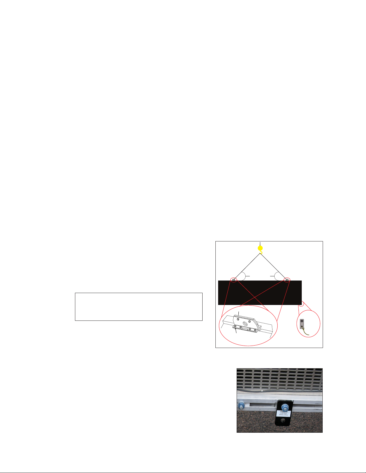
3 Display Installation������������������������������4
Display Installation Preparation................4
Display Installation .....................................4
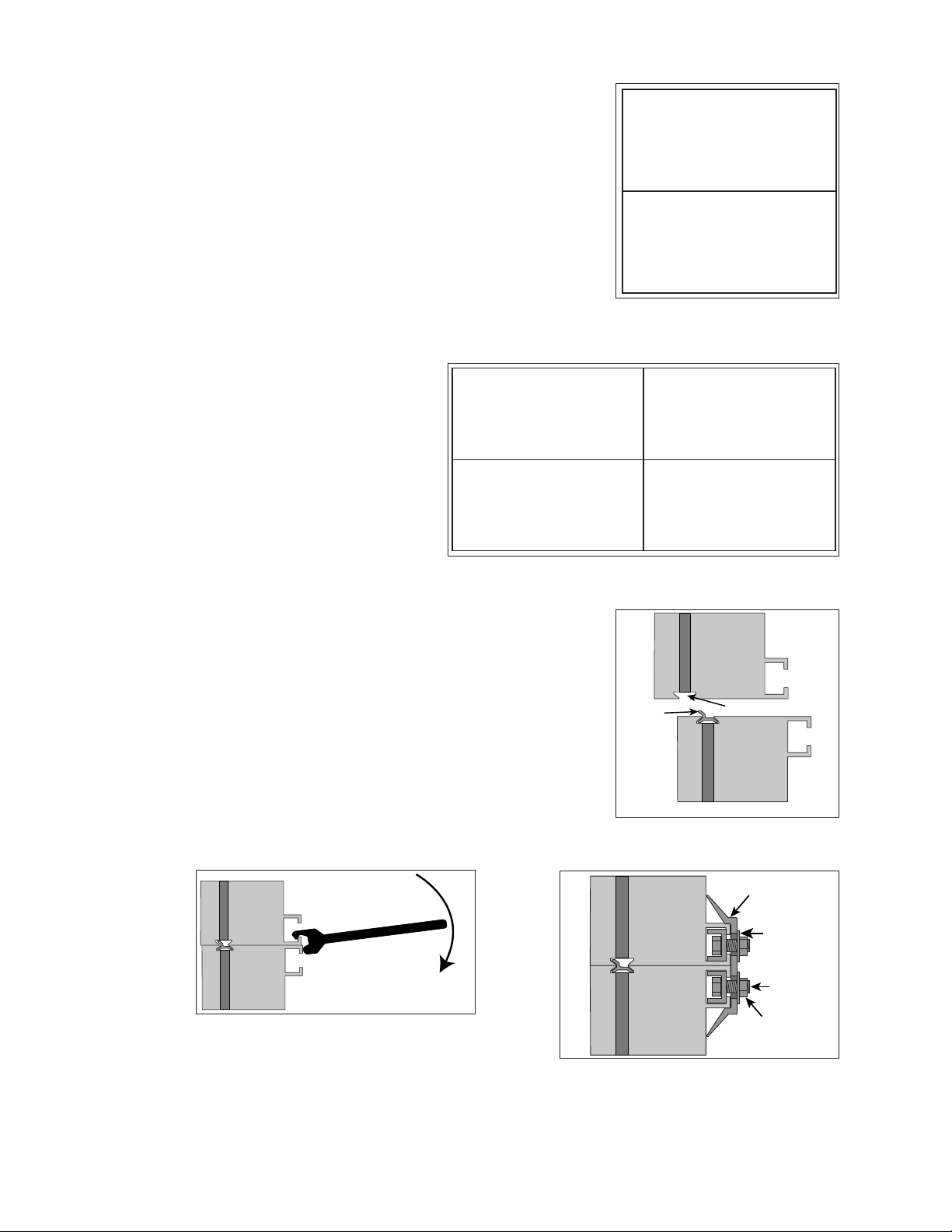
4 Section Splicing ����������������������������������6
Display Section Numbering ......................6
Section Splicing..........................................6
5 Electrical Installation ��������������������������7
Warnings and Disclaimers ........................7
Power Requirements .................................7
Main Disconnect .......................................7
Conduit.......................................................8
Power Connection ....................................8
Earth Ground Installation ..........................9
Important Points About Grounding .........9
6 Signal Cable Installation ������������������10
Primary/Mirror Display Interconnections
...................................................................10
Sectional Display Signal Connections...10
7 System Start-Up Procedure��������������11
Boot Sequence........................................11
Start-Up Checklist ....................................11
8 Network and Communication
Installation �����������������������������������������12
Network and Communication
Installation Recommendations ..............12
Requirements For Communication
Through A Network .................................12
Connecting A Display to A DHCP
Network.....................................................12
Display Currently Congured For DHCP
(Default)�������������������������������������������������12
Network Requirements .....................12
Installation/Start-up Steps.................12
Display Congured For Static IP
Address��������������������������������������������������12
Network Requirements .....................13
Conguration Steps Using IP Address
.............................................................13
Conguration Using DisplayFind To
Discover The Display ����������������������������14
Download DisplayFind......................14
Launch DisplayFind...........................14
Connect To A Display���������������������������15
Connect A Display To A Static IP Network
...................................................................16
Display Currently Congured for DHCP
(Default)�������������������������������������������������16
Network Requirements�������������������������16
Conguration Steps Using IP Address
.............................................................16
Display Congured For Static IP
Address��������������������������������������������������17
Network Requirements .....................17
Conguration Steps Using IP Address
.............................................................17
9 Venus Software Conguration���������19
First-Time Venus Login..............................19
Logging In–Daktronics Web-Hosted
Server�����������������������������������������������������19
Logging In–Customer Local-Hosted
Server�����������������������������������������������������19
Venus Menu Overview............................20
Venus System Setup ................................20
Contact Information and Where to Get
Help ...........................................................21
Telephone ..........................................21
Online .................................................21
10 Display Maintenance�����������������������22
Internal Display Access ...........................22
Ventilation System ...................................23
Display Face Cleaning............................23
Wet Cleaning Process ��������������������������23
Dry Cleaning Process���������������������������23
11 Display Troubleshooting�������������������24
Power and Signal Routing ......................24
Power Routing ���������������������������������������24
Signal Routing ���������������������������������������25

– ii –
Table of Contents
Controller Diagnostics .............................26
PLR Diagnostics .......................................26
PLR Self-Test ..............................................26
Module Diagnostics.................................27
Module Self-Test.......................................27
12 Replacing Parts���������������������������������28
Module Replacement.............................28
Power Supply Replacement ..................28
Controller Replacement.........................29
PLR Replacement ....................................29
13 Daktronics Exchange and Repair &
Return Programs��������������������������������30
Daktronics Exchange and Repair &
Return Programs ......................................30
Exchange Program ������������������������������30
Before Contacting Daktronics�������������30
Repair & Return Program ���������������������31
Shipping Address����������������������������������31
Daktronics Warranty and Limitation of
Liability ......................................................31
A Reference Drawings �������������������������33
B Daktronics Warranty and Limitation
of Liability�������������������������������������������35
C Legacy Remote Display
Conguration ������������������������������������37
Connecting A Display to A DHCP
Network.....................................................37
Display Currently Congured for DHCP
(Default)�������������������������������������������������37
Network Requirements .....................37
Installation/Start-up Steps.................37
Display Congured For Static IP
Address��������������������������������������������������37
Network Requirements .....................37
Conguration Steps Using IP Address�37
Installation/Start-up Steps.................37
Display Congured For Static IP
Address��������������������������������������������������37
Network Requirements .....................37
Conguration Steps Using IP Address
.............................................................38
Conguration Using DisplayFind To
Discover The Display ����������������������������39
Downloading DisplayFind ................39
Launching DisplayFind......................39
Connecting To A Display..................40
Connecting A Display To A Static IP
Network.....................................................41
Display Currently Congured for DHCP
(Default)�������������������������������������������������41
Network Requirements .....................41
Conguration Steps Using IP Address
.............................................................41
Display Congured For Static IP
Address��������������������������������������������������42
Network Requirements .....................42
Conguration Steps Using IP Address
.............................................................42

Introduction
1
1 Introduction
This manual provides the necessary information to install and service a Galaxy® Large
Matrix GS6 series display.
Please read and understand all steps in this manual before beginning the installation
process.
Complete the steps in this manual in order. Contact Daktronics Technical Support with
any questions before or during the installation process.
Limitation of Liability
The factory warranty will be void if:
• The display is not installed according to the steps in this manual.
• Proper electrical service is not provided or the display is not grounded properly.
• Unauthorized modications are made to the display, display cabinet, or the control
system.
Refer to Daktronics Warranty and Limitation of Liability (p�35) at the end of this manual
for the full Daktronics Warranty and Limitation of Liability.
Contact Information
For assistance before, during, or after display installation, please contact Daktronics
Technical Support: 1-800-DAK-TRON (325-8766).
Model Number Guide
Galaxy® Large Matrix GS6 model numbers are dened as follows:
GS6-RxC-M-X-F
GS6 = Outdoor Standard Galaxy®display
R= Number of pixel rows high
C= Number of pixel columns wide
M= Pixel pitch in millimeters
X= LED Color: R (Red); A (Amber); White (W); RGB (Red, Green, Blue)
F= Face setup: SF–Single Face or 2V–Primary/Mirror
Displays are either single face (SF) or two view (2V). In 2V units, the rst display is referred
to as the primary and the second is called the mirror. If the second display is mounted
more than 8' (2.4 m) from the primary display, two primary displays are used.

Installation Preparation
2
2 Installation Preparation
This section explains what to consider before installing a Galaxy® Large Matrix GS6 series
display.
Follow all guidelines and safety precautions in this manual when installing the display. Do
not modify the display or control system in any manner without the written permission of
Daktronics engineering staff.
Any unauthorized modications nullify the display warranty.
Pre-Installation Checklist
• Ensure the display was not damaged during shipping.
• Ensure the mounting structure will provide a straight and square mounting frame for
the display.
• Ensure the support structure can carry the weight of the display and meets local and
national codes.
• Ensure proper power is available at sign structure–refer to the Shop Drawing for
display power requirements.
• Ensure the display cabinet has no holes (accidental or intentional) that will allow
water to enter the display.
• Ensure all display modules are fully latched into the display cabinet.
Structure Requirements
Support structure design depends on mounting method, installation height, display size,
and weight. Because every installation site is unique, Daktronics approves no single
procedure for mounting displays.
Things to consider prior to installation:
• The display mounting requires a continuous horizontal stringer across the back
attached to all display mounting points to provide adequate wind load support for
the cabinet.
• The structure must be able to carry the weight of the display and wind load.
• Display structure and mounting must not obstruct airow–refer to the Shop Drawing
for ventilation space requirements.
• The light sensor must not be obstructed for the display to function properly.
For additional questions about display mounting requirements and specications, refer
to the display Shop Drawing or contact Daktronics Technical Support at 1-800-DAK-TRON
(325-8766).

Installation Preparation
3
Required Tools
The following table lists the minimum tools to have on site for each installation. Daktronics
only provides the specialized tools needed to complete the installation.
Daktronics Provided Customer Provided
Splice Wrench Hex Head Wrenches – 1/8" and 3/16"
Flathead and Phillips Head Screw Drivers
Crane or Lift Truck
Step Ladders
Computer with Venus®Software and Internet access
Ratchet and/or Impact Wrench – 11/16"
Socket Set – Sizes up to 1-1/16" Needed
Tape Measure
Utility Knife

Display Installation
4
3 Display Installation
This section explains the steps necessary for proper lifting and installation of the display to
the sign structure.
Follow all guidelines and safety precautions in this manual when installing the display.
Do not modify the display or control system in any manner without the written permission
of Daktronics engineering staff. Any unauthorized modications will void the warranty.
Display Installation Preparation
• Inspect the display for damage prior to installation
• Use all T-clips for mounting
• Provide an adequate support structure that is straight and level
• Provide adequate ventilation that meets or exceeds display specications listed on
the Shop Drawing
• Use all T-clips for mounting using a continuous horizontal member
• Use all lift eyes when lifting the display
• Do not open the Galaxy® Large Matrix GS6 controller enclosure
• Do not block display ventilation system
• Do not use the lift eyes for display mounting
• Do not hang additional signage from Galaxy® Large Matrix GS6 series display.
Display Installation
1� Use a utility knife to carefully cut away all of
the white packaging material from the display.
Be careful not to damage the face of the
display or LEDs.
Note: If the display is multi-sectional, refer
to Section Splicing (p�6) before
continuing.
2� Attach a crane or lift truck to the lift eyes on
the display's top.
Lift eye spacing is set at Daktronics and should
not be moved. Lift eyes should also remain in
place after installation is complete.
Ensure the angle between the top of the display and
the lifting strap is greater than 55°. Refer to Figure 1.
3� Apply tension to the lift lines.
4� Attach tag lines to the bracket. Refer to Figure 2.
5� Unbolt the display from the shipping braces.
From Back
Tag Line
Tie Off
Angle must be
greater than 55°
Lift-Eye Bolts
Set Bolts
Figure 1: Proper Display Lifting
Figure 2: Tag Line Bracket

Display Installation
5
6� Lift the display off the truck to the display structure.
Note: Do not lift displays in wind speeds greater than 20 mph (32vkph).
7� Mount the display to the structure by welding or bolting all T-clips to horizontal
stringers.
Use all T-clips when mounting the display. Refer to the Shop Drawing for required
T-clip spacing.
8� Remove crane support and tag lines from the display once mounting is complete.
9� Locate the top border caps and install over lift eyes using provided Tek screws.

Section Splicing
6
4 Section Splicing
Display Section Numbering
For displays with multiple sections, each section is
numbered for easy installation. For a two-section display,
the bottom section is 201 and the top section is 101. Refer
to Figure 3.
For four-section displays, when looking from the front, the
lower-left display section is 201 and the section to the
right is 202; the upper row of sections are 101 on the left
and 102 on the right. Refer to Figure 4.
Section Splicing
1� Ensure the splice key is inserted
in the channel of the bottom
section. Refer to Figure 5.
2� Attach a crane or lift truck to
the lift eyes of the top section
and apply tension.
3� Unbolt the top section of the
display from the truck bed and
unbolt the A-frame.
4� Lift the display top section off the truck high enough
to spin around 180°.
5� Starting at one end of the display, use the splice tool
to draw the top section into the bottom until the
splice key is fully engaged. Refer to Figure 6.
6� Ensure display sections are aligned and that LEDs are
also in alignment.
7� Attach the splice plates and splice T-clips along the
section splice. Refer to Figure 7. Use an 11/16" impact
wrench or ratchet to tighten all nuts on the splice
plates and splice T-clips.
Section 201
Section 101
Figure 3: Two-Section Display
Section Numbering
Section 201
Section 101
Section 202
Section 102
Figure 4: Four-Section Display Section Numbering
Top
Section
Bottom
Section
Splice
Key
Splice Channel
Figure 5: Installed Splice Key
Top
Section
Bottom
Section
Figure 6: Aligning Display Sections with
Splice Tool
Splice
Plate
Bolt
Nut
Washer
Display Face
Bottom
Section
Top
Section
Figure 7: Installed Flat Splice Plate

Electrical Installation
7
5 Electrical Installation
This section explains the steps necessary to make nal electrical connections to the
display from the primary power source. For display-specic power requirements, refer to
the Shop Drawing or label on the rear of the display. Follow all installation guidelines.
Warnings and Disclaimers
• Ensure that all electrical work meets or exceeds all local or national electrical codes.
• Provide the required power to the display as listed on the product labels,
specications, or site-specic riser drawings. The conductor size may vary based on
the length of the power run.
• Consider implementing a separate circuit for the display using an isolation
transformer or dedicated transformer.
• Daktronics assumes no liability for any issues caused by line voltage uctuations or
other improper power conditions.
Important Notes
• Qualied personnel must perform electrical installations to prevent injury to personnel
and damage to the equipment.
• Daktronics engineering staff must approve any changes made to the display. Before
altering the display, submit detailed drawings for the proposed modications to the
Daktronics engineering staff for evaluation and approval, or the warranty will be void.
• Improper installation could result in serious damage to the equipment and could be
hazardous to personnel.
• Size conductors of circuits that deliver power to the display according to national
and local electrical codes so the power distribution system delivers full-load power to
the display while maintaining a voltage within 5% of the utility nominal voltage.
Power Requirements
• Install the display according to all applicable local and national electrical codes. This
includes proper grounding and bonding of the display.
• Do not connect the display to any voltage other than that listed on the Daktronics
product label.
• Displays use single-phase power. Proper power installation is imperative for display
operation.
Main Disconnect
Daktronics requires using a power disconnect switch with the display. A disconnect allows
all ungrounded conductors to be disconnected near the point of power connection.
Locate the disconnecting means either in a direct line of sight from the display or so it
can be locked in the open position. This ensures that power is not reconnected while
service personnel work on the display.

Electrical Installation
8
Conduit
Daktronics does not provide conduit. Separate conduit must be used to route:
• Power
• Signal IN wires to the signal termination enclosure (when applicable)
• Signal OUT wires (if not using the provided interconnect cable)
For power, displays have either a J-box or a 3/4" conduit access hole located in the lower
right corner on the rear of the display. For signal, displays have signal input quick
connects or etched drilling guides for conduit.
Power Connection
1� Review the power requirements for the display.
Requirements are found on the display Shop
Drawing or label on the rear of the display.
2� Route conduit from the main distribution
panel/disconnect to each display power
entrance. Each display section has a power
entrance and requires a dedicated circuit.
3� Remove the four screws that attach the power
entrance access door. Refer to Figure 8.
4� Connect conduit to the 2" (51 mm) Myers hub
at the left of the power entrance box.
5� Feed power cable from the conduit into the
power entrance box.
6� Connect primary power lines to appropriate
taps in enclosure. Refer to Figure 9. Refer to
label on enclosure for the wiring diagram.
7� Reinstall power entrance cover.
8� Connect grounding electrode to ground lug,
shown in Figure 10, on each section.
Figure 8: Display Power Requirements
Label
Figure 9: Power Entrance Box
Figure 10: Ground Lug

Electrical Installation
9
Earth Ground Installation
To connect the Galaxy® Large Matrix
GS6 series display to an earth-ground
electrode, follow these steps:
1� Install an earth-ground electrode
(ground rod, ground plate, etc.)
near the base of the display. Refer to
Figure 11 for guidelines.
Note: Each display face requires an
earth-ground electrode.
2� Connect a copper wire from the
grounding electrode to the ground
lug on the rear of the display.
3� Bury any copper cable or grounding electrodes so they are below grade.
Important Points About Grounding
All components of a display system—including but not limited to displays, control
equipment, and connected peripheral equipment—must be electrically grounded.
Only qualied individuals may perform electrical work, including verication of ground
resistance. Daktronics is not responsible for improper grounding or damage incurred as a
result of improper grounding.
Grounding methods must meet the provisions of all applicable local and national codes.
Inspect and verify all grounding methods meet the provisions of all applicable local and
national codes.
Proper grounding is necessary for reliable equipment operation and general electrical
safety. Failure to properly ground the display system may void the warranty, disrupt
operation, damage equipment, and cause bodily harm or death.
Primary
Mirror
Display
Ground Lug
Thermal Weld
Connection
Preferred Conduit
Copper Ground Conductor
(One Per Display Face)
Copper Ground Rods
8 ft.(2.5 m)
min.
8 ft.(2.5 m)
min.
Figure 11: Proper Display Grounding

Signal Cable Installation
10
6 Signal Cable Installation
For specic details on installing the communications, consult the quick guide and manual
included with the communication equipment. Each type of communication is listed
below with its document number.
Communication Type Communication Manual Communication Quick Guide
Wireless Ethernet Bridge DD1685027 DD1417586
Ethernet DD1417609 DD1417573
Fiber Ethernet DD1417611 DD1417581
These are the standard communication types, but each site is unique and may include
additional equipment. If problems arise, contact the display's service company or
Daktronics Customer Service.
Primary/Mirror Display Interconnections
For data to get from the Primary display to the Mirror
display, the ber interconnect cable must be connected.
This cable typically comes attached to the rear of the
display.
1� Locate cable and unpackage.
2� Connect one end of the cable to J34 on the rear of
the Primary display. Refer to Figure 12.
3� Connect the other end of the cable to J32 on the rear
of the Mirror display.
4� Coil up any excess cable and secure it to prevent
vandalism and weather-related damage.
Note: Anchor points are found on each fan hood for securing excess cable.
Sectional Display Signal Connections
For sectional displays, data is transmitted from one section to the next through ber
cables connected to the outside of each section.
Each section has multiple jacks labeled either A or B. Refer to DWG-3141399 for correct
cable routing between display sections. A label on the rear of the display also illustrates
how to connect the cables.
Figure 12: Signal Out Jack

System Start-Up Procedure
11
7 System Start-Up Procedure
Displays show a boot sequence about two minutes after power is turned on. This
information is very useful when conguring the display in Venus®software. Prior to turning
the display on, make sure display communications and any network connections have
been made.
Boot Sequence
Description
Firmware Name and Version
Display Size (Pixels High by Pixels Wide)
DHCP Name Assigned
IP Address and State
MAC Address
Conguration Port
Status Port
Management Port (Used to Access Conguration)
Description
Start-Up Checklist
• Conrm power is correctly connected to the display.
• Conrm there is sufcient power according to display requirements.
• Conrm a main disconnect is installed.
• Conrm the display is grounded per local and national codes.
• Conrm that all communication equipment is installed according to provided
documentation.
• Conrm that any necessary network connections have been made.
• Conrm ability to log in to venus�daktronics�com
• Inspect peripheral equipment (temperature sensor, light sensor, etc.) for proper
installation.

Network and Communication Installation
12
8 Network and Communication Installation
This section explains how to set up communications with a Galaxy® Large Matrix GS6
series display through a network or an individual computer. Refer to the available
standard communication options in the provided quick guides and reference manuals
for more information.
Daktronics is not responsible for setting up a customer's network system neither a Local
Area Network (LAN) nor a Wide Area Network (WAN).
See Legacy Remote Display Conguration (p.35) for legacy display conguration.
Network and Communication Installation
Recommendations
• Complete all network and communication installation prior to turning on the display.
• Have a laptop on site with Internet access (preferred).
• Work with the customer's IT professional for network integration.
Galaxy® Large Matrix GS6 series displays use DHCP by default, which allows automatic
display conguration by the customer's network, and eliminates manual conguration of
the player.
When the display is connected to a network that supports DHCP, a default DHCP name
similar to "DMP8.xx.xxxx" or "DMP5.xx.xxxx", where "xxxx" represents a unique identier for
the display, is shown in the display boot sequence.
Requirements For Communication Through A Network
The display must be allowed to establish an outgoing internet connection on Port 80
(http) and Port 443 (https).
Connecting A Display to A DHCP Network
Display Currently Congured For DHCP (Default)
The following steps explain how to congure a display and connect to a network that
supports DHCP. Using the display's DHCP name is desired for communication.
Network Requirements
• DHCP Server
• Existing Network
• Available network port, congured properly
Installation/Start-up Steps
1� Ensure the display has an established link with the network.
2� Turn on the display.
Display Congured For Static IP Address
The following steps explain how to recongure a display for DHCP network when it has
previously been congured for a static IP address.

Network and Communication Installation
13
Network Requirements
• Existing Network
• Available network port, congured properly
• PC
• Web browser
Conguration Steps Using IP Address
1� Connect a computer to the display.
2� Turn on the display.
3� Observe boot sequence–recongure computer to the same IP address range as the
display and same subnet.
4� Manually enter display IP address in web browser followed by :85 (for example,
http://169.254.13.87:85) to identify the correct connection port.
5� Enter Dak as the user name and DakPassword! as the password in the Windows
Security window.
6� Click OK to connect to the display (refer to the help le for additional information
about the conguration utility).
7� Click the Network tile.
8� Click Automatic under both the IP and DNS Conguration headings.

Network and Communication Installation
14
9� Click Save.
10� Log out of the conguration utility.
11� Turn off the display.
12� Disconnect the computer from the display and connect the display to the network.
13� Ensure the display has an established link with the network.
14� Turn on the display.
Conguration Using DisplayFind To Discover The Display
Download DisplayFind
Download the DisplayFind utility from the Internet.
1� Open Internet Explorer or Firefox web browser.
2� Navigate to dakles.daktronics.com
3� Click Venus 1500 > Utils > DisplayFind > DisplayFind.exe.
4� When prompted, select Run to complete the installation of the DisplayFind utility or
Save to the computer for later use.
Launch DisplayFind
Double-click the DisplayFind icon on your desktop.
Each item listed at the top of the DisplayFind utility should have a green check mark.
Refer to the explanations below for what each item means. If an item has a red X next to
it, click it for additional information or to access the download.
The Current User Is An Administrative User On This Computer
• The user must have administrative rights to install SilverlightTM.
• Once SilverlightTM is installed, administrative rights are not necessary.
Windows Firewall Exception Is Currently Enabled
• Windows rewall should be temporarily disabled to allow discovery responses to be
received from any displays.
• Other third party Antivirus/rewall applications (McAffee, Symantec, ZoneAlarm, etc.)
should also be temporarily disabled.
SilverlightTM Version–A green checkmark tells you SilverlightTM 3.0 or newer is installed.

Network and Communication Installation
15
Connect To A Display
1� Select the Network Adapter used to communicate with your display.
2� Click the Find Displays button to detect any displays using the selected network
adapter.
3� Detected displays are listed in the bottom window of the utility.
4� Click the desired display (VIP5-xx-xxx) to launch the conguration utility within your
web browser.
Note: Refer to the conguration utility help le for additional information.
• After running DisplayFind to determine the display's static IP address,
reconguration of the computer to the same IP address range and subnet may
be required.
5� Follow the steps in Conguration Steps Using IP Address (p.13).

Network and Communication Installation
16
Connect A Display To A Static IP Network
Display Currently Congured for DHCP (Default)
The following steps explain how to set a static IP address on the display.
Network Requirements
• Existing Network
• Available network port, congured properly
• PC
• Internet Explorer or Firefox web browser
Conguration Steps Using IP Address
1� Connect a computer to the display.
2� Congure the computer for DHCP.
3� Turn on the display.
Note: Both the display and the computer should time out searching for a DHCP
server and fall back to auto IP addresses of 169.25x.x.x.
4� Observe boot sequence–recongure computer to same in the IP address range as
the display and same subnet.
5� Manually enter display IP address in web browser followed by :85 (for example,
http://169.254.13.87:85) to identify the correct connection port. Refer to the
Conguration Using DisplayFind To Discover The Display (p.14).
6� Enter User Name Dak and Password DakPassword! in the Windows Security window.
7� Click OK to connect to the display (refer to the help le for additional information
about the conguration utility).
8� Click the Network tile.
9� Click Manual under the IP Conguration heading.
Other manuals for Galaxy GS6
2
Table of contents
Popular Matrix Switcher manuals by other brands

Extron electronics
Extron electronics Matrix 50 Series user manual

Thinklogical
Thinklogical MX48 product manual

Vanco
Vanco EVOLUTION EVMX42MV quick start guide

Binary
Binary B-660-MTRX-8X8 installation manual

Extron electronics
Extron electronics MAV Plus Series user manual

AMX
AMX AVS-OP-3604-117 Specifications