manuals.online logo
Brands
  1. Home
  2. •
  3. Brands
  4. •
  5. Danfoss
  6. •
  7. Water Pump
  8. •
  9. Danfoss PAHF 20 User manual

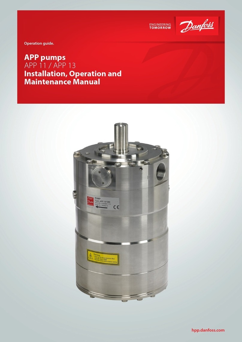
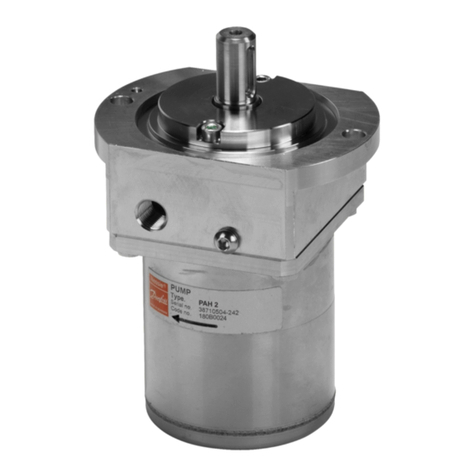
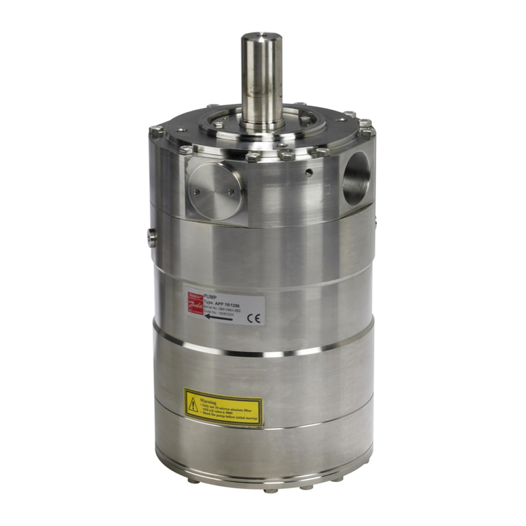
Danfoss PAHF 20 User manual

180R9170
521B1096 DKCFN.PI.010.A2.5B 10-2009
180R9170
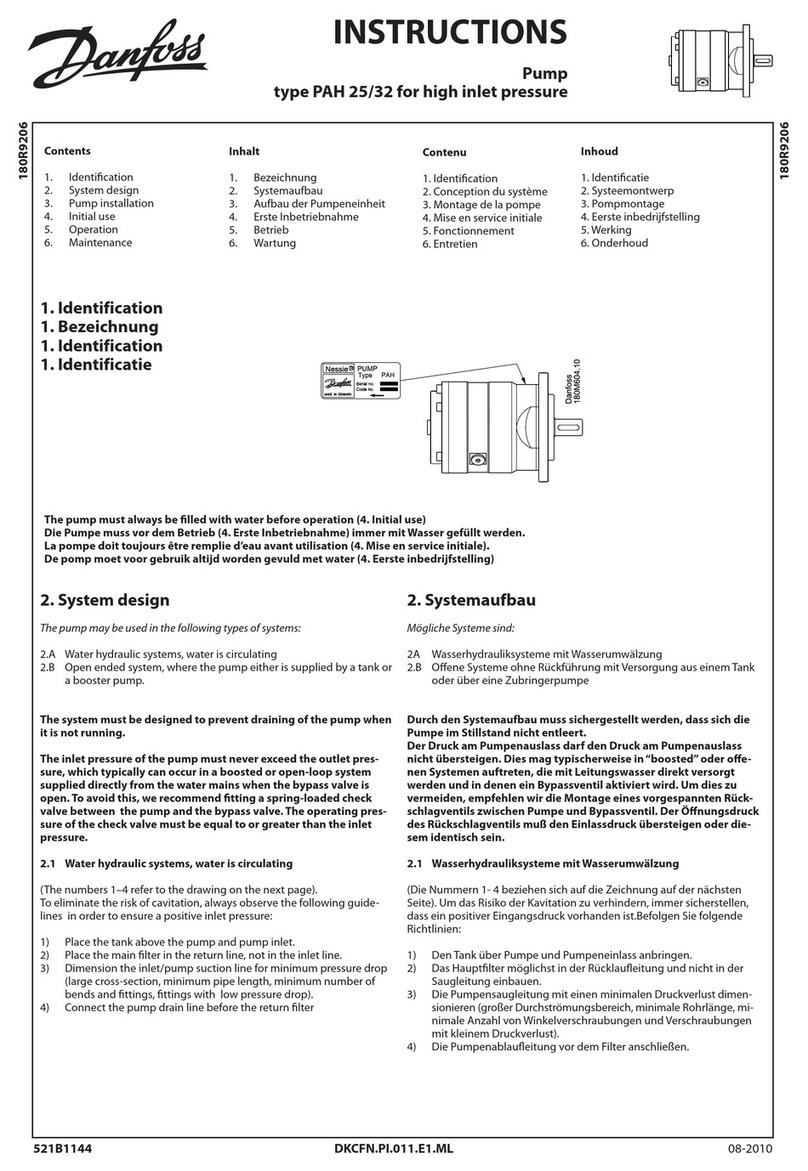
INSTRUCTIONS
Pump
type PAHF 20/25/32/40
Contents
1. Identication
2. System design
3. Building up the pump unit
4. Initial start up
5. Operation
6. Service
Inhalt
1. Bezeichnung
2. Systemaufbau
3. Aufbau der Pumpeneinheit
4. Erste Inbetriebnahme
5. Betrieb
6. Wartung
2. System design
Systems can be either:
2.1 Water hydraulic systems, in which the water is recirculated back to
tank.
2.2 Open-ended systems with water supply from a tank.
2.3 Open-ended systems with direct water-supply (boosted pressure).
The design of the system must ensure that selfemtying of the pump
during standstill is avoided.
The minimum boost pressure is 1 bar atm(14psi) and the maximum
peak pressure is 30 bar (450 psi). The recommended normal boost
pressure is 1-6 bar atm (14-90 psi). Max 10 bar (150 psi) during static
standstill.
The inlet pressure of the pump must never exceed the outlet pressure.
This may typically occur in boosted or open-ended systems
with supply direct from the tap and where a bypass valve is activated.
2.1 Closed water hydraulic systems, water recirculated
(The numbers 1- 3 refer to the drawing below).
In order to eliminate the risk of cavitation, always ensure a positive
inlet pressure by observing the following guidelines:
1) Place the tank above pump and pump inlet.
2) Place the main lter in the return line and not in the suction line.
3) Dimension the inlet line with a minimum pressure loss (large
ow area, minimum length of pipe, minimum number of bends/
connections, ttings with small pressure losses).
1. Bezeichnung
2. Systemaufbau
Mögliche Systeme sind:
2.1 Wasserhydrauliksysteme in denen das Wasser in den Tank zurückge-
leitet und wieder verwendet wird.
2. Oene Systeme ohne Rückführung mit Versorgung aus einem Tank.
2.3 Oene Systeme ohne ohne Rückführung, mit direkter Wasserversor-
gung (erhöhter Ansaugdruck).
Der Systemaufbau muß sichern, daß sich die Pumpe im Stillstand
nicht entleert.
Der min. Spitzendruck ist 1 bar atm (14psi) und der Max Spitzen-
druck ist 30 bar (450 psi). Empfohlener Normal-Einlaβdruck ist
1-6 bar atm (14-90 psi). Max 10 bar (150 psi) während statischen
Stillstands
Der Druck am Pumpeneinlaß darf den Druck am Pumpenauslaß
nicht übersteigen. Dies mag typisch in “boosted”oder oenen Systemen
auftreten, die mit Leitungswasser direkt versorgt werden
und in denen ein Bypassventil aktiviert wird.
2.1 Wasserhydrauliksysteme, Wasser rezirkuliert
(Die Nummern 1- 3 beziehen sich auf die unten abgebildete
Zeichnung). Um das Risiko der Kavitation zu verhindern, immer sichern,
daß ein positiver Eingangsdruck vorhanden ist.Befolgen Sie folgende
Richtlinien:
1) Den Tank über Pumpe und Pumpeneinlaß anbringen.
2) Das Hauptlter möglichst in der Rücklaueitung und nicht in der
Saugleitung einbauen.
3) Die Saugleitung mit einen minimalen Druckverlust dimensionieren
(großer Durchströmungsbereich, minimale Rohrlänge, minimale An-
zahl von Winkelverschraubungen, und Verschraubungen mit klei-
nem Druckverlust).
1. Identification
2
Re 2.2 Open-ended systems, water supply from tank
(The numbers 1- 3 refer to the drawing below)
In order to eliminate the risk of cavitation, observe the following
guidelines:
1) Place the tank above the pump (water level in the tank should al-
ways be above the pump).
2) Place the inlet lter before the tank.
3) Dimension the inlet line to obtain minimum pressure loss (large ow
area, minimum pipe length, minimum number of bends/connec-
tions, ttings with small pressure losses).
2.2 Offene Systeme mit Wassertank
(Die Nummern 1- 3 beziehen sich auf die unten abgebildete Zeichnung)
Um das Risiko der Kavitation zu vermeiden, befolgen Sie folgende Richt-
linien:
1) Den Tank über der Pumpe hoch anbringen (der Wasserstand im Be-
hälter sollte immer über Pumpenniveau sein).
2) Das Zulaulter vor dem Behälter anbringen.
3) Die Saugleitung im Hinblick auf minimalen Druckverlust dimensio-
nieren (großer Durchströmungsbereich, minimale Rohrlänge, mini-
male Anzahl von Winkelverschraubungen und Verschraubungen mit
kleinem Druckverlust).
In order to avoid the risk of cavitation, the inlet pressure at the pump
must be min. 1 bar atm (2 bar abs), 14 psi (30 psi)
The inlet line connection must be properly tightened, as possible en-
trance of air will cause cavitation.
The suction conditions can be optimized according to below guide-lines
on page 3.
Um die Gefahr der Kavitation zu vermeiden muß der Druck am Pumpen-
einlaß min. 1 bar atm (2 bar abs), 14 psi (30 psi) sein.
Die Montage der Einlaßleitung muß korrekt ausgeführt werden, da ein
evtl. Lufteintritt Kavitation verursachen wird.
Die Saugverhältnisse können gemäß Richtlinien auf Seite 3 optimiert
werden.
Re 2.3 Open-ended systems with direct water supply
The pump is supplied with water direct from the water
supply or from a booster pump. Recomended normal
boost pressure is 1-6 bar (14-90 psi)
2.3 Offene Systeme mit direkter Wasserversorgung
Die Pumpe wird direkt vom Trinkwassernetz oder von einer Zwischen-
pumpe versorgt. Empfohlener Normal-Einlaβdruck ist 1-6 bar (14-90 psi)
3
2) In 90° bends 2) In 90° Winkeln
1) In smooth pipes and hoses 1) In geraden Rohren und Schläuchen
2.4 General comments on
Filtration
A good filtration is vital to ensure a long and trouble free life of the
pump.
When selecting a lter or strainer, please note that lter materials should
be compatible with water, i.e. should neither corrode or dissolve. Also be
aware of the electrochemical series of the applied materials.
Main lter must have a neness of 10 μm abs.ß10 >5000.
The pressure loss across the lter should be monitored.
Please contact the Danfoss Sales Organization for further lter
details.
Water tank
Must be made of corrosion-proof material such as stainless steel or
plastic and must be sealed to prevent entrance of impurities from
the environment.
Automatic pressure equalization between tank and surroundings must
be ensured.
Inlet from the water supply (the return line) and inlet to the pump should
be placed in opposite ends of the tank to calm and deaerate the water,
and to ensure optimum opportunity for particles to settle.
2.4 Generelle Bemerkungen über
Filtrierung
Eine gute Filtrierung ist für eine lange Lebensdauer der Pumpe uner-
läßlich.
Wenn Sie Filter oder Sieb wählen, beachten Sie bitte, daß das Filtermate-
rial Wasserverträglich sein muß, d.h. es darf weder korrodieren noch was-
serlöslich sein. Beachte auch die elektrochemischen Ausführungen der
verwendeten Materialien.
Das Hauptlter muß eine Feinheit von 10 μm Abs. ß10 >5000
haben.
Der Druckverlust über das Filter sollte überwacht werden.
Nach weiteren Einzelheiten über Filtrierung erkundigen Sie sich
bitte bei Ihrer Danfoss Verkaufsorganisation.
Wassertank
Muß aus nichtrostendem Material wie rostfreiem Stahl oder Plastik sein.
Um das Eindringen von Schmutzpartikeln aus den Umgebungen zu ver-
hindern, muß der Behälter verschlossen sein.
Der Druckausgleich zwischen Tank und Umgebung muß gewähr-
leistet sein.
Wasserversorgungseinlaß und die Saugleitung der Pumpe sollten mög-
lichst weit auseinander angebracht werden um das Wasser in einem Zu-
stand zu stillen und dadurch die best möglichen Voraussetzungen für
das Absetzen von Partikeln zu schaen.
General guidelines for calculation of pressure losses Generelle Richtlinien für die Berechnung von Druckverlusten
4
Pump suction line should be placed relatively high above the tank bot-
tom in order to prevent settled particles from being led into the pump.
We recommend a separation ("wall") to separate the inlet from the outlet
end of the tank.
Die Zulaueitung sollte so hoch wie möglich über dem Tankboden
angebracht werden. Dies verhindert, daß bereits abgesetzte Partikel
wieder aufgewirbelt und von der Pumpe angesaugt werden.
Wir schlagen eine Trennung ("Wand") vor, die den Einlaß von der
Auslaßseite des Tanks trennt.
Monitoring
It is recommended to continuously monitor the following conditions:
• Water level (if a tank is used)
• Filter contamination
• Pressure (inlet side of the pump)
• Temperature (inlet side of the pump)
3. Building up the pump unit
3.1 Mounting
Überwachung
Wir empfehlen laufende Überwachung folgender Bedingungen:
• Wasserstand im eventuellen Tank
• Verschmutzung des Filters
• Druck (Ein- und Auslaßseite der Pumpe)
• Temperatur (Einlaßseite der Pumpe)
3. Aufbau der Pumpeneinheit
3.1 Montage
If alternative mounting is desired, please contact the Danfoss Sales
Organization.
Choose proper tolerances to ensure an easy mounting of the elastic cou-
pling without use of tools.
Please take care to observe the recommended length tolerances of the
chosen coupling, as an axial force on the pump shaft will prevent the
pump from generating pressure (and over time damage the pump).
Wünschen Sie eine alternative Montage, fragen Sie bitte Ihre
Danfoss Verkaufsorganisation.
Wählen Sie angemessene Toleranzen, um eine einfache Montage der
elastischen Kupplung ohne Einsatz von Werkzeugen zu sichern.
Beachten Sie bitte, daß die empfohlene Längentoleranz eingehalten
wird, da eine Axialkraft auf die Pumpenwelle den Druckaufbau verhin-
dern (und damit die Pumpe allmählich beschädigen wird).
A: Elastic coupling / Elastische Kupplung
B: Bell housing / Kupplungsgehäuse
C: Motor shaft / Motorwelle
min. 3 mm.
MAX 0,25 MM
5
3.2 Direction of rotation
Is indicated by means of an arrow at the inlet side of the pump.
3.2 Drehrichtung
Wird durch einen Pfeil seitlich der Einlaßseite der Pumpe angezeigt.
3.3 Orientation
The pump can be mounted/orientated in any horizontal position and it
can be mounted/orientated in the vertical position with the shaft up-
wards. The pump cannot be vertically mounted/orientated with the shaft
facing downwards.
3.4 Protection from too high system pressures
The pump should be protected against too high pressure by means of a
pressure relief valve or a bypass/unloading valve placed on the pressure
side
The valve should be placed as close to the pump as possible.
The opening characteristics of the valve must not result in peak pressures
higher than 200 bar (3000 psi).
3.3 Einbaulage
Die Pumpe kann in beliebiger horizontaler Position montiert/ausgerich-
tet werden und in vertikaler Position mit der Welle nach oben montiert/
ausgerichtet werden sein. Die Pumpe kann nicht mit der Welle nach un-
ten montiert/ausgerichtet werden.
3.4 Überdruckabsicherung
Die Pumpe sollte mit einem Überdruckventil oder einem Druckentla-
stungsventil auf der Druckseite gegen zu hohen Systemdruck Druck ab-
gesichert sein.
Das Ventil sollte so nah wie möglich an der Pumpe montiert werden.
Die Önungscharakteristik des Ventils darf keine Höchstwerte über
200 bar zulassen (3000 psi).
CCW (counter clock wise) CW (clock wise)
6
PAHF 20/25/32/40
Outlet (O) Inlet (I) Bleeding (C) Gauge
Thread/Gewinde, ISO
Use PAHF adaptor
or VRHF100 Relief
valve (to be or-
dered seperately)
1 1/4”BSPP with
20mm long
thread
M6 (width across
at = 5mm)
1/4”BSPP with
15mm long
thread
Max tighten torque/
Max. Anzugsmoment
Screws for
adaptor block:
4 pcs M8 30NM
150 Nm*
(133 lbf/ft) -15 Nm*
(11 lbf/ft)
• Recommended torque values refer to steel washers containing a
rubber sealing element.
4. Initial start-up
Before start-up, loosen the top bleeding plug“C”. When water appears
from the bleeding plug, retighten the plug.
• Die empfohlenen Werte beziehen sich auf Stahlunterlegsscheiben
mit Gummidichtung.
4. Erste Inbetriebnahme
Vor der Inbetriebnahme, lösen Sie die obere Entlüftungsschraube “C”.
Wenn Wasser aus der Entlüftungsschraube austritt, diese erneut anzie-
hen.
The piping/hose between inlet lter and pump must be ushed prior to
initial start up of the pump to ensure that impurities are removed.
Warning:
Make sure that the direction of rotation of the electric motor corresponds
to the direction of rotation of the pump.
Um Schmutzpartikel zu entfernen müssen Rohre und Schläuche
zwischen Einlaβlter und Pumpe vor der ersten Inbetriebnahme der
Pumpe durchgespült werden.
Warnung:
Beachten Sie, daß die Drehrichtung vom Elektromotor mit der Drehrich-
tung der Pumpe übereinstimmt.
C
I : Inlet
O : Outlet
C : Bleeding
XO: Gauge port*
Parallel key: 8 × 7 × 32 DIN 6885
I : Einlaß
O : Auslaß
C : Entlüftung
XO: Messanschluss*
Paßfeder: 8 × 7 × 32 DIN 6885
*Eine 1/4”Anschlüsse an der Einlaβseite für wahlweisen Anschluβ von
z.B. Schaltern für Niederdruck und Temperatur.
Ein 1/4”Anschluss an der Auslaβseite für wahlweisen Anschluβ von z.B.
einem Druckgeber.
*There is one 1/4”ports on the inlet side for optional mounting of ie
switches for low pressure and temperature.
There is one 1/4”port on the outlet for optional mounting of i.e. pres-
sure transducer.
C
I
X0
O
C
3.5 Connections 3.5 Anschlüsse
XO
7
5. Operation
5.1 Water quality
Water of drinking water quality, conrming to the EEC directive 98/83/EC
and without abrasive sediments, demineralized water, de-ionised water,
softened water and RO water.
Please contact Danfoss sales organization in case of doubt.
5.2 Temperature
Fluid temperature:
Min. +3°C to max. +50°C.
Ambient temperature:
Min. 0°C to max. 50°C.
Storage temperature:
Min. -40°C to max. +70°C.
To protect the pump from too high uid temperature, a temperature
switch of 50 degrees Celsius should be mounted on the inlet side. If the
whole pump ow is bypassed over the relief valve, then the uid tempe-
rature will go up relatively fast.
5.3 Pressure
The inlet pressure must be min. 1 bar (atm) (14 psi) equals 2 bar abs (45
psi). At lower pressures the pump run a risk of cavitating, resulting in
damage of the pump.
Short term inlet pressure peaks must not exceed 30 bar (450 psi).
It is recommended that the normal boost pressure is 1-6 bar atm
(14-90psi).
If it is unknown what the peak inlet pressure can be, then there should
be a 15 bar (225psi) safety relief valve on the inlet side of the pump.
Max. pressure on the pump's outlet line should be limited at 160 bar
(2400 psi) continuously.
Short-term pressure peaks (e.g. in connection with closing of a
valve) of up to 200 bar (3000 psi) are acceptable.
It is recommended to have a check valve on the outlet side of the pump
to protect the pump from high pressure going backwards into the pump
when it is turned o. Especially, when using exible hose or more pumps
are installed in the same system.
5.4 Dry running
When running, the pump must always be connected to the water supply
in order to avoid damage if it should run dry.
In systems with water tank it is recommended to build in a level
gauge in the tank to avoid the risk of running dry.
In systems with a boost pump, it is strongly recommended to have a low
pressure switch mounted on the water inlet side set at minimum 2 bar
(30 psi)
5.5 Disconnection
If the inlet line is disconnected from the water supply, the pump will be
emptied of water through the disconnected inlet line.
When starting up again, follow the bleeding procedure described under
section 4: Initial start up.
5.6 Storage
When preparing the pump for long-term storage or for temperatures be-
low the freezing point, ush the pump with an anti-freeze medium type
monopropylene glycol to prevent internal corrosion or frost in the pump.
For further information on anti-freeze media, please contact the Danfoss
Sales Organization.
Recommended procedure:
5.6.1 Water hydraulic systems in which the water is recirculated
back to tank and re-used.
5.6.2 Open-ended systems with water supply from tank.
5.6.3 Open-ended systems with direct water supply.
5. Betrieb
5.1 Wasserqualität
Wasser von Trinkwasserqualität, nach EU Direktive 98/83/EC und ohne
abresiven Sedimenten, VE-Wasser, enthärtetem Wasser und
Umkehrosmose-Wasser.
Im Zweifelsfall fragen Sie bitte die Danfoss Verkaufsorganisation.
5.2 Temperatur
Druckmitteltemperatur:
Min. +3°C bis max. +50°C.
Umgebungstemperatur:
Min. 0° bis max. 50°C.
Lagertemperatur: Min. -40° bis max. +70°C.
Um die Pumpe gegen zu hohe Flüssigkeitstemperatur zu schützen, muss
ein 50 gr. C Temperaturschalter an der Einlaβseite montiert werden.
Wenn der ganze Pumpendurchuss über das Druckbegrenzungsventil
geleitet wird, wird die Flüssigkeitstemperatur relativ schnell steigen.
5.3 Druck
Der Einlaßdruck muß min. 1 bar absolut (atm) gleich 2 bar abs sein.
Ein geringerer Druck wird zu Kavitation führen.
Kurzfristige Einlaβ-Druckspitzen müssen nicht 30 bar überschreiten.
Es ist zu empfehlen, dass der normale Einlaβdruck 1-6 bar ist (14-90psi).
Bei unbekannten Spitzen Einlassdruck, sollte ein 15 bar (225psi) Überdruck-
ventil an der Einlassseite der Pumpe montiert sein.
Der max. Druck in der Druckleitung der Pumpe sollte auf 160 bar kontinu-
erlich begrenzt werden.
Kurze Druckspitzen (z.B. in Verbindung mit dem Schließen eines Ventils)
sind bis zu 200 bar möglich.
Um bei abgeschalteter Pumpe Rückwärts-Hochdruckdurchuss zurück in
die Pumpe zu vermeiden, ist es zu empfehlen, ein Rückschlagventil an der
Auslaβseite der Pumpe zu installieren, besonders in Fällen wo exible
Schläuche und mehrere Pumpen im selben System installiert sind.
5.4 Trockenlauf
Wenn die Pumpe läuft, muß sie immer an der Wasserversorgung ange-
schlossen sein, um Schäden infolge des Trockenlaufes zu verhindern.
In Anlagen mit Wassertank empfehlen wir, daß ein Wasserstandsanzeiger in
den Tank eingebaut wird, um das Risiko des Trockenlaufes zu vermeiden.
In Systemen mit einer Einlaβpumpe, ist es eindringlich zu empfehlen,
einen Druckschalter für Niederdruck an der Wasser-Einlaβseite auf mini-
mum 2 bar (30psi) eingestellt zu installieren.
5.5 Demontage
Wenn die Anschlußleitung von der Wasserversorgung demontiert wird,
entleert sich die Pumpe. Bei erneuter Inbetriebnahme, befolgen Sie bitte
die Entlüftungsprozedur unter Abschnitt 4: Erste Inbetriebnahme.
5.6 Lagerung
Vor längerdauernder Lagerung der Pumpe, oder wenn die Temperatur
unter dem Gefrierpunkt absinkt, sollte die Pumpe mit einem Frostschutz-
mittel Typ Monopropylen Glycol durchgespült werden um Korrosion oder
Frostschäden im Inneren der Pumpe zu verhindern. Für weitere Einzel-
heiten über Frostschutzmittel verständigen Sie bitte die Danfoss Verkaufs-
organisation.
Empfohlene Prozedur:
5.6.1 Wasserhydrauliksysteme in denen das Wasser rezirkuliert
und an den Tank zurückgeleitet wird.
5.6.2 Oene Systeme ohne Rückführung mit Versorgung aus einem Tank.
5.6.3 Oene Systeme ohne ohne Rückführung, mit direkter Wasser versor-
gung.
8
5.6.1 Water hydraulic systems, water recirculated
1. Disconnect the power pack from the system.
2. Empty the tank of water. Fill up the tank with anti-freeze
medium to a level well above the suction line.
3. Start up the power pack and, for a couple of minutes, in a
closed loop system let the anti-freeze medium run back to
tank through the pressure relief valve or the bypass valve.
4. Empty the tank of the anti-freeze medium. Empty the pump
through the lower bleeding plug.
The pump is now protected against internal corrosion and frost.
5.6.2 Open-ended systems with water supply from tank.
1. Empty the tank of water and empty the pump housing through the
lower bleeding plug. When the pump is empty, retighten the plug.
2. Through the upper bleeding plug, ll the pump housing with anti-
freeze medium. Pour anti-freeze medium into the tank.
Connect a hose to the outlet of the pump and lead the other end
of the hose back to tank.
3. Quickly start and stop the pump. Make sure that the pump does not
run dry.
The pump is now protected against internal corrosion and frost.
5.6.3 Open-ended systems with direct water supply.
1. Disconnect the water supply to the pump.
2. Through the lower bleeding plug, empty the pump housing of wa-
ter and close it again.
3. Connect the pump to a tank of eg. 25 litre (6 gal.) of anti-freeze
additive. Connect a hose to the inlet port of the pump and via an-
other hose return the ow from the outlet port port to the
tank with anti-freeze additives.
4. Quickly start and stop the pump. Make sure that the pump does not
run dry.
The pump is now protected against internal corrosion and frost.
6. Service
6.1 Periodic maintenance
The PAHF pump is designed so that lubrication follows from the water it-
self and there is thus no oil in the pump.
The pump requires no periodic replacements of seals and valve parts.
6.2 Repair
In case of irregular function of the pump, please contact the
Danfoss Sales Organisation.
5.6.1 Wasserhydrauliksysteme, Wasser rezirkuliert
1. Die Verbindung zwischen Pumpenstation und System trennen.
2. Das Wasser aus dem Tank ablassen. Den Tank mit Frost-
schutzmittel bis reichlich über der Ansaugleitung auüllen.
3. Die Pumpenstation anlassen, und einige Minuten lang das Frost-
schutzmittel in einem geschlossenen Kreislauf über Druckentla-
stungs- oder Umlaufventil zurück an den Tank laufen lassen.
4. Das Frostschutzmittel aus dem Tank ablassen. Die Pumpe
durch den unteren Entlüftungsstopfen entleeren.
Die Pumpe ist jetzt vor Innenkorrosion und Frostschäden geschützt.
5.6.2 Oene Systeme mit Wassertank.
1. Das Wasser aus dem Tank ablassen, und das Pumpengehäuse durch
den unteren Entlüftungsstopfen entleeren.
Den Stopfen erneut anziehen, wenn die Pumpe leer ist.
2. Das Pumpengehäuse durch den oberen Entlüftungsstopfen mit
Frostschutzmittel auüllen. Frostschutzmittel in den Tank einfüllen.
Einen Schlauch an den Ausgang der Pumpe anschließen, und das
andere Schlauchende zum Tank zurückführen.
3. Die Pumpe nur kurzzeitig anlaufen lassen und abstellen.
Beachten Sie, dass die Pumpe nicht trocken läuft.
Die Pumpe ist jetzt vor Innenkorrosion und Frostschäden geschützt.
5.6.3 Oene Systeme mit direkter Wasserversorgung.
1. Die Trinkwasserversorgung an die Pumpe abstellen.
2. Das Wasser aus dem Pumpengehäuse durch den unteren
Entlüftungsstopfen ablassen und danach wieder schließen.
3. Die Pumpe mit einem Behälter mit z.B. 25 Liter Frostschutzmittel
verbinden. Einen Saugschlauch an den Eingang der Pumpe an-
schließen und das Frostschutzmittel aus dem Pumpenausgang
durch einen weiteren Schlauch in den Tank zurückleiten.
4. Die Pumpe kurzzeitig anlaufen lassen und abstellen.
Beachten Sie, daß die Pumpe nicht trocken läuft.
Die Pumpe ist jetzt vor Innenkorrosion und Frostschäden geschützt.
6. Wartung
6.1 Periodische Wartung
Die PAHF-Pumpe ist so konstruiert, daß die Schmierung durch das Was-
ser erfolgt; es gibt also kein Öl in der Pumpe.
An der Pumpe ist kein periodischer Austausch von Dichtungen und Ven-
tilteilen erforderlich.
6.2 Reparatur
Bei Funktionsstörungen setzen Sie sich bitte mit Ihrer Danfoss Verkaufs-
organisation in Verbindung.

This manual suits for next models

3

Other Danfoss Water Pump manuals

Danfoss APP W HC Series User manual

Danfoss

Danfoss APP W HC Series User manual

Danfoss Nessie Plug&Spray NPS 1CS Installation and operation manual

Danfoss

Danfoss Nessie Plug&Spray NPS 1CS Installation and operation manual

Danfoss BOCK HG4 User manual

Danfoss

Danfoss BOCK HG4 User manual

Danfoss H1P Series User manual

Danfoss

Danfoss H1P Series User manual

Danfoss Series 90 User manual

Danfoss

Danfoss Series 90 User manual

Danfoss Series 42 User manual

Danfoss

Danfoss Series 42 User manual

Danfoss APP 21-43 User manual

Danfoss

Danfoss APP 21-43 User manual

Danfoss PAHT Series User manual

Danfoss

Danfoss PAHT Series User manual

Danfoss ASV-PV DN 15 User manual

Danfoss

Danfoss ASV-PV DN 15 User manual

Danfoss Optyma OP-HRSM0750NC211Q User manual

Danfoss

Danfoss Optyma OP-HRSM0750NC211Q User manual

Danfoss Series 90 Manual

Danfoss

Danfoss Series 90 Manual

Danfoss ASV-P User manual

Danfoss

Danfoss ASV-P User manual

Danfoss APP 0.6 User manual

Danfoss

Danfoss APP 0.6 User manual

Danfoss H1 Series User manual

Danfoss

Danfoss H1 Series User manual

Danfoss APP 21-43 User manual

Danfoss

Danfoss APP 21-43 User manual

Danfoss Series 45 User manual

Danfoss

Danfoss Series 45 User manual

Danfoss APP 13 User manual

Danfoss

Danfoss APP 13 User manual

Danfoss APP series User manual

Danfoss

Danfoss APP series User manual

Danfoss PAHT G User manual

Danfoss

Danfoss PAHT G User manual

Danfoss PAH Series User manual

Danfoss

Danfoss PAH Series User manual

Danfoss PAHT Instruction Manual

Danfoss

Danfoss PAHT Instruction Manual

Danfoss KSV Series User manual

Danfoss

Danfoss KSV Series User manual

Danfoss 180F4161 User manual

Danfoss

Danfoss 180F4161 User manual

Danfoss Series 40 M46 Tandem User manual

Danfoss

Danfoss Series 40 M46 Tandem User manual

Popular Water Pump manuals by other brands

Champion Pump CPSTEP5 Series installation manual

Champion Pump

Champion Pump CPSTEP5 Series installation manual

Espa ACUARIA07S Series instruction manual

Espa

Espa ACUARIA07S Series instruction manual

Davey CD40-40 Installation and operating instructions

Davey

Davey CD40-40 Installation and operating instructions

Toyotomi OPT-91UL Installation & operation instructions

Toyotomi

Toyotomi OPT-91UL Installation & operation instructions

Lavor EG-MS 3800 instruction manual

Lavor

Lavor EG-MS 3800 instruction manual

Bestway Inflate Your Fun FLOWCLEAR 58148 owner's manual

Bestway

Bestway Inflate Your Fun FLOWCLEAR 58148 owner's manual

Gude GDT 1200 Translation of the original instructions

Gude

Gude GDT 1200 Translation of the original instructions

ProMinent Beta BT4a Operating instructions manual

ProMinent

ProMinent Beta BT4a Operating instructions manual

jurop RV360 manual

jurop

jurop RV360 manual

Pfeiffer Vacuum ATH 3200 MT operating instructions

Pfeiffer Vacuum

Pfeiffer Vacuum ATH 3200 MT operating instructions

Hi-Force HEP3 instruction manual

Hi-Force

Hi-Force HEP3 instruction manual

Pentair BVM32 Series Installation and operating instructions

Pentair

Pentair BVM32 Series Installation and operating instructions

Intex Krystal Clear SF90220T owner's manual

Intex

Intex Krystal Clear SF90220T owner's manual

Kampa Breeze PU0161 user guide

Kampa

Kampa Breeze PU0161 user guide

Grundfos CM Installation and operating instructions

Grundfos

Grundfos CM Installation and operating instructions

Graco G Series Instructions-parts list

Graco

Graco G Series Instructions-parts list

Taconova TACOFLOW2 quick guide

Taconova

Taconova TACOFLOW2 quick guide

Kremlin-Rexson EOS 02-C85 Disassembly/Reassembly

Kremlin-Rexson

Kremlin-Rexson EOS 02-C85 Disassembly/Reassembly

manuals.online logo
manuals.online logoBrands
  • About & Mission
  • Contact us
  • Privacy Policy
  • Terms and Conditions

Copyright 2025 Manuals.Online. All Rights Reserved.