Component Testing Procedures
!
WARNING
To avoid risk of electrical shock, personal injury or death, disconnect power to oven and discharge capacitor
before servicing, unless testing requires it.
16500023 October 2013
©2013 ACP, Inc.
2
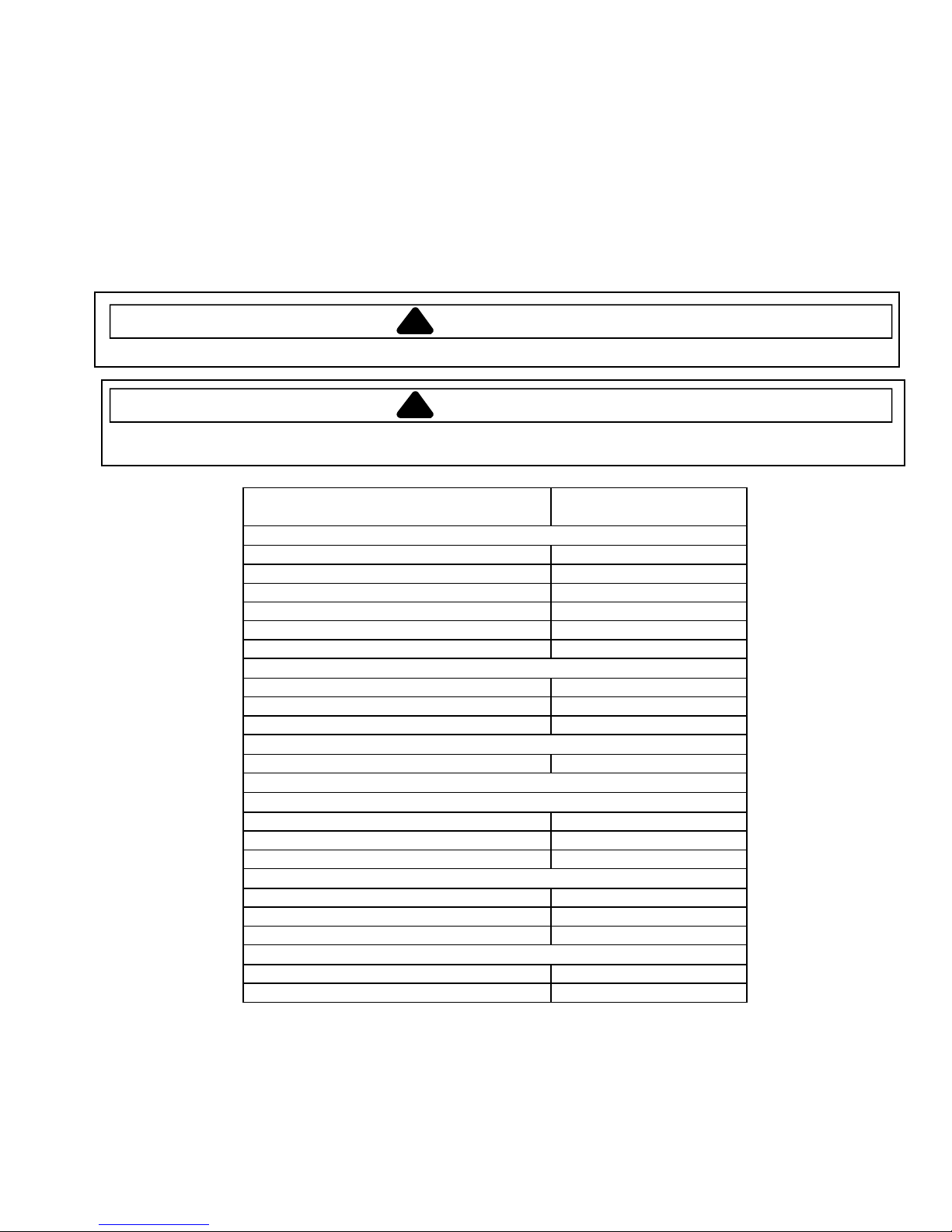
Illustration Component Testing Results
Thermal cutout Disconnect all wires from TCO.
Measure resistance across terminals.
Cavity TCO ...........................................
Magnetron TCO ....................................
Opens at 230°F (110°C)
Closed at 140°F (60°C) and
Opens at 320°F (160°C)
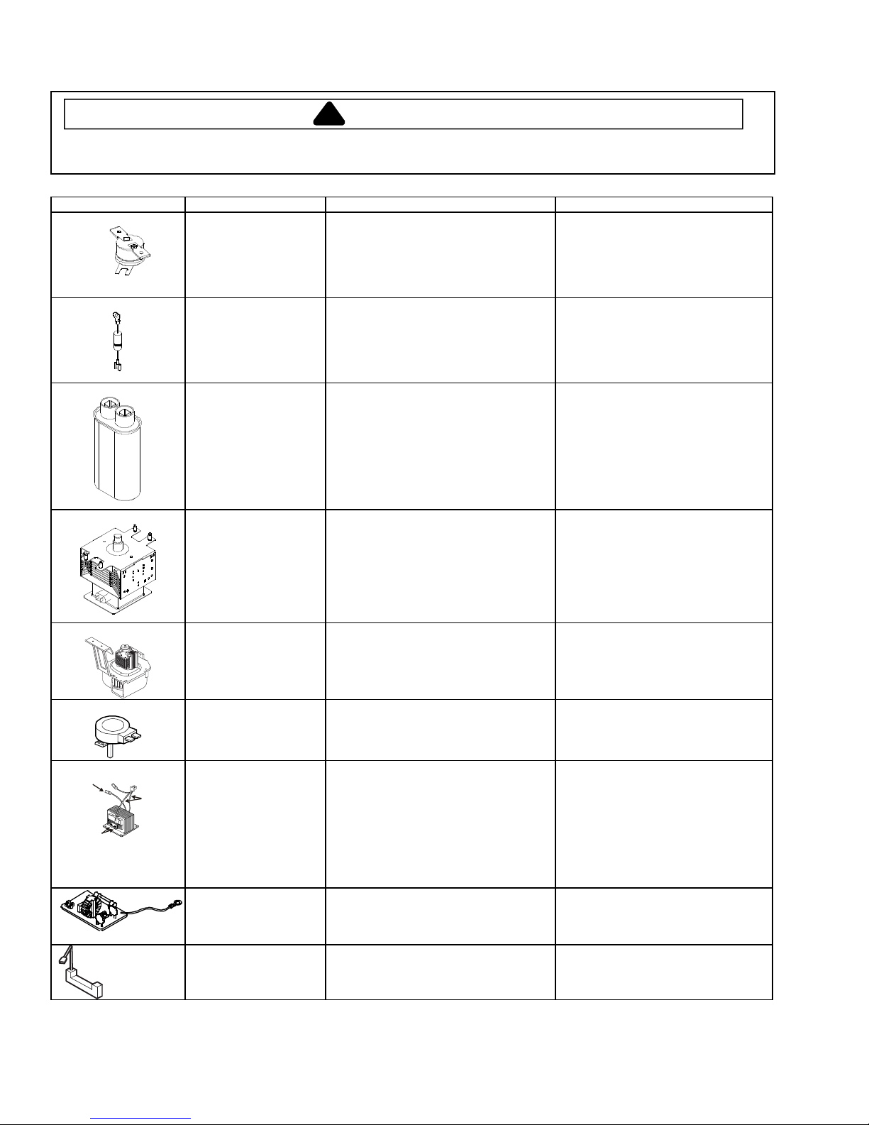
Diode Discharge Capacitor
Remove diode lead from capacitor and
connect ohmmeter.
Reverse leads for second test.
Infinite resistance should be
measured in one direction and 50KΩ
or more in the opposite direction.
NOTE: Ohmmeter must contain a
battery of 6 volts minimum.
Capacitor Discharge Capacitor
Remove wires from capacitor terminals
and connect ohmmeter, set on highest
resistance scale to terminals.
Also check between each terminal and
capacitor case.
Between Terminals: Meter should
momentarily deflect towards zero
then return to over 5 MΩ. If no
deflection occurs, or if continuous
deflection occurs, replace capacitor.
Terminal to Case: Infinite resistance
Magnetron Discharge Capacitor
Remove wires from magnetron and
connect ohmmeter to terminals. Also
check between each terminal and
ground.
Between Terminals: Less than 1 Ω
Each terminal to ground measures
Infinite resistance.
Note: This test is not conclusive. If
oven does not heat and all other
components test good replace the
magnetron and retest.
Blower motor Remove all wires from motor.
Measure resistance across coil.............
Approximately 28 – 35 Ω
Stirrer motor Remove all wires from motor.
Measure resistance across terminals....
Approximately 12 – 14 KΩ
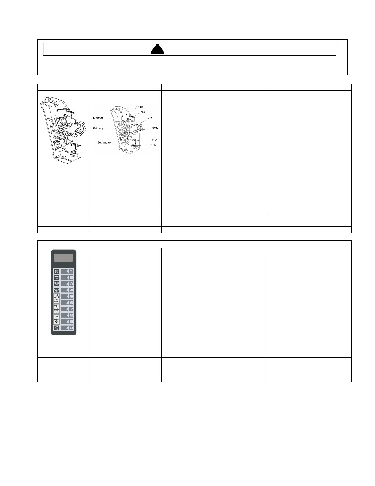
Primary
Transformer
Discharge Capacitor
Remove all wires from terminals.
Measure resistance from:
Primary................................................
Filament...............................................
Secondary to Ground screw on
transformer stack.................................
Less than <1
Ω
Less than <1
Ω
Approximately 90-100
Ω
Noise filter board Power In terminals ................................
Power Out terminals..............................
120 VAC
120 VAC
If no power in, check power outlet.
If no power out, check fuses.
Circuit Protector Measure resistance across terminals.... Between Terminals: Less than 1
Ω


 Operating and installation instructions")