DanPumps S-WN Series User manual

Installation Guide
Wastewater pumps - S-WN series
Version 1.0 2015End-of-life, units has to be recycled in accordance with local regulations.

2
1. Content
2. Pump labels .................................................................................................................................................................. Page 3
3. Applications.................................................................................................................................................................. Page 3
4. Technical specication.............................................................................................................................................. Page 4
5. Handling ........................................................................................................................................................................ Page 5
6. Pump installation........................................................................................................................................................ Page 5
7. Electrical installation ................................................................................................................................................. Page 6
8. Operation ...................................................................................................................................................................... Page 7
9. Service & maintenance............................................................................................................................................. Page 7
10. CE Decleration ............................................................................................................................................................. Page 8

3
2. Pump Labels
Sondex wet-end label Example of Motor label
Technical informations subject to change without notice.
3. Applications
This installation and service manual are valid to the pump type S-WN series.
The series are manufactured in S-WN1, S-WN2, S-WN3 and S-W4.
The S-WN pumps are single stage, and non-self-priming pumps.
The pump is built as end-suction pump, and driven with a standard norm motor.
The pump is designed for pumping clean water, wastewater and waste water with contaminants.
Impeller model has dierent selections.
The S-WN can be delivered with other motor brand after choice.
Atex motor is an option
WARNING
The pumps must never be used in ammable or explosive media. If there are local restrictions concerning re
risks they must be obeyed at all time. The pumps meet EU’s machine directive, see declaration of conformity
at the back of this manual. DanPumps guarantees that the pumps’ airborne noise level does not exceed the
noise level of 74 dbA (at normal operation).
WARNING
If people can get physical contact with the pump or the uid that is being pumped at e.g. open excavations,
building sites or the like, a fault circuit-breaker (HFI or HPFI) must be mounted in the electrical installation.
If the pump is used in oceans, lakes etc. there must be a minimum safety distance of 20 meters between the
pump and any persons in the water. The national country and local standards has at all time to be observed
NOTE that in swimming pools there are special safety restrictions.

4
4. Technical specication
The S-WN pumps are built with motor in 3-phased version for 50 or 60 Hz.
Volt selection between 230/400 and 400/690 after choice. Please see motor label for accurate motor
information on this pump.
Motor space heater 1x230vac. 50watt up to 100watt. Always secure with extern fuse.
PTC resistance has 200-250ohm at 20ºC. (U = 7,5V max)
Höyer electric motors are type approved by BV, GL and ABS (design approval).
Ambient temperature: up to max. 40ºC. Media temperature: -5ºC to 100ºC
The motor are CE marked according to the Low Voltage Directive 2006/95/EC.
Pump housing: Gray cast iron GJL-250 (GG25) (Stainless steel is an option for WN3)
Pump impeller: Ductile cast iron GJS-400-15 (GGG-40). (Stainless steel is an option)
Pump shaft: Stainless cast steel W. Nr. 1.4401 / AISI 316
O-rings: Nitrile / NBR.
Seal type: Please ask technical department.
Motor protection
Degree of protection is standard IP55, and insulation class is F. Tested after standard IEC 60034-2-1.
The electro motor has built-in thermal PTC resistor in the stator.
The PTC resistance 200-250 ohm at 20ºC. (U = 7,5V max)
The IE2 motor has standard tropical windings.
The IE3 motor has tropical windings as an option.
Performance curve

5
GENERAL TOLERANCES:
Format:
Sheet:
Scale:
DWG NO.
TITLE:
SONDEX
REV.
ISO 2768-m
S-WN2-150 M160M
S-WN2-150
A4
1 of 1
1:20
C
2
3
1
4
B
A
D
E
F
Pump ESBXJOHT

6
5. Handling
The pump must be packaged properly during transport to avoid damage to the pump or surroundings. It can
be transported and/or stored in vertical or horizontal position.
Always place the pump on a stable surface, so it cannot tip over during service, transport, testing and
installation.
For storage for long periods of time the pump must be serviced and checked again before use. Before
electrical connection the impeller shall be turned by hand to ensure the correct friction of the mechanical
seal.
Accidents in relation to installation can be minimized by taking care. Be especially careful with the pump’s
weight and the risk of electrical accidents.
When lifting with hoisting equipment, these must always be of the correct dimensions with regard to the
lifted weight. Never walk under hanging loads.
6. Pump Installation
The pipe system must have at least the same section (DN) as the pump connections.
To prevent stresses on the body of the pump, the installation, pipes and associated connection elements.
Pipes must be correctly aligned with the pump without using force, whilst attempting to ensure that both
the intake and discharge pipes are secured independently as close to the pump as possible.
Never run the pump with both the suction side and the pressure side blocked.
Cavitation may occur if the pump’s intake becomes obstructed or if the NPSH value is too low, causing
damage to the internal elements of the pump. (provide the right suction conditions)
Intake.
All pipe systems containing water must be equipped with valves to prevent ooding during pump
maintenance. Connection elements that may cause air pockets should not be used under any circumstances.
User larger pipes whenever needed to maintain the water speed below 1.2 m/s (4 feet per second).
The intake pipe must be one continuous run from its starting point to the pump. In order to prevent air
pockets and the intake pipe must never be positioned higher than the water level or the level of the pump.
Whenever reducers are required to connect the pump, we recommend the use of concentric reducers.
Discharge.
In order to reduce load losses, we recommend the use of pipes of same (DN) or larger diameter than the
pump discharge. Connection elements that may cause air pockets should not be used under any circumstances.
The diameter of the pipes used, ought to be such, which ensures the water speed remains below 2 m/s (7 feet
per second).
Pump priming.
Never run the pump when dry. The water acts as a coolant for the mechanical seal.
If the pump is operated when dry, the mechanical seal may be damaged, causing leaks and expensive repair.
Damaged seal by dry-run is not covered by the warranty.
If the water level is below the level of the pump intake, in an“open tank” installation, then use a low
resistance ball check valve on the end of the suction side.

7
7. Eletrical Installation
Work is only permitted to be carried out by qualied specialists and must to be carried out in accordance
with local regulations. Before work commences, ensure that all power is switched o and cannot be switched
on again accidental. This also applies to the auxiliary power circuits, e.g. anti-condense heaters.
Check that supply voltage and frequency are the same as rated data.
Motors can be used with a supply deviation of ± 5% voltage and ± 2% frequency, according to IEC60034-1
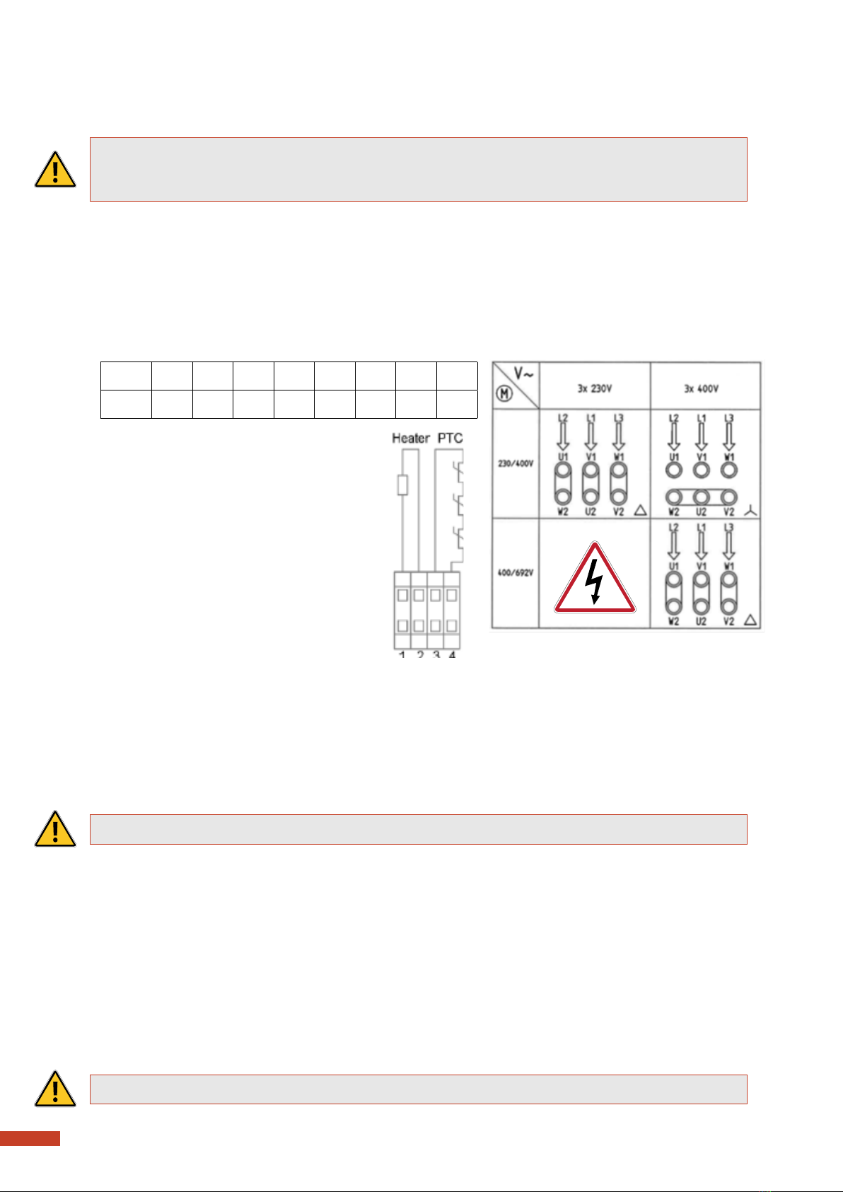
Connection diagrams for main supply and accessory as PTC or heater are located inside the terminal box.
Connections must be made in such a way as to ensure that a permanently safe electrical connection is
maintained, both for the main supply and the earth connection. We recommend that crimped connections
are made in accordance with IEC 60352-2. Use always overload switch.
Tightening torques for terminal board screws:
Thread M5 M6 M8 M10 M12 M16 M20 M24
T.(Nm) 2.5 3.5 7 12 18 35 55 80
Ensure that the terminal box is clean and dry.
Unused glands must be closed with blind caps.
Check the terminal box gasket before it
is remounted.
The pump must be mounted with a motor
guard and a ground fault circuit breaker.
PTC terminals: No. 3 - 4
Motor space heater: No. 1 - 2
See also motor label inside the
motor terminal box.
8. Operation
Before the pump is started, the rotation direction must be checked. At start the motors starting torque will
cause the pump to jerk, and therefore has the pump to be mounted rm to the base.
Before start, the pump must be fully assembled and ready for operation.
At wrong start reaction, two phases must be switched. See the connection diagram.
NOTE: Wrong rotation or cavitation in the pump can make a loud noise.
9. Service and Maintenance
Before any inspection, service or repair of the pump, it has to be physically disconnected from the power
supply. Remove connectors or dismount the wires on the electric board. An emergency stop can be released
or be defective and start the pump by mistake.
All pumps require regular control and preventive maintenance to operate economically and reliably.
The pump should be checked every 6 months and during possible extreme operating conditions more often.
For complete overhaul of the pump contact an authorised Sondex Pumps workshop or your local Sondex
Pumps dealer. Clean the pump carefully before dismantling it. Follow local and national safety instructions.
NOTE: Make sure the fan cover are clean for dust and ect., so fan wing are able to cool the motor.

8
SonFlow A/S
Nordager 25
DK-6000 Kolding
Denmark
Tel.: +45 86 571 344 info@sonflow.dk
www.sonflow.dk V.A.T. No.: DK 35469605
Overensstemmelseserklæring /
EC declaraon of conformity /
Konformitätserklärung
Producent / Manufacturer / Hersteller
SonFlow A/S
Nordager 25
DK-6000 Kolding
Tel: +45 86 57 13 44
Repræsentant / Representave / Repräsentave
Erklærer på eget ansvar, at følgende produkter /
Declare under our sole responsibility that the products /
Erklärt eigenverantwortlich, daß die Produkte
Som er omfaet af denne erklæring, er i overensstemmelse med følgende standarder /
To which this declaraon relates are in conformity with the following standards /
Auf die sich diese Erklärung bezieht, den folgenden normaven Dokumenten entsprechen
Maskindirekvet / Machinery direcve / Maschinenrichtlinie ...................................... 2006/42/EU Appendix II A
EMC-Direkvet / EMC-Direcve / EMV-Richtlinie ........................................................... EMC 2004/108/EU
Lavspændingsdirekvet / Low Voltage Direcve / Niederspannungsrichtlinie .............. LVD 2006/95/EU
01-11-2019
Aage Søndergaard Nielsen
Managing Director
Spildevandspumpe / Wastewater pump / Abwasserpumpe
Series: S-WN series
Models: S-WN1, S-WN2, S-WN3 and S-WN4

Copyright © 2013 SonFlow A/S
SonFlow A/S can accept no responsibility for possible errors in catalogues, brochures and other printet
materials. SonFlow A/S reserves the right at any time to change the specifications without notice.
SonFlow A/S
Nordager 25
DK - 6000 Kolding
www.sonflow.dk
This manual suits for next models
5
Table of contents
Other DanPumps Water Pump manuals
Popular Water Pump manuals by other brands

Wacker Neuson
Wacker Neuson PT2R OPERATOR'S MANUAL AND PARTS BOOK

EINHELL
EINHELL BG-DP 7835 operating instructions

KINNEY
KINNEY KT VFP Series INSTALLATION OPERATION MAINTENANCE REPAIR MANUAL

vacuubrand
vacuubrand ME 8 Instructions for use

Simpson
Simpson SSTP71007 use and care manual

Simer
Simer BW85 Series owner's manual

Liberty Pumps
Liberty Pumps LSG202A installation manual

Pfeiffer Vacuum
Pfeiffer Vacuum OKTA 8000 G ATEX operating instructions

Mammuth
Mammuth CP180B Installation and operating instructions

SKC
SKC Flite 2 operating instructions

Glentronics
Glentronics PHCC Pro Series Instruction manual & safety warnings

Carrier
Carrier 6 instruction manual