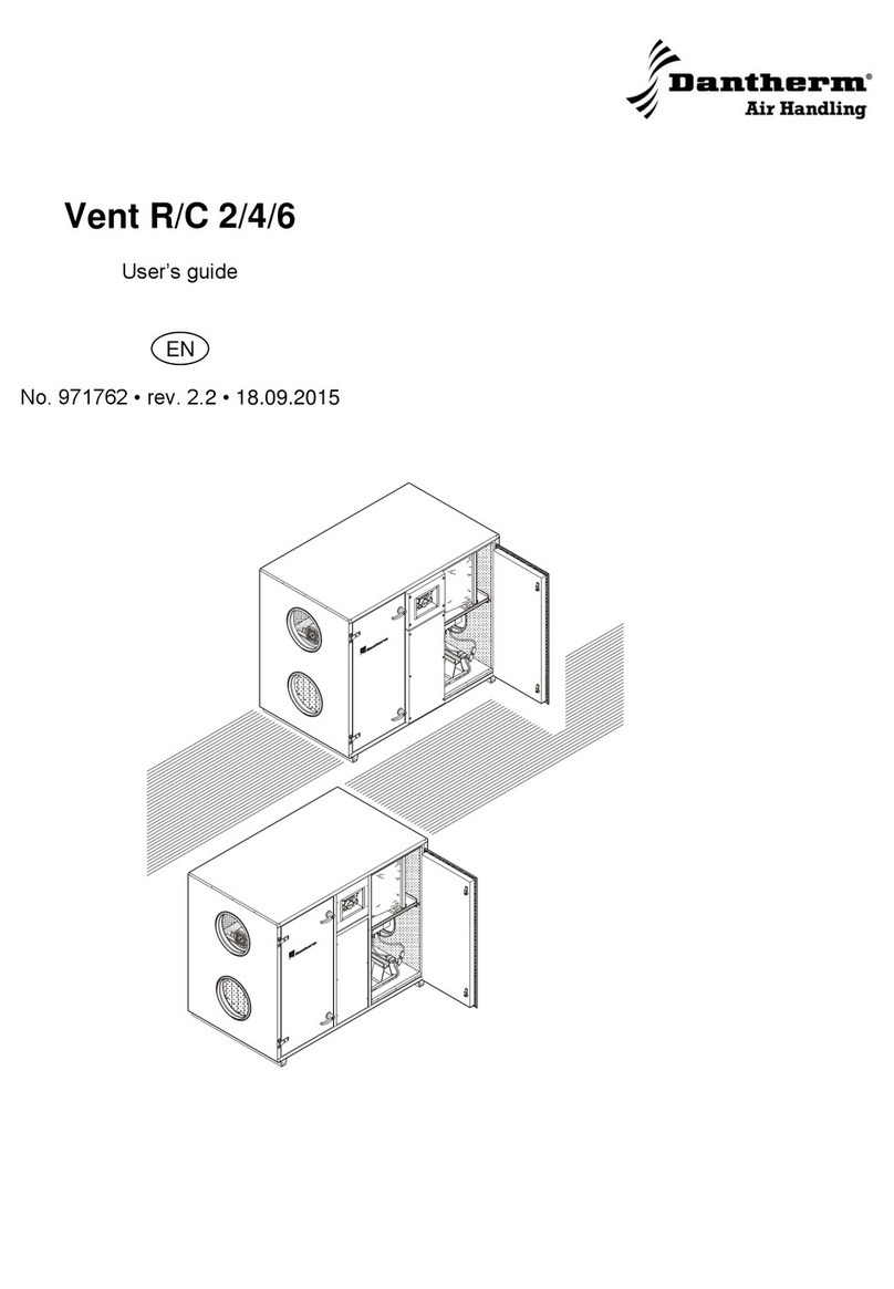
Dantherm HCV 300 User manual

1
093683• Version 1.4• 19.04.2017
<<<<<<<<<
HCV300
Service Manual
Rev. 1.4
EN

2
Der tages forbehold for trykfejl og ændringer
Dantherm can accept no responsibility for possible errors and changes
Irrtümer und Änderungen vorbehalten
Dantherm n’assume aucune responsabilité pour erreurs et modifications éventuelles

3
093683• Version 1.4• 19.04.2017
Introduction
Overview
Introduction This is the service manual for the Dantherm Air Handling A/S
home ventilation unit type HCV300.
Table of contents This manual covers the following topics:
Introduction ..................................................................................................................3
Overview ................................................................................................................3
General information ...............................................................................................4
Product description .......................................................................................................5
General description ................................................................................................5
Description of parts ...............................................................................................8
Description of additional equipment ....................................................................10
Electronic control .................................................................................................11
System operation strategy....................................................................................14
Installation ..................................................................................................................15
Wall mounting......................................................................................................16
Drain....................................................................................................................17
Duct positioning ..................................................................................................18
External connections............................................................................................20
Changing the air flow path...................................................................................21
Calibration ...........................................................................................................23
Setting operating parameters ...............................................................................24
Firmware update ..................................................................................................25
User's guide ................................................................................................................26
General ventilation functions................................................................................27
Use of control panel. ............................................................................................28
Use of LAN interface.............................................................................................30
Service guide...............................................................................................................31
Overview ..............................................................................................................31
Preventative maintenance.....................................................................................32
Troubleshooting...................................................................................................35
Spare parts list .....................................................................................................37
Wiring Diagram ....................................................................................................41
Contact Dantherm................................................................................................43

4
General information
Introduction This section provides general information about the service manual and the unit.
Manual, Product
no.
The product number for this service manual is 093683
Target group The target group for this service manual is:
Everyday users
Technicians who install and maintain the product
Copyright Copying this user guide or parts thereof is not permitted without prior written
permission from Dantherm Air Handling A/S.
Reservations Dantherm Air Handling A/S reserves the right at any time to carry out
changes or improvements to the product and user guide without prior warning or obli-
gation.
EU Declaration of
Conformity
Dantherm Air Handling A/S, of Marienlystvej 65, DK-7800 Skive, Denmark, declares, at
its own liability, that the following product:
352441 HCV300
- which is covered by this declaration, complies with the following directives:
2014/35/EU.......................LVD Directive (low voltage)
2014/30/EU.......................EMC Directive
2014/53/EU.......................R&TTE
- and is manufactured in compliance with the following harmonized standards:
EN 60 335-1:201.............Household & similar electrical appliances, Safety - Part 1
EN 60 335-2-40:2003.....Household & similar electrical appliances, Safety - Part 2-40
EN 61 000-3-2:2014.......Electromagnetic compatibility (EMC) – Part 3-2: Limits
(Harmonics)
EN 61 000-3-3:2013.......Electromagnetic compatibility (EMC) – Part 3-3: Limits (Flicker)
EN 61 000-6-2:2005.......Electromagnetic compatibility (EMC) – Part 6-2: Generic standards
(Immunity)
EN 61 000-6-3:2007.......Electromagnetic compatibility (EMC) – Part 6-3: Generic standards
(Emission)
EN 61 000-6-3/A1:2011..Electromagnetic compatibility (EMC) – Part 6-3: Generic
standards (Emission) - Annex 1
EN 62 233:2008...............Measurement methods for electromagnetic fields of household
appliances
EN 55 014-1:2007...........Electromagnetic compatibility - Requirements of household appliances
etc. Part 1: Emission
EN 55 014-2:015.............Electromagnetic compatibility – Requirements of household appliances
etc. Part 2: Immunity – Product family standard
EN 30 1489-1..................EMC / ERM Part 1
EN 30 1489-3..................EMC / ERM Part 3
EN 30 0200-1:2013-02...EMC / ERM Short Range Device Part 1
EN 30 0200-2:2013-02...EMC / ERM Short Range Device Part 2
EN 30 0200-3:2013-02...EMC / ERM Short Range Device Part 3
Skive, 22.09.2016
Recycling The unit is designed to function for many years. Disposal of the unit must be carried out
in compliance with national legislation and procedures to protect the environment.

5
093683• Version 1.4• 19.04.2017
Product description
General description
Introduction This section provides a description of the unit.
HCV300 Summary The HCV300 unit is designed for the ventilation of private homes.
The heat energy in the impure evacuated air is reused in the unit's heat exchanger, and
heats up fresh air from outside for optimal comfort.
The unit is designed for installation in dry surroundings with temperatures over 12°C.
The air flow path can be altered electronically.
Abbreviations used
in this manual
Common ventilation terms:
Abbre-
viation
Description
T1 Outside air to the unit
T2 Supplied air from the unit to the home (heated in the heat exchanger)
T3 Extract. Evacuated, stale and warm air.
T4 Exhaust air from the unit (cooled in the heat exchanger)
S1 Temperature sensor no. 1
S2 Temperature sensor no. 2
S3 Temperature sensor no. 3
S4 Temperature sensor no. 4
A Indicates mode A, where T2 and T3 are on the left side of the top of the unit.
See page 6
B Indicates mode A, where T2 and T3 are on the right side of the top of the
unit. See page 6
G4 Standard air filter.
F7 Fine filter, pollen filter (Additional equipment)
BP Bypass (prevents overheating of the home on hot days)
IP Unique address for the ethernet port.
DHCP Automatic settings of an ethernet address from an external source on a net-
work (assuming there is connection to Ethernet)
PC Personal computer with Windows
USB Universal serial bus connection
LAN Local area network
WAN Wide area network (internet)
BMS Building Management System
PCB Print Circuit Board
FFC Flat Flexible Cable
Continued overleaf

6
General description, continued
Illustration
Fi
g
. 1
Parts
description
Part Mode A Mode B
Duct connection 1 Extract- T3 Outside air – T1
Duct connection 2 Exhaust – T4 Supply T2
Duct connection 3 Outside air– T1 Extract T3
Duct connection 4 Supply - T2 Exhaust T4
Filter 1 Extraction filter G4 Supply filter G4 or F7
Filter 2 Supply filter G4 or F7 Extraction filter G4
Fan cabinet 1 Extractor fan Supply fan *
Fan cabinet 2 Supply fan* Extractor fan
*Supply fanbox can be fitted with electrical preheat element (accessory)
Continued overleaf
Control panel
Filter 1
Filter 2
Fan cabinet 1
Fan cabinet 2
Bypass
Reverse flow heat exchanger
Duct 1
Duct 2
Duct 3
Duct 4
Water outlet – Mode B Water outlet – Mode A
Front
Seen from below
Duct 4
Mode A Duct 2
Mode B

7
093683• Version 1.4• 19.04.2017
General description, continued
Air flow paths This illustration shows the two air flow paths through the unit.
Air flow can be altered electronically. See page 21.
Air flow path 1
Air flow path 2

8
Description of parts
Introduction This section describes the components in HCV300.
Please see the illustration on page 6 for references.
Cabinet The external parts of the cabinet are manufactured from powder coated, AZ-coated
steel plating.
The internal parts of the cabinet are manufactured from expanded polystyrene (EPS).
Accessories are installed after removing the steel front and EPS doors.
The cabinet is sound and heat insulated with fire retardant polystyrene foam.
The unit is designed for installation in ambient temperatures from 12° to 40°C.
Filters The unit is equipped with a class G4 cassette filter as standard.
These filters protect the heat exchanger and improve the indoor climate by filtering the
air of dust and other particles. An F7 filter (pollen filter) can be purchased as an acces-
sory. The F7 filter is always placed on the supply side - shown on the top of the unit.
Heat exchanger The reverse flow heat exchanger absorbs the heat energy from the evacuated air and
moves it to the fresh air, thereby saving on energy needed for heating.
Fans The supply fan adds fresh air from outside through the heat exchanger to the ventilated
indoor rooms.
The extractor fan sucks out stale and moist air from the home through the heat ex-
changer, where it releases its heat into the fresh outdoor air.
Water outlet The unit is equipped with two drain valves. One of these must be connected to a
drain hose to direct the condensate to a drain.
Correct connection to the drain valves is shown at the top of the unit and on page 6 in
this service manual.

9
093683• Version 1.4• 19.04.2017
Description of parts of parts,
continued
Electronic control Detailed description of the electronic controls page 11,
and user instructions, page 27
Positioning of
parts
Fi
g
. 2
Description of
parts
pos Mode A Mode B
S1 T1 Outside air temperature sensor T3 Extracted air temperature sensor
S2 T2 Supply air temperature sensor T4 Exhaust air temperature sensor
S4 T4 Exhaust air temperature sensor T2 Supply air temperature sensor
S3 T3 Extracted air temperature sensor T1 Outside air temperature sensor
A VOC and RH% sensor (additional
equipment)
n/a (prop)
B n/a (prop) VOC and RH% sensor (additional equip-
ment)
1 T1 Pressure gauge valve for outside
air
T3 Pressure gauge valve for extracted
air
2 T2 Pressure gauge valve for supply
air
T4 Pressure gauge valve for exhaust air
3 T3 Pressure gauge valve for extract-
ed air
T1 Pressure gauge valve for outside air
4 T4 Pressure gauge valve for exhaust
air
T2 Pressure gauge valve for supply air
BP Cable bushin
g
, bypass Cable bushin
g
, bypass
S3
A
BP
3
2
S2
4
S4
S1
B
1

10
Description of additional equipment
Installation of
additional
equipment
The unit is supplied without accessories connected.
Installation of these accessories is described in the documentation included with them.
Electric Pre Heater
The electric heating element heats up the outside air before it comes into the counter
flow heat exchanger and helps to increase comfort in the home during wintertime as
well as preventing the build-up of ice in the heat exchanger.
Humidity and VOC
sensors
This unit can be equipped with humidity (RH%) and/or air quality (VOC) sensors. These
sensors monitor the quality of the air (from) inside the house and adjust the air volume
accordingly. If an HRC 3 remote control is connected to the unit, the level is shown on
the display.
This is called demand controlled ventilation and ensures a high air quality with the low-
est possible energy consumption.
Bypass damper
The motorised bypass damper automatically directs the air outside the heat exchanger
according to demand.
This function is used on sunny days when a cooler outside temperature can help to cool
the air inside.
Hand-held
remote control
(HRC 3)
Adjust the ventilation and keep track of the home's humidity and temperatures via the
large LCD screen in the hand-held remote control. Enable cooling function/bypass (if
this is installed in the HCV unit), select manual ventilation steps or relevant weekly pro-
grams or set the controls to automatic. The remote control can communicate with the
HCV unit at up to 30 metres distance. The remote control can be placed on level surfac-
es or hung up on the wall.
Filters
Replacement filters in sets of 2 standard filters or 1 standard plus 1 F7 (pollen) filter
HAC2
Connect a number of additional accessories to the HCV unit via Home Accessory Con-
troller: HAC2.
Kit for power outlet
at the base of
the unit
The HCV300 unit offers the opportunity to connect a duct for supply air through the
base of the unit. This kit contains an insulated cap, which is necessary to close the vent-
hole at the top of the unit if this connection method is selected.
Contact your dealer for additional accessories and the latest news.

11
093683• Version 1.4• 19.04.2017
Electronic control
Introduction This section provides a detailed description of the electronic controls.
Function The unit's main controls are placed on the main PCB together with other outlets and in-
puts.
The control panel with LED displays is placed under the main controls, and connected to
the
main PCB via FFC.
System
architecture
Illustration of the system control architecture:
Continued overleaf
USB service port
Keypad with LED
Air quality demand
sensor
VOC
HRC 3 wireless
remote
Ethernet router with
DHCP
HCP10 On Modbus
(wired Remote)
HAC2 on MODBUS
(Dantherm
accessory)
2 pce digital in
High/low fan speed
Etc.
Main controller PCB
HCV300 unit
Extract fan
T1-T4
Temperature
sensors
Supply fan
Air humidity (RH%)
demand sensor
Bypass 230VAC
Preheater 230VAC
Accessory modules
230VAC input
External connected items
Building
management
system

12
Electronic control, continued
Illustration
of the control unit
This illustration shows the main PCB and control panel without front cover.
Illustration
of connections
External connections:
Description
of connections
External connections:
Connection Description
230V Connection for 230V power supply.
DIGI IN External digital input, for selection of operation modes
ANTENNA Wireless connection of control panel
MODBUS Modbus connection for external modules
ETHERNET LAN connection
Continued overleaf
Main PCB
USB-B
for servicing
Control panel with LED
External
connections
Internal
connections

13
093683• Version 1.4• 19.04.2017
Electronic control,
continued
Illustration
control panel
Description
control panel
The control panel foil has four buttons with corresponding LED displays.
Four blue LED lights in the middle indicate fan speed regardless of which mode the unit
is operating in.
1 2 3 4 5

14
System operation strategy
Introduction This section describes the operation strategy under a variety of conditions.
See more under user instructions on page 26
Electric preheater If a heating element is mounted it will ensure the heating of fresh outside air while also
reducing the need for defrosting.
The heating element can be enabled/disabled via the remote control (HRC3) in
installer mode
, if the preheating module is set to enable (active) via PC-Tool
during installation.
The heating element is added after the T1 sensor.
If the outside temperature is under -3°C or the supply air is under 16.5°C then
the heating element will function at 10%.
The heating element will increase or decrease the effect by 10% every minute
depending on the T1 or T2 temperature.
If 100% preheater power is not sufficient, boths will be lowered in a balanced
manner.
Setpoints cannot be changed.
Defrosting and fire-
place function
During extremely cold periods with T1 temperatures under -3°C and the exhaust tem-
perature, T4, at less than +2°C there is a risk of condensate in the heat exchanger
freezing to ice, which is inadvisable.
The automatic function prevents this via the following procedure:
Heat is added if a heating element has been mounted.
The supply fan gradually reduces in speed until the minimum RPM is reached.
After 10 seconds at this speed the supply fan stops
while the extractor fan continues to circulate warmer air through the heat ex-
changer, thereby thawing any frost or ice that has formed.
Once T4 has again achieved over +8°C, the supply fan will start at minimum
RPM and gradually increase the speed until the original speed has been
achieved.
The procedure is repeated for as long as is necessary.
If the outside air, T1 is under or at -13°C for more than 4 minutes and 15 sec-
onds – also in defrost mode – the unit will stop for 30 minutes and then resume
normal operations.
This is not possible if the unit is equipped with a heating element.
The default defrost strategy can create underpressure in the house. This may cause
smoke from e.g. a fireplace to be drawn back into the house. Select fireplace mode in
PC-tool house settings. If selected unbalanced defrost is blocked ad the unit will stop
for 4 hours.
Setpoints cannot be changed.
During defrosting an HRC3 remote control will show: "dEF" in the display.
If the frost protection has stopped the unit, the T1 temperature on the display will flash.
Bypass cooling and
summer mode
See page 28

15
093683• Version 1.4• 19.04.2017
Installation
Introduction This section will guide you through mounting and installation.
Important The warranty is restricted to units that have been correctly mounted and installed by
trained personnel only.
Packaging and
contents
HCV300 is delivered packaged in a cardboard box.
Check the box for any transport damage before opening.
Do not use a knife to open the box!
Check the contents of the cardboard box:
Wall bracket and spacers.
Drain hose
Prior to
installation
Before mounting, consider the following:
The unit's controls make it possible to change the air flow path to and from the
unit between the right and left sides (A/B
mode
).
Read more in the general description on page 6.
The change feature ensures optimal installation conditions no matter where the
unit is placed in the building.
The HCV300 unit is designed for mounting in dry surroundings at temperatures
over 12°C, such as technical rooms or other suitable spaces.
Make sure there is plenty of room – especially in front of the unit to ensure it is
accessible for servicing and maintenance.
Ensure that the wall is suitable for carrying the weight of the unit.
Continued overleaf

16
Wall mounting
Mounting of wall
bracket.
Mount the wall bracket as follows:
Step Illustration
Secure the wall
bracket using
these measure-
ments. Ensure you
use suitable
screws and rawl-
plugs.
Mount the two
spacers
at the bottom of
the back of the
unit.
Mount the rubber
strip and lift the
unit up onto the
wall rail.

17
093683• Version 1.4• 19.04.2017
Drain
Warning
Heat recovery of air with a high moisture content leads to condensation in the heat
exchanger. Condensate must be led into a drain, as otherwise it can damage the floor
under the unit.
Drain Connect a drain hose to the correct drain valve at the base of the unit.
The unit is manufactured with blanked drain, see marking at the top of the unit (A/B
mode
)
IMPORTANT:
Make sure that the cap is moved to the correct drain if you change between A/B
mode
,
as otherwise condensate cannot be led out of the unit, and this will then lead to an in-
advisable buildup of water in the unit and the risk of water ingress in the house!
The drain hose must be supplied with a min. 100 mm siphon, as shown below.
Guide the hose to the drain and make sure it does not get exposed to frost.
Fill the hose with water before calibrating the unit.

18
Duct positioning
Warning
Ducts and connectors must be protected and kept closed until the house is ready to be
inhabited.
This is to ensure that no moisture, dirt or dust comes into the ducts, which could create
problems at a later time.
Consider The ducts, which are connected to the unit must have the same diameter as the
connectors or larger.
The dimensions can be seen in the section on technical data.
Duct dimensions and sound absorbers must be in accordance with national standards
and building regulations.
Contact your Dantherm dealer for further information.
Noise and vibrations from the unit to the duct system must be minimised. This can be
achieved by installing sound absorbers on both the supply and exhaust air sides.
Correct duct positi-
oning
See the product description on page 6 and on the labels on the unit to ensure correct
duct positioning.
Connection Connect the duct via nipple (NPU) as shown below
Continued overleaf

19
093683• Version 1.4• 19.04.2017
Duct connection, continued
Insulation Insulate all four ducts with minimum 50 mm insulation

20
External connections
Introduction Connecting accessories enables you to expand the ventilation system's field of applica-
tion.
MODBUS Connections for the external connection module, available through your Dantherm
dealer. (HAC2) This module can control various inputs/outputs.
Wired remote- HCP10
Digital input Digital input is used for different speed settings on the fans.
All settings are performed via PC-Tool
Other manuals for HCV 300
4
This manual suits for next models
1
Table of contents
Other Dantherm Ventilation Hood manuals