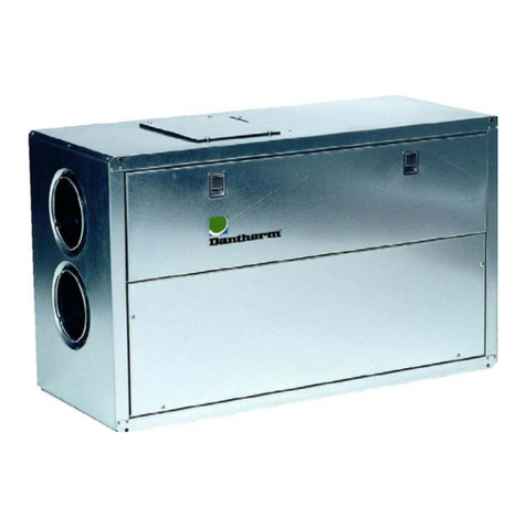
Dantherm HRV 5 User manual

Focus. Trust. Initiative.
HRV 5
Service manual
DA GB DE
No. 039994• rev. 2.0 • 08.03.2011

2005 layout

HRV 5
Service manual
EN
DA
DE
No. 039994• rev. 2.0 • 08.03.2011

Der tages forbehold for trykfejl og ændringer
Dantherm can accept no responsibility for possible errors and changes
Irrtümer und Änderungen vorbehalten
Dantherm n’assume aucune responsabilité pour erreurs et modifications éventuelles

3
039754 •Version 2.0 • 08.03.2011
EN
EN
EN
EN
EN
Introduction
Overview
Introduction
This is the service manual for the Dantherm Air Handling home ventilation unit HRV 5.
The table of contents below gives you an overview of the main sections. Please see the
complete table of contents for further information about the sections.
Table of contents
This service manual covers the following main topics:
Topic
See page
Table of contents, complete
Next page
General information
6
Product description
7
Functional description
13
Get ready for use
18
User’s guide
21
Service guide
32
Technical information
43
Appendix A –Performance, temperature efficiency and specific fan
performance
49
Appendix B –Start up and running information
50
Index
51

4
Table of contents
Introduction
This is the complete table of contents covering all sections in this service manual.
Each main section will begin with an introduction including a separate table of contents
covering the exact section.
Table of contents
This service manual covers the following topics:
Topic
See page
Introduction
3
Table of contents
4
General information
6
Product description
7
General description
8
Description of parts
9
Description of the control kit
11
Functional description
13
Setpoints
14
Functions
15
Get ready for use
18
Mounting and installation
19
User’s guide
21
How to use the remote controller
22
How to set the time
23
How to set temperature setpoints
24
How to set fan speed
25
How to set filter alarm settings
27
How to set programmes
28
How to read out information under the service menu
30
How to read out air temperaturess
31
Service guide
32
Preventive maintenance
33
How to replace filters and reset filter alarm
35
Accessories
37
Spare part list
39
Fault finding guide
40
Service agreement
42
Technical information
43
Technical data
44
Dimensions
45
Wiring diagram
46
Continued overleaf

6
General information
Introduction
This section gives you the general information about this service manual and about the unit.
Manual, part no.
Part number of this service manual is 039754.
Target group
The target group for this service manual are:
The daily users
Technicians who install and maintain the unit
Copyright
Copying of this service manual, or part of it, is forbidden without prior written permission
from Dantherm Air Handling A/S.
Reservations
Dantherm Air Handling A/S reserves the right to make changes and improvements to
the product and the service manual at any time without prior notice or obligation.
EU Declaration of
Conformity
Dantherm Air Handling A/S, Marienlystvej 65, DK-7800 Skive hereby declare that the
unit mentioned below:
026836 DVR 450
Is in conformity with the following directives:
98/37/EEC Directive on the safety of machines
73/23/EEC Low Voltage Directive
89/336/EEC EMC Directive
- and is manufactured in conformity with the following harmonized standards:
EN 292 Machine safety
EN 50 081-82 EMC
EN 60 335-1 Low Voltage
Skive, 26.01.2007
Recycling
The unit is designed to last for many years. When the time comes for the unit to be re-
cycled, the unit should be recycled according to national rules and procedures to pro-
tect the environment.

7
039754 •Version 2.0 • 08.03.2011
EN
EN
EN
EN
EN
Product description
Overview
Introduction
This section will give you a description of the HRV 5 and its functionality.
Contents
This section covers the following topics:
Topic
See page
General description
8
Description of parts
9
Description of the control kit
11

8
General description
Introduction
This section gives you a description of the unit as a whole. The following section de-
scribes the different parts in details.
Usage of HRV 5
HRV 5 is used for ventilation of private homes.
The unit supplies fresh outdoor air to the house.
Dirty and humid air is drawn out of the house and its heat is used for heating up the
fresh outdoor air before it is blown into the house.
Installation
The unit will most often be mounted in the utility room, a heated shed or the like in con-
nection with single-family houses or apartments.
Illustration, inter-
nal
This drawing illustrates the unit with its different parts, visible from the internal side:
Parts
This table gives an overview of the main parts of the unit:
No.
Part
No.
Part
Main control board
Filter (F7)
Electric heating element (accessory)
Extract air fan
Filter (G4)
Temperature sensors T1, T2, T3, T4
Heat exchanger
Safety switch
Supply air fan
-
-
Safety switch
For safety reasons the power supply is automatically cut off by the safety switch
when the front cover is removed.
When putting the front cover back into place, make sure that the four thumbscrews are
completely tightened. This activates the unit automatically.
The current time must be reset if the power has been cut off, see "How to set the time",
page 23.

9
039754 •Version 2.0 • 08.03.2011
EN
EN
EN
EN
EN
Description of parts
Introduction
This section will give you a more detailed description of the parts of DVR 450. See the
illustration in section “General description” on page 8.
The described parts are:
Cabinet
Electric heating element
(accessory)
Filters
Heat exchanger
Fans
Control kit
Temperature sensors
Cabinet
The cabinet is made of painted, hot galvanised sheet steel, which is insulated with a fire
retardant polyester foam. The foam is heat insulating and sound-absorbing.
Electric heating
element
(accessory)
The unit can be equipped with an electric heating element. The heating element is
placed inside the unit. It is protected with an overheat protection switch.
The electric heating element keeps the internal temperature at an adequate level at low
ambient temperatures. See the section ”User’s guide”, page 21 for setting of supply air
temperature.
Filters
The purpose of the filters is to protect the heat exchanger and to filter dust from the
outdoor air before it enters the house.
During the filter timer period of 3000 hours, the fan speed will increase to compensate
for filters getting more and more dirty. This will ensure a constant air change in spite of
the dirt. When the timer has 2500 hours left, the speed of each fan increases by 50
r.p.m. When 2000 hours are left, the speed increases by further 50 rotations, resulting
in a total increase of 300 r.p.m. of each fan when the timer is at 0.
The unit is standard equipped with filters class F7 cassette filter on supply air and G4
cassette filter on exhaust air.
Heat exchanger
The heat exchanger ensures that heat in the extract/return air is transferred to the sup-
ply air, when both air flows pass each other in the heat exchanger.
Fans
There are two fans in the unit. The purpose of the fans is described below.
Supply fan
The supply air fan draws fresh outdoor air through the unit and the heat exchanger and
supplies it with recovered heat to bedrooms, living rooms and possibly sauna or steam
bath.
Extract fan
The extract air fan draws air from the kitchen (in some cases the cooker hood), toilets,
baths, sauna and/or steam bath through the unit and heat exchanger where the heat is
recovered. Finally the air is exhausted to the outside.
Continued overleaf

10
Description of parts, continued
Control kit
The control kit is described in details in the section “Description of the control kit” page
11. For changing settings, see ”User’s guide”, page 21.
Temperature sen-
sors
The unit is equipped with four temperature sensors. The placement of each sensor is il-
lustrated in section “General description”, page 8.
Part
Function
T1
Outdoor air temperature
Gives information about the outdoor temperature
T2
Supply air temperature
For heating element. See more about heating in
“Functional description”, page 13
T3
Extract air temperature
Gives information about the temperature of the air
that is drawn into the unit from the house
T4
Exhaust air temperature
Gives information about the temperature of the air
that is exhausted to the outside.

11
039754 •Version 2.0 • 08.03.2011
EN
EN
EN
EN
EN
Description of the control kit
Introduction
This section gives you a detailed description of the control kit for HRV 5.
Function
The control kit consists of a main control board (PCB), an antenna and a remote con-
troller.
The main control board receives and sends information through the antenna to and
from the remote controller. In addition the main control board contains a number of ac-
cessories which are further described in the section ”Accessories” on page 37.
Illustration
This drawing illustrates the remote controller, the main control board and the antenna:
Remote controller
The remote controller is the control part of the control kit and it is described in more de-
tails in the following. The section ”User’s guide” on page 21 describes the setting of the
menus.
Symbols and
icons
This illustrates the different symbols and icons of the screen:
continued overleaf
Weekday
Fan speed
Display of data
(Normal display
shows the actual
time)
Clock
Menu icons
Temperature settings
Fan speed
Filter alarm
Programmes
Service
Heat (Here step 10 of 10).
Electric heating element
is an accessory
Screen with display
Keyboard
Information field

12
Description of the control kit, continued
Start up screen
This illustrates the start up screen or ”normal screen condition” (the example shows
that it is Wednesday, the time is 13:45, and the fan is running at step 1 speed):
Batteries
The remote controller uses two standard 1,5 V AAA batteries (included)
Activating
The remote controller is automatically activated by pressing any key.
Please note: After connecting the unit, it may take up to 2 minutes before the remote
controller shows the correct display
This will happen after each disconnection and reconnection of the unit
Power saving func-
tion
The remote controller switches automatically off after approx. 2 minutes without press-
ing any keys (Sleep function)
Faulty operation
/filter alarm
The remote controller is automatically activated for about 1 minute every two hours to
test for faulty operation or filter alarm.

13
039754 •Version 2.0 • 08.03.2011
EN
EN
EN
EN
EN
Functional description
Overview
Introduction
This section describes the functions of HRV 5.
Important
The ventilation system should operate continuously!
It is not advisable to stop the ventilation, even for longer holidays.
Function
The unit supplies fresh air, drawn in from the outside, to living rooms including sauna
and steam bath if present.
The dirty and humid air is drawn out from the kitchen, the living rooms, the baths etc.
and led into the unit, where the unit reuses the heat from the dirty air to warm up the
fresh outdoor air before this is blown into the house.
Contents
This section covers following topics:
Topic
See page
Setpoints
14
Functions
15

14
Setpoints
Introduction
This section gives you a description of the various setpoints for HRV 5. Information on
how to change the setpoints is described in the sections ”How to set temperature set-
points” page 24 and ”How to set fan speed” page. 25.
Factory setting
The factory settings are as follows:
Setpoint
Factory setting
Setting area
Temperature for
electric heating element,
Tmin
18 °C
12 –25 °C
Temperature for summer
operation, Tmax
24 °C
17 –30 °C
Fan speed, step 1
25 %
750 RPM
25-98 %
but it can never be higher
than step 2
Fan speed, step 2
50 %
1500 RPM
26-99 %
but it can never be lower
than step 1 nor higher than
step 3
Fan speed, step 3
70 %
2250 RPM
27-100 %
but it can never be lower
than step 2
Relation between extract
and supply
100 %
70 –130 %
But min/max = 750/3000
RPM per fan
Tmin
When the supply air temperature falls under the factory setting, the electric heating el-
ement (accessory) will switch on.
Tmax
When the extract air temperature rises above the factory setting, summer mode will be
switched on and the heat exchanger switches off.
Fan speeds
Standard setting for the relation between extract air and supply air is 100 %, which
means that the supply air fan is running at the same speed as the extract air fan. Set-
ting scale is from 70 % to 130 %, which means that the supply fan can be set to run
30 % slower or quicker than the extract fan. The function is used partly to compensate
for differences in the counter pressure in the supply air system compared to the extract
air system, partly to ensure a constant negative pressure in the house.

15
039754 •Version 2.0 • 08.03.2011
EN
EN
EN
EN
EN
Functions
Introduction
This section gives you a description of the various functions of HRV 5.
Summer operation
In the summer when the room air temperature is higher than the outside air and cooling
is required, it is not necessary to heat the outside air before it is blown into the house.
In summer mode the heat exchange between supply air and extract air is deactivated
by stopping the heat exchanger. Fresh outside air is then led into the house at un-
changed temperature.
The summer mode function automatically switches off the heat exchanger when the fol-
lowing three conditions are fulfilled at the same time:
No.
Condition
1
Outdoor air T1 is colder than the extract air T3
2
The extract air is warmer than the Tmax set point
3
Outdoor air temperature is higher than 14 °C (air used for cooling should not
be colder than that)
The summer mode function automatically switches on the heat exchanger when one of
the following three conditions is fulfilled:
No.
Condition
1
Outdoor air is warmer than the extract air+2
2
Extract air is colder than Tmax-2
3
Outdoor air is colder than 12 °C
The hysteresis of 2 degrees ensures that the heat exchanger does not start and stop
too frequently in the transition period.
See the section ”User’s guide”, page 21 for adjustment of summer mode settings and
how to change these settings.
Summer mode
screen
When the heat exchanger is stopped this will be indi-
cated by a by-pass symbol above the plant icon inside
the house icon. This symbolises that the air is by-
passing the heat exchanger.
Continued overleaf

16
Functions, continued
Electric heating el-
ement
(accessory)
The electric heating element switches on when the supply air temperature drops to a
temperature lower than the heater set point (factory setting = 18 °C). The electric heat-
ing element switches off when the temperature has rised to a temperature which is min-
imum 2 °C higher than the heater set point.
See ”User’s guide”, page 21 to change set points.
The electric heating element has 10 steps. The function of these steps is to keep the
electric heating element lit for 1 to 10 seconds during a period of 10 seconds. The
steps are controlled in accordance with the following function:
Every 60 second the control automatically checks the supply air temperature T2 as fol-
lows:
Condition
Action
If supply air temperature T2 is lower than Tmin
Increases by one heat step
If supply air temperature T2 is between Tmin and Tmin
+2
Remains on actual heat step
If supply air temperature T2 is higher than Tmin +2
Goes down one by one heat
step
Electric heating el-
ement display
The actual heat step is shown in right side of display.
Here 10 heat steps are displayed.
Programs
You can programme up to 20 different program sequences (from P01 to P20). For set-
ting of programs, see the section ”How to set programmes” page 28.
Illustration of air
flows
This illustrates the air flow of the HRV 5:
Continued overleaf

17
039754 •Version 2.0 • 08.03.2011
EN
EN
EN
EN
EN
Functions, continued
Air flow descrip-
tion
This describes the air flow in details:
No.
Description
1
Outdoor air
Fresh air entering the heat exchanger ready to be heated
by the extract air from the inside of the house (3)
2
(Heated) supply
air
Comfort air heated by the extract air from inside the house
(3)
3
Extract air
Old indoor air used to heat the incoming fresh outdoor air
(1)
4
Exhaust air
The heat has been drawn out of the old indoor air to warm
up the fresh outdoor air (1). The exhaust air is led out of the
house and the system
Filter guard
After approx. 3000 running hours, corresponding to approx. 4 months use, the filter
alarm function will activate a buzzer in the remote controller. See more about filter
maintenance in the section “Preventive maintenance”, page 33.
The timer has to be manually reset, see section ”User’s guide”, page 21.
Table of contents
Languages:
Other Dantherm Water Filtration System manuals
Popular Water Filtration System manuals by other brands

Wen
Wen AF1270 instruction manual

Blue Mountain
Blue Mountain RAIN HARVESTING WFRW13 installation guide

Marlo Incorporated
Marlo Incorporated AFC Series Installation, operation and maintenance manual

ADTRAN
ADTRAN Total Access Total Access 19-Inch Fan Filter Installation and maintenance practice

Waterite
Waterite Vectapure II RO-4042H Installation and owner's manual

ProMinent
ProMinent Dulcodes M operating instructions