DareGlobal DB120-WL User manual

DB120-WL
4Port Wireless ADSL2/2+Modem
UserManual
V1.0

DSLGateway/Router UserManual
Page2Total24Pages
CONTENTS
1. OVERVIEW...................................................................................................................................................... 3
1.1 ABOUT ADSL...................................................................................................................................... 3
1.2 ABOUT ADSL2/2+.............................................................................................................................. 3
1.3 FEATURES .......................................................................................................................................... 3
2 SPECIFICATION.............................................................................................................................................. 4
2.1 INTERFACE INTRODUCTION.......................................................................................................... 4
2.1.1 INDICATOR ANDINTERFACE.................................................................................................. 4
2.1.2 SPLITTERSPEC.......................................................................................................................... 4
2.2 HARDWARE CONNECTION............................................................................................................. 4
2.3 LED STATUS INDICATION................................................................................................................ 5
3. CONFIGURATION.......................................................................................................................................... 6
3.1 DEFAULT CONFIGURATION............................................................................................................ 6
3.2 COMPUTER CONFIGURATION....................................................................................................... 6
3.3 ADSL MODEM CONFIGURATION................................................................................................... 6
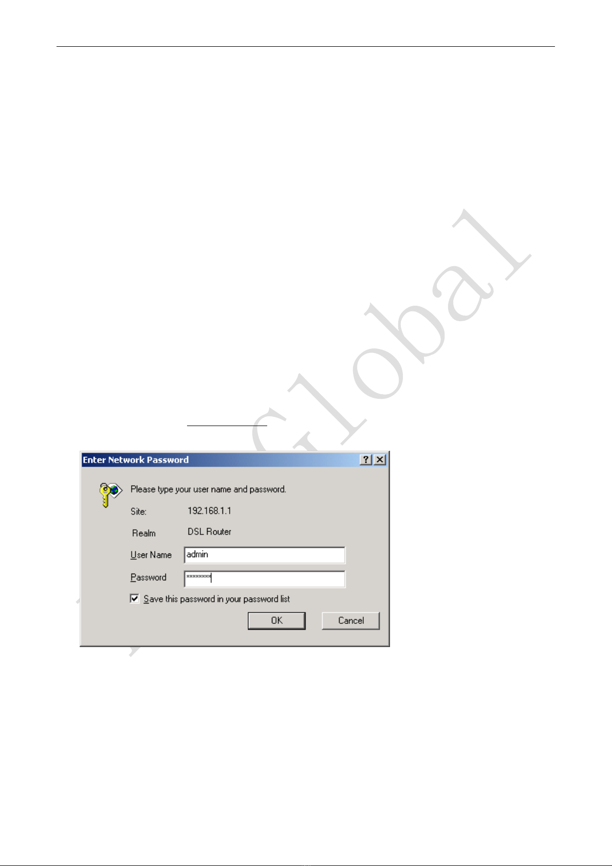
3.3.1 LOG IN.......................................................................................................................................... 6
3.3.2 SAVESETTING............................................................................................................................ 6
3.4 WAN CONFIGURATION .................................................................................................................... 7
3.4.1 VIewWANService ....................................................................................................................... 7
3.4.2 RFC1483 BRIDGEONATMCONFIGURATION....................................................................... 7
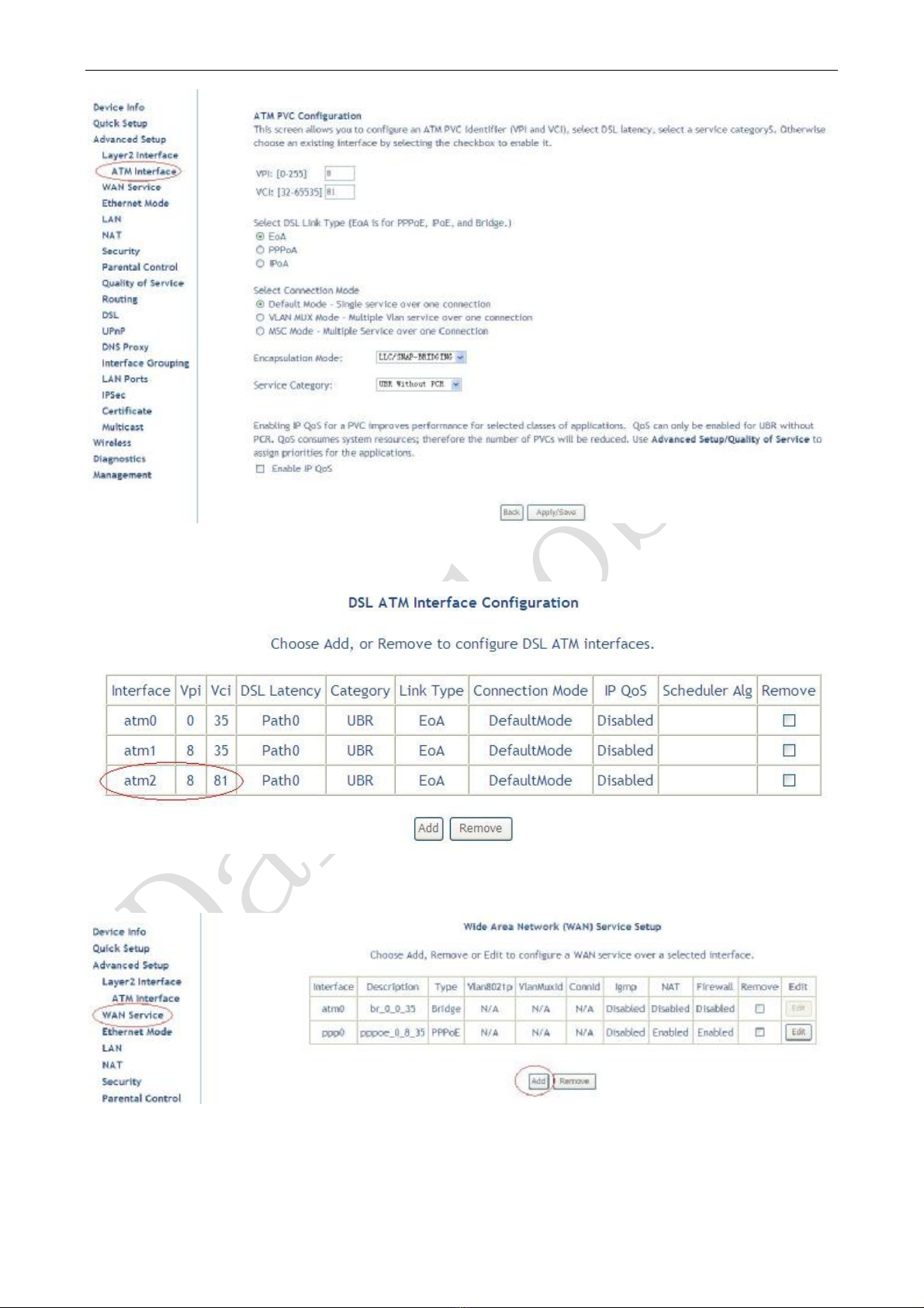
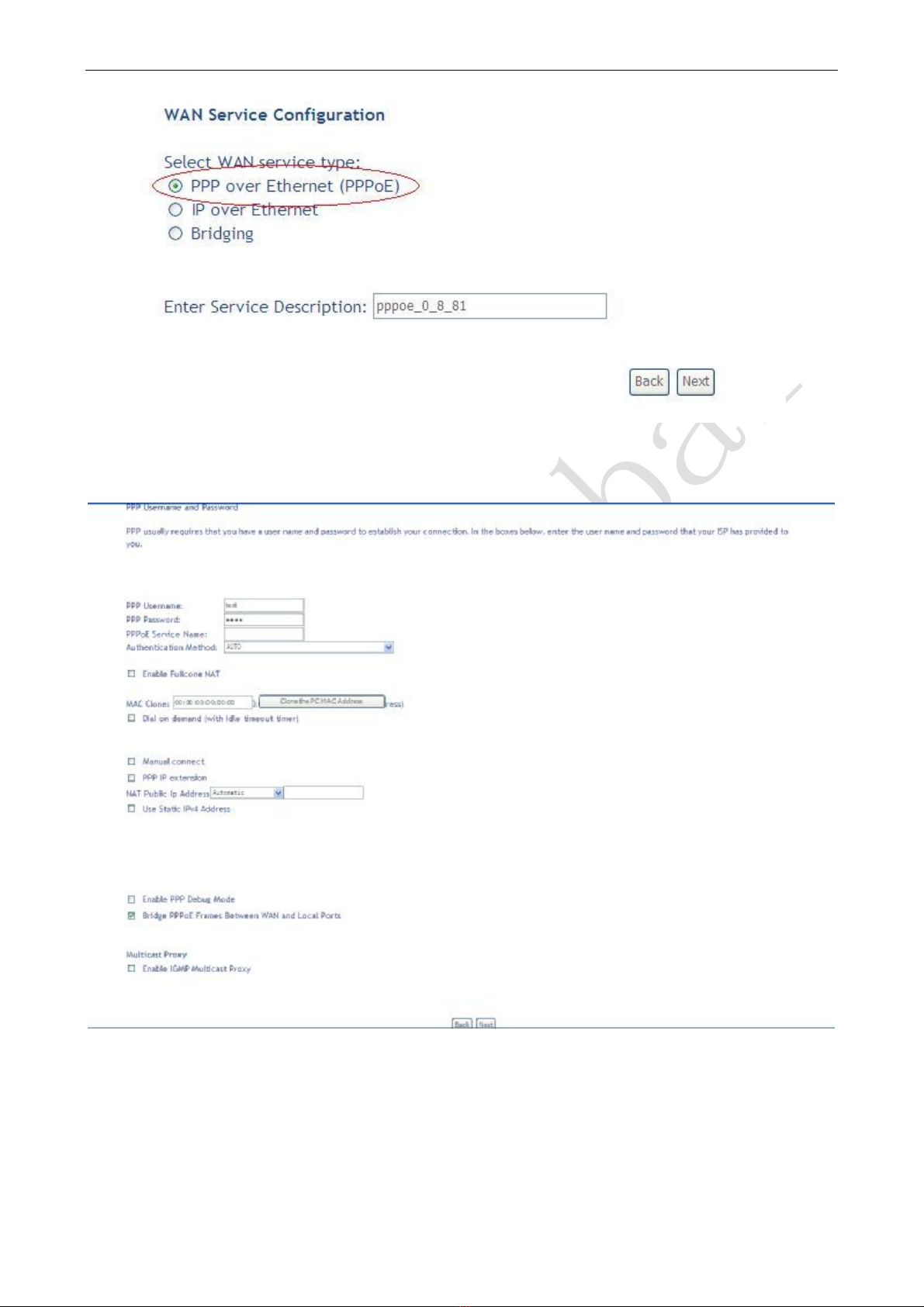
3.4.3 PPPOEONATMCONFIGURATION.......................................................................................... 9
3.4.4 IPOEON ATMCONFIGURATION ........................................................................................... 12
3.5 WIRELESS CONFIGURATION........................................................................................................ 15
3.5.1 WIRELESS BASICSETUP........................................................................................................ 16
3.5.2 WIRELESS SECURITY............................................................................................................. 16
3.5.3 WIRELESS MACFilter.............................................................................................................. 18
3.5.4 WIRELESS ADVANCEDSETUp.............................................................................................. 19
4 OTHER CONFIGURATION ......................................................................................................................... 19
4.1 LAN CONFIGURATION................................................................................................................... 19
4.1.1 Configuration ofModem’spassword.......................................................................................... 19
4.1.2 CONFIGURATION OFMODEM’S IPADDRESS.................................................................... 20
4.1.2 DHCPCONFIGURATION ......................................................................................................... 21
5. TROUBLESHOOTING................................................................................................................................. 21
5.1 UNABLE TO ACCESS INTERNET.................................................................................................. 21
5.1.1 CHECKTHELINEANDTHEDEVICE ................................................................................... 21
5.1.2 CHECKYOURCONFIGURATION .......................................................................................... 22
ANNEX SHIPPINGLIST............................................................................................................................... 23

DSLGateway/Router UserManual
Page3Total24Pages
1.OVERVIEW
1.1 ABOUTADSL
AnADSLMODEMisa broadband Internetaccess device, which utilizesthe high frequencysegmentof
the phone line to transmit high-speed data withoutaffecting the voice transmission. The frequencyofthe ADSL
signalishigherthan thatofvoice, so voice and ADSLsignalcan coexistin one line byusing a splitterto
insulate each fromthe other.ADSLdata transferadaptsthe asymmetrymodel.Itsupports upload transmission
speed up to1Mbpsand download speedup to 8 Mbps(24MbpsforADSL2+).ADSLisan idealdevice for
broadband access.
1.2ABOUTADSL2/2+
Transmission performance ofADSL2 isimproved comparing with the first generation ofADSL.These
improvementsare mainlyconcerned with long distance, anti-line-loss, anti-noise, etc. Bydoubling the
transmission bandwidth, ADSL2+hasimplemented a downlink rate ashigh as24 Mbps.Therefore, Internet
applicationssuch assynchronoustransmission ofmulti video stream, online gamesand huge capacityof
downloading filesare made possible.
1.3 FEATURES
1Support ANSIT1.413 ISSUE2, ITUG.992.1 (G.DMT), ITUG.992.2 (G.LITE), ITUG992.3, ITU
G992.5
2Web-based configuration and monitoring.
3Support multiple PVCs.
4Routing function including static routing and RIP
5DNS function ,includingDNS server, DNSRelay, DDNS
6NAPT,DHCP, Firewall, UPNPfunction.
7QualityofService ControlforTraffic Prioritization.
8Supports VirtualPrivate Network (VPN)pass-through.
9Support 802.11b, 802.11g.
10 Support Multiple SSID
11 Support Wireless MACFilter,Wireless Bridge, and WPS(Push-Button and PIN).
12 Diagnosticsfunction.
13 Support SNMP,TR069 and TR064 to manage the device.
14 Access Controlfunction.
15 Device LOG function
16 Update software viaWEB,CLI,TR069

DSLGateway/Router UserManual
Page4Total24Pages
2SPECIFICATION
2.1INTERFACEINTRODUCTION
2.1.1INDICATORAND INTERFACE
Table 2.1
ITEM Name State introduction
Indicator
POWER AsteadyGreen lightmeansthe powerconnection worksproperly
DSL Green, showDSLline status.
INTERNET Green, Flashing meansthe Modemistransmitting orreceiving data
WLAN Green, Indicatesstatusofconnection to the wireless device
Interface
LINE Connected with phone line or “ADSL”port ofthe splitter.
ETHERNET To beconnected to a PCnetwork card bya straight-through network cable, also
can use a crossovercable toconnecttoHub, Switch orRouter.
POWER Powerinterface, Connectwith poweradapter.
SWITCH To turn on /offthe power.
RESET Press theresetbutton and turn on the power, then keep pressing the resetbutton for
3 seconds.Then you can resetthe modemwith the default settings.
WIRELESS Open/Close wireless via pressing the button
2.1.2SPLITTERSPEC
Table 2.2
Interface Introduction
LINE Connected with telephone line
ADSL
Connectwith the LINEport ofthe
ADSLModemusing telephone
line provided.
PHONE Connectwith telephone
2.2HARDWARECONNECTION
Introduction:
1Use a telephone cord to connectthe LINEport ofthe splitterwith the RJ-11 port (the phone jack)on
the wall.
2Use anothertelephone cord to connectthe ADSLport ofthe splitterwith the LINEportofthe ADSL
Modem.
3Use anothertelephone cord to connectthe telephonesetwith the PHONEport ofthe splitter.
4ConnectEthernetport ofthe ADSLMODEMwith 10/100BASE-Tport ofthe computerusing the
network cable thatcomeswith the modem.
5Plug in the powercord, and turn on the power.
Ifyou do notwantInternetservicesand telephone voice servicessimultaneously, please justconnectthe
LINEport ofthe ADSLModemwith the RJ-11 port (the phone jack)on the wall using a telephonecord. In this
case, the splitterisnotnecessary.

DSLGateway/Router UserManual
Page5Total24Pages
2.3LEDSTATUSINDICATION
Table 2.3
Status POWER
(red)
DSL(green) INTERNET
(green)
WIRELESS(green)
Steady
light
PoweronThe modemisin good
connection
/ Wireless is
connected
Flashing
/ In handshaking status / /
Fast
flashing
/ / Transmitting or
receiving data
Transforming data
Off PoweroffConnection notsetup Notconnected
with PC
properly
Wireless is
disabled

DSLGateway/Router UserManual
Page6Total24Pages
3. CONFIGURATION
3.1DEFAULTCONFIGURATION
ADSLMODEMhaspre-configured with the VCI/VPIwhich isin common use.
3.2COMPUTERCONFIGURATION
The default IPaddressforADSLMODEMis: 192.168.1.1;The SubnetMask is:255.255.255.0.Users can
configureADSLMODEMthrough an Internetbrowser.ADSLMODEMcan be usedasgatewayand DNS
server; users need to setthe computer’sTCP/IPprotocolasfollow:
1Setthe computerIPaddress atsame segmentofADSLMODEM,such assetthe IPaddress ofthe
network card to one ofthe “192.168.1.2”~“192.168.1.254”.
2Setthe computer’sgatewaythe same IPaddress asthe ADSLModem’s.
3Setcomputer’sDNS serverthe same asADSLModem’sIPaddress orthatofan effective DNS server.
3.3ADSLMODEMCONFIGURATION
3.3.1LOG IN
Openthe browser; input http://192.168.1.1 atthe addresscolumn. Press “Enter”keythen the entrydialog
box will showup asFigure 3.1. InputUsername:admin, Password:admin (capitalsensitive), then press Enter.
Figure 3.1
3.3.2SAVE SETTING
Aftergetting through each page forparameters setting, click “Save”or “Save/Apply”to store the value in
ADSLMODEM. Briefly, we named “Save”.
Note

DSLGateway/Router UserManual
Page7Total24Pages
When you save the settings,the web page will be refreshed slowly,pleasewait it finished.
Some settingsonly take effectafterrebooting the router.
3.4WAN CONFIGURATION
Ifthe configuration isbridge encapsulation, there isno need to configureanymore parameters. Onlyneed
to use the third partydial-up software to connectthe Internet.
Totally, thisroutersupports:PPPoA,PPPoE, MER, IPoE, IPoA,Bridging. Fordetail configuration
information, please check the following configuration guide.
3.4.1VIEWWAN SERVICE
Click “Device Info”on the left page, and enterinto “WAN”page.
lNOTE:Atmost we can supporteightconnections.Wesupportedit non-bridge wan connections.
There isnoneed to rebootthe device when you add/remove/edit one wan connection. It takeseffect
immediately.
Figure 3.2
3.4.2RFC1483BRIDGE ONATMCONFIGURATION
Click “Advanced Setup”on the left page, and enterinto “Layer2Interface”configuration page, where we can
selectthe type ofLayer2-Interface ATM.
lNOTE:ATM interface isourmost commonly used mode, which will transportdata on DSLline via
Bridge orRouteConnections.
SelectATMInterface, then click “Add”button to add one NEWInterface ofLayer2.Then inputAppropriate
VPI/VCI, selectEOAused forIPoE, PPPoE, Bridge, and selectEncapsulation Mode and Service Category,
Connection Mode (Default,VLAN-MUX, MSC). IfQOS need,please select “EnablequalityService”. Usually,
you onlyneed to setup VPI/VCIto the value assigned byyourISP.Atlastclick “Apply/Save”button to save
the configuration.

DSLGateway/Router UserManual
Page8Total24Pages
Figure 3.3
Afteryoursave, there will be one Layer2Interface (atm2)added asfollowing:
Figure 3.4
Next, add one Layer3Interface via “Wan Service”configuration page, and click “add”button asfollowing:
Figure 3.5
You need to selectone Layer2 Interface fromthe Layer2Interface List.Then click “Next”to selectBridge
mode:

DSLGateway/Router UserManual
Page9Total24Pages
Figure 3.6
Press “Next”to enterinto “WANSetup -Summary”, click “Apply/Save”to save configuration, if you need to
modifythe parameter, click “Back”asFigure 3.7.
Figure 3.7
3.4.3PPPOE ON ATMCONFIGURATION
PPPoEisalso known asRFC2516. Itisa method ofencapsulating PPPpacketsoverEthernet.
PPPoAisalso known asRFC2364 andnamed asPeertoPeerProtocoloverATM.AsPPPoE, it also hasall
the featuresofPPP.Although it’sbased on ATMprotocol, the setting ofall the otherparameters issimilarwith
PPPoE. So we onlyintroduce PPPoEindetail here.
InFigure 3.6, selectPPP overEthernet(PPPoE)

DSLGateway/Router UserManual
Page10Total24Pages
Figure 3.8
Press “Next”entering the configuring interface, asFigure3.9.
Figure 3.9
lPPPUsername:YouraccountfromISPto access Internet.
lPPPPassword:Inputthe password assigned byyourISP.
lPPPoEService Name:Servername ofnetwork ISP. No need to set.
lAuthentication Method:Authentication mode ofnetworkISP. Default isAUTO.
lDialon demand:When thismode isselected, the connection thathasno traffic within assigned disconnect

DSLGateway/Router UserManual
Page11Total24Pages
timeout(e.g. 1 minute)will be automaticallydisconnected. The connection will be activated
again when traffic arrives.Thisfunction isadvantageousforusers who are charged with
online time. Itshould be noticed thatsome programsautomaticallylink toInternet. Computer
will send data to network when infected byvirus. Connection will notbe disconnectedunder
these data streams.
lInactivityTimeout:When “Dialon demand”isselected,thisinputbox indicatesthatafterhowlong the
connection will be disconnected in the absence oftraffic. Ifthe value is0, connection will not
be disconnected.
lEnable manualMTUset: setMTUvalue manuallybyyourself
lManualConnect: connect/disconnectPPPoEconnection manually
Press “Next”to selectdefaultgatewayfromRouting Interfaces:
Figure 3.10
Press “Next”to setup default DNS serverasfollowing:

DSLGateway/Router UserManual
Page12Total24Pages
Figure 3.11
Press “Next”to enterinto “WANSetup -Summary”, click “Apply/Save”to save configuration, if you need to
modifythe parameter, click “Back”asFigure 3.12
Figure 3.12
3.4.4IPOE ON ATMCONFIGURATION
InFigure3.6, selectMAC Encapsulation Routing (MER).

DSLGateway/Router UserManual
Page13Total24Pages
Figure 3.13
Press “Next”, andthe IPaddress can be queried fromyourISP, the result asFigure3.14.
Figure 3.14
Press “Next”to configureservicesofTranslation on thisconnection, asFigure 3.15:

DSLGateway/Router UserManual
Page14Total24Pages
Figure 3.15
Press “Next”to selectdefaultgatewayfromRouting InterfacesasFigure 3.16:
Figure 3.16
Press “Next”to setup default DNS serverasFigure 3.17:

DSLGateway/Router UserManual
Page15Total24Pages
Figure 3.17
Press “Next”to enterinto “WANSetup -Summary”, click “Apply/Save”to save configuration, if you need to
modifythe parameter, click “Back”asasFigure 3.18
Figure 3.18
3.5WIRELESS CONFIGURATION
Press “Wireless”on the top ofweb pagestoenterwireless section. You can selecttoconfigure wireless
setup, securityand management.

DSLGateway/Router UserManual
Page16Total24Pages
Figure 3.19
3.5.1WIRELESS BASIC SETUP
Click “Basic”on the left menu to setup basic wireless parameters.In default, check “EnableWireless”box
to launch wireless AP.
lSSID(Service SetIdentifier):The mobile users cannotaccess WLAN until setting their SSIDasthe same
value ofthe wireless ADSL.The SSIDvalue ofthe ADSLis “wireless”
lHide Access Point: Ifchecked, wireless station will no see SSIDofthe ADSL.
3.5.2WIRELESS SECURITY
Press “Security”on theleft menu to constructwireless security.You can selectto configureWEP
encryption, Shared, 802.1x, WPA, and WPA2 authentication.
lWEPEncryption
Select “Enabled”ofthe WEPencryption list.You can enterWEPencryption page.
Encryption Strength: Keylength:128bitsor64bits.
NetworkKey 1-4: Up tofourkeysthatare in formofhex digitalscould be set. Mobile users can’t
access the APif theyhaven’tsetthe same keyasAP.For64bitsand 128bitskeys,you should input10
and 26 hexadecimaldigitalsor5 and 13 ASCIIcharacters respectively. Everytwo digitalsshould be
comparted with others bya space character. Forexample: “7890ABCDEF”(hexadecimaldigitals) or
“QWERT”(ASCII characters) fora keylength of64bits.

DSLGateway/Router UserManual
Page17Total24Pages
Figure 3.20
l802.1x Authentication
Select “802.1x”to enter802.1x authentication page.
The 802.1xauthentication needsa Radiusserverin LAN.In thispage, you can inputRadiusserverIP
address, port numberandsecretkey.

DSLGateway/Router UserManual
Page18Total24Pages
Figure 3.21
3.5.3WIRELESS MACFILTER
In fact, the Access Listfunction isjustlike MAC address filtering and selected to permitorforbid access
ofwireless station with specified MACaddress.
Method:select “Allow”or “Deny”mode, and click “Add”button, and inputMACaddress which you
wantto allowordeny.
Figure 3.22
Notice:You only can selectone ofallowmode ordeny mode.

DSLGateway/Router UserManual
Page19Total24Pages
3.5.4WIRELESS ADVANCEDSETUP
Press “Advanced”on the leftmenu to constructwireless securityasFigure 3.23
Figure 3.23
4OTHERCONFIGURATION
4.1LAN CONFIGURATION
4.1.1CONFIGURATION OFMODEM’SPASSWORD
When you configureADSLMODEMthroughan Internetbrowser, the systemrequiresusername and
password to validate access permission. The factorysetsthe modemata default username of “admin”and the
password of “admin”.The username isunchanged.You can enterthe “password configuration”on
Configuration column to change the password.
Attention:pleaseremember thepassword after change, otherwiseyou will notbeableto
changeconfiguration aftersavingsetting asFigure 4.1

DSLGateway/Router UserManual
Page20Total24Pages
Figure 4.1
4.1.2CONFIGURATION OFMODEM’SIP ADDRESS
Asa network device, ADSLModemhasitsown IPaddress and MACaddress.The factorysetsthe
MODEM, ata default IPaddress of192.168.1.1 andsubnetmask of255.255.255.0.The usercanconfigure
these addressesthrough the “LAN”on “Configuration”like this:
Forexample, change IPaddress to “10.10.10.10”.Click ”LAN”, input “IPaddress”:10.10.10.10, then
“subnetmask”:255.255.255.0, the result isasFigure 4.1, press “Apply/Save”asFigure 4.2.
Figure 4.2
Table of contents
Other DareGlobal Modem manuals