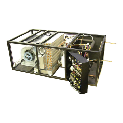
Data Aire DAC Series User manual

DATAAIRE SERIES
Operation and Maintenance Manual
Chilled Water 7-50 ton
INSTALLATION
OPERATION
MAINTENANCE

2
CONGRATULATIONS ON THE SELECTION OF A DATAAIRE PRECISION
ENVIRONMENTAL CONTROL SYSTEM. PROPER INSTALLATION, OPERATION
AND MAINTENANCE OF THIS EQUIPMENT WILL ENSURE YEARS OF OPTIMAL
PERFORMANCE.
This manual is intended to assist trained service personnel by providing
necessary guidelines for this particular equipment. Service to Data Aire units
should be done by qualified individuals with an adequate background in
areas such as HVAC, electrical, plumbing and electronics, as applicable.
Service performed by unauthorized or unqualified technicians may void
manufacturers’ warranties and could result in property damage and/or
personal injury.
Special care should be given to those area where these symbols appear.
Data Aire, Inc. reserves the right to make design changes for the purposes
of product improvement, or to withdraw any design without notice.

3
Table of Contents
1.0 INSTALLATION ................................................................................................... 5
1.1 Room Considerations........................................................................................... 5
1.2 Inspection............................................................................................................. 5
1.3 Rigging................................................................................................................. 5
1.4 Locating the Unit.................................................................................................. 6
1.4.1 Downflow Units .................................................................................................... 6
1.4.2 Upflow Units ......................................................................................................... 7
1.5 Paperwork ............................................................................................................ 7
1.6 Storage................................................................................................................. 7
2.0 PIPING ................................................................................................................. 8
2.1 Chilled Water Piping ............................................................................................ 8
2.1.1 Connection sizes, Chilled Water unit................................................................... 8
2.2 Chilled Water Valve Ratings ................................................................................ 8
2.2.1 3-Way Chilled Water Valves ................................................................................. 9
2.2.2 2-Way Chilled Water Valves ................................................................................. 9
2.3 Condensate Drain Piping..................................................................................... 9
2.4 Humidifier Piping................................................................................................ 10
2.4.1 Steam Generator Humidifier ............................................................................... 10
2.4.2 Dry Steam Humidifier.......................................................................................... 10
2.5 Leak Testing....................................................................................................... 10
3.0 ELECTRICAL CONNECTIONS ..........................................................................11
3.1 Electrical Service. . .............................................................................................11
3.2 Nameplate Ratings..............................................................................................11
3.3 Grounding ...........................................................................................................11
3.4 Voltage Tolerance ...............................................................................................11
3.5 Remote Shutdown...............................................................................................11
3.6 RemoteAlarm Contacts ......................................................................................11
3.7 Remote Sensors ................................................................................................ 12
3.8 Condensate Pumps............................................................................................ 12
3.9 Condensate Probe ............................................................................................. 12
3.10 Water Sensing Cable......................................................................................... 12
4.0 CONTROLS....................................................................................................... 13
4.1 DAPIII Microprocessor ControlPanel ................................................................. 13
4.2 Wiring Diagrams................................................................................................. 13
5.0 REGULAR MAINTENANCE ITEMS .................................................................. 14
5.1 Filters ................................................................................................................. 15
5.2 Belts ................................................................................................................... 14
5.3 Bearings............................................................................................................. 14

4
Table of Contents, cont’d
5.4 Humidifier Canisters ........................................................................................... 14
5.5 Fuses ................................................................................................................. 14
5.6 HeatingElements................................................................................................ 15
6.0 WARRANTY....................................................................................................... 16
7.0 CONTACT DATAAIRE ...................................................................................... 17
MONTHLY MAINTENANCE INSPECTION CHECKLIST ................................... 19
QUARTERLY MAINTENANCE INSPECTION CHECKLIST............................... 21
INDEX ................................................................................................................ 22

5
1.0 INSTALLATION
There is no intent on the part of DataAire, Inc. to define local codes or statutes which may
supercede common trade practices. The manufacturer assumes no responsibility for their
interpretation. Consult local building codes and the National Electrical Code for special
installation requirements.
1.1 Room Considerations
Precision air conditioning equipment is designed to control spaces within close tolerances
of temperature and humidity. However, the room must be built with a proper vapor barrier. Afilm of
polyethylene is often used on walls and ceilings. Walls and floors must also be painted with a
vapor-seal paint. Failure to provide a vapor barrier can compromise space conditions.
Introduction of outside air into the space should be minimized. Outside air in excess of 5% of
the total circulated air volume can have a significant effect on the overall space conditions and
result in poor space control.
1.2 Inspection
This Data Aire unit has been factory run-tested and has gone through a comprehensive
inspectionprior to itspackagingandshipment to ensurethatit arrives inexcellentcondition. However,
shipping damage can occur and a visual inspection of the outer crating immediately upon delivery
should be performed.
Noteany externaldamageor other transportationdamageonthe freightcarrier’sforms. Inspect
the unit itself for internal damage. Aclaim should be filed with the shipping company if the equipment
is damaged or incomplete.
Loose items such as remote control panels, disconnect switch handles, spare belts and spare
filters are packed inside the unit. Refer to the yellow shipping tag located on the unit door for
details.
Freight damage claims are the responsibility of the purchaser. Action to recover losses
should be filed immediately. Please notify factory personnel of any claims.
1.3 Rigging
Move the unit in its upright position to the installation site. It is recommended that the unit be
protected from damage to the decorative doors during any storage or moving. Removal of the
decorative doors is easily accomplished and may be done when moving equipment.
The shipping skid should be left in place if the unit is being moved with a forklift. If the unit is
being lifted, use spreader bars to prevent damage to the doors and panels.
The unit has 3/4" holes in the shipping skid to which casters with 3/4" stems can be attached.
This allows easy movement down halls, into elevators and through doorways. If clearance is a

6
problem the casters may be inserted directly into the bottom of the 1" tubular steel corner posts at
the bottom of the unit.
Warning: Improper lifting or moving of equipment may result in damage to decorative
doors, panels or frame members.
1.4 Locating the Unit
When installing the unit, sufficient space must be allowed for airflow clearance, wiring,
plumbing, and service access. It is recommended that each side and front have a clearance of at
least 30" to allow the doors to swing open and for servicing the unit.
The doors on some sides may not require as much service clearance. Refer to the particular
unit component breakdown drawings for assistance. Rear clearance is not required, but 1" to 2" of
clearance is suggested.
For the best air distribution, the unit should be centered against the longest wall, as close to
the heat load as possible, unless the unit is ducted. The unit should not be placed near any corner
of the room or at the end of a long, narrow room. Multiple units should be evenly spaced, as far
apart as possible.
Note to Installing Contractor: Condensation formation and frequent humidifier flushing
are normal functions of this equipment. Proper drain connections must be made to ensure
proper removal. Unit will require water connections for condensate removal and possibly
for humidifier makeup water, chilled water and/or hot water. Installation of units above
equipment that could sustain water damage should be avoided.
1.4.1 Downflow Units
Downflow units will typically sit on an elevated flooring system known as a raised floor. The
unit discharges air downward which pressurizes the raised floor and channels upward through
perforated floor tiles. Location and quantity of perforated tiles will dictate proper air distribution. If
the raised floor is strong enough to support the unit and local codes permit, the unit can be placed
directly on top with cutouts made for the discharge openings.
There may be additional support required in the form of adjustable jackstands. These are
adjustable, threaded leveling rods which support the unit in each of the corners and in the center on
longer length units. Tighten the locknuts provided with each jackstand. The baseplate can rest on
the floor or on vibration isolation pads.
Floorstands are also a way of supporting the unit. These are ordered to the height of the floor
with leveling rods to allow adjustment. The floorstand has lips in each corner to align with the unit
which is placed on top. It is recommended that the unit frame be bolted or screwed to the floorstand
from below. Local building codes may dictate this procedure. After installation, the raised floor is
typically built around the unit.
The raised floor serves as the distribution plenum for air on downflow units. Cables,
piping,wiring raceways, inadequate floor heightandany other restrictions can inhibitproper
airflow. Care should be taken to avoid restrictions.

7
1.4.2 Upflow Units
Upflow units will typically be supported by vibration isolation pads and/or floorstands which
and may also include leveling screws. An air discharge plenum may be factory provided which
ships loose and must be attached at the top of the unit frame.
Alternately, an air distribution plenum must be field fabricated with supply grilles to distribute
the air. Units are shipped with a drive package to overcome external static pressure. Adjustments
to the blower speed may be required to adjust to actual conditions.
1.5 Paperwork
Each Data Aire unit ships with a start-up sheet that should be completed during installation.
Also included in the paperwork is a warranty/information packet that provides important wiring
diagrams, specific component literature, warranty registrations cards and other valuable paperwork,
including a copy of this Installation/Operation and Maintenance manual.
A yellow tag is attached to the outside decorative door to indicate articles that may have
been packaged and shipped loose within the unit cabinet. Typically this would be jackstands,
condensate pumps and other loose components that are not factory mounted.
1.6 Storage
Your DataAire equipment comes ready for immediate installation. In some instances in may
be necessary to store the equipment for a period of time. If you must store the equipment it should
be done in a dry area, out of the weather, protected from damage by other equipment in storage or
transportation equipment, never stacked, and avoid frequent relocation.
If equipment is stored for longer than 30 days special precautions must be taken to avoid coil
damage. All coils should be charged and sealed with a low pressure (1-25 psig) inert gas, such as
nitrogen. This prevents contaminates from entering the coils; then when the seal is broken at
installation, the rush of escaping gas verifies the coil is still leak free. If coils are not charged and
sealed condensation mixes with air pollutants forming a weak acid and over time can cause pin hole
leaks to develop in the coil tubes.
When equipment is installed after storage caution should be taken to inspect and replace, if
required, rubber hoses and belts. All moving parts, such as blowers and motors, should be hand
tested to ensure that they are free and clear prior to start-up. Finally, verify that all lubrication is
fresh and full.
It is the responsibility of the installing contractor to return the start-up sheet and warranty
registration card to Data Aire for proper activation of the unit warranty. Failure to do so
may cause delays and in some cases void the warranty.

8
2.0 PIPING
2.1 Chilled Water Unit Piping
The required field installed water pipe sizes may or may not be the same as the connection
sizesattheunit. Thiswill depend on the length of pipe and the calculated pressure drop of peripheral
components.
Shutoff valves should be installed within a few feet of the inlet and outlet connections of the
unit to allow the unit to be isolated for service. Afill valve with a hose bib connection should also be
used on the supply line or return line at the unit to allow the unit to be drained.
Water temperature and worst-case room temperature and humidity conditions should be
used to determine whether external piping should be insulated. Typical water temperature is 45° F
which is usually cold enough to cause pipes to sweat.
Field pipe connections are topically made at the bottom of the unit. Punching holes in the
back panel and making a 90° turn out the back of the unit is also acceptable. In some cases
provisions have been made to route the pipes out the right or left side or out the top of the unit.
Openings should not be made in the hinged decorative doors as this could prevent the door from
swinging open.
Standard chilled water units have a 3-way chilled water valve. An option for a 2-way valve is
also available. In either case the water connections to the unit should be made so there is a
counterflow between the water and air. Field water pipe connections are labelled but the counterflow
should also be verified before making field connections.
One of the most common problems in a Chilled Water system is the presence of air in the
chilled water water loop. Air vents must be installed in various locations in the piping system to
purge the air.
2.1.1 Connection sizes, Chilled Water units
Water In and Out Water In and Out
Evaporator Model Connections, OD Evaporator Model Connections, OD
DACx 07 1 1/8” DACx 22 2 1/8”
DACx 09 1 1/8” DACx 26 2 1/8”
DACx 11 1 5/8” DACx 30 2 1/8”
DACx 13 1 5/8” DACx 40 2 5/8”
DACx 15 1 5/8” DACx 45 2 5/8”
DACx 18 2 1/8” DACx 50 2 5/8”
2.2 Chilled Water Valve Ratings
All chilled water valves used on DataAire Series models 7 to 50 tons use chilled water valves
that are rated at 400 psi operating pressure. The chart on the next page gives the valve size and Cv
rating on 3-way valves for all unit models. The same information plus maximum close off pressure
for optional 2-way valves is also indicated

9
2.2.1 3-Way Chilled Water Valves
Unit Model Valve Size Valve CV
DACx 07 1” 10.0
DACx 09 1” 10.0
DACx 11 1-1/4” 10.0
DACx 13 1-1/2” 19.0
DACx 15 1-1/2” 19.0
DACx 18 2” 46.0
DACx 22 2” 46.0
DACx 26 2” 46.0
DACx 30 2” 46.0
DACx 40 2” 46.0
DACx 45 2” 46.0
DACx 50 2” 46.0
2.2.2 2-Way Chilled Water Valves Close-off
Unit Model Valve Size Valve CV Pressure, psi
DACx 07 1” 10.0 200
DACx 09 1” 10.0 200
DACx 11 1 1/4” 10.0 200
DAC x 13 1 1/2” 19.0 200
DACx 15 1 1/2” 19.0 200
DACx 18 2” 46.0 200
DACx 22 2” 46.0 200
DACx 26 2” 46.0 200
DACx 30 2” 46.0 200
DACx 40 2” 46.0 200
DACx 45 2” 46.0 200
DACx 50 2” 46.0 200
2.3 Condensate Drain Piping
Every indoor unit has a 3/4" copper stub provided for condensate removal. A union is
recommended at the field connection which will permit easy disconnection from the unit for cleaning.
A trap should be built into the drain line to prevent air from backing up into the unit. Drain
lines should be pitched downward not less than 1/4" for each ten feet of horizontal run. Do not
reduce the size of the drain line.
Some applications have no convenient means of allowing a gravity drain. In this case, a
condensate pump can be used. These come either factory mounted or shipped loose. Factory
mounted condensate pumps do not require a separate power source.
Condensate pumps shipped loose (or field provided) typically require a dedicated 110 volt power
source. Field pipe connections must be made to the pump discharge connection. A check valve
must be installed to prevent short cycling. See also condensate pump electrical requirements in
Section 3.9.

10
2.4 Humidifier Piping
2.4.1 Steam Generator Humidifier
Thestandardhumidifier on DataAiresystemsisa steam generatortypewith a disposablecylinder.
Thehumidifier makeup water shouldbebrought to the humidifierthroughthe field connection opening
using 1/4" copper tubing. A compression fitting is provided at the humidifier.
A shutoff valve should be provided outside the air conditioner to allow disconnection for service.
An in-line water pressure regulator and strainer should be installed. Water pressure should be set
between 20 and 50 PSI.
The humidifier has a drain at the bottom which is factory piped to the main condensate drain line.
The dispersion tube also has a drain line. No additional field piping is required.
2.4.2 Dry Steam Humidifier
The optional dry steam type humidifier requires a strainer on the inlet steam line. An outlet
connection with a field-provided steam trap is also required. Steam pressure is typically 10-15 psi.
2.5 Leak Testing
No installation is complete until the entire system has been thoroughly checked for leaks. This
includes water lines, flare fittings, pressure controls, and Shrader fittings.
Check all humidifier water makeup lines, condensate lines, condensate pumps, chilled water
lines.
Tightening of fittings and valves is the responsibility of the installing contractor.

11
3.0 ELECTRICALCONNECTIONS
Beforeproceedingwiththeelectricalconnections,makecertainthatthevolts,hertz,andphase
correspondto that specified on theunitelectrical nameplate. Use copper conductors only.
3.1 Electrical Service
Checktobesurethe serviceprovided bythe utilityis sufficientto handlethe additionalload imposed
bythis equipment.
3.2 Nameplate Ratings
Refertotheunitelectricalnameplateforequipmentelectricalrequirements. Minimumcircuitampacity,
(MCA) also known as wire sizing amps, will dictate the minimum required wire gauge. Maximum
overcurrentprotection (MOP) device amps willdictatethe maximum circuit breaker orfusesize.
3.3 Grounding
Theunitcabinetmusthaveanuninterruptedtrueearthground. Anelectricalgroundwireofadequate
sizemust be connected to the groundlugprovidedinside the main electrical box.
3.4 Voltage Tolerance
The supply voltage to the unit must be within 10% of the voltage indicated on the unit electrical
nameplate. Phase to phase imbalance must not exceed 3%. The local utility company should be
contactedfor correction of improper line voltage. Deviationfromvoltageratings can cause premature
failuresand possibly voidunitwarranties.
Check the wiring connections in the unit control panel to ensure they are tight. Screw
terminalsmaybecomelooseintransit. Tighteningofwiringconnectionsistheresponsibility
oftheinstallingcontractor.
3.5 Remote Shutdown
Every Data Aire chilled water unit has remote shutdown contacts. These are intended for a field
supplieddry contactorswitch to bewiredacross two terminals. Whenthecontact orswitchopens, the
control circuit power is interrupted and the unit shuts down, including the control panel. The control
circuit is 24 VAC and the field provided contact or switch should have a minimum rating of 10 amps.
The remote shutdown contacts are always terminals #1 and #2 on the terminal block designated
TB1. Theunit will ship with afactory wired metal jumper clip thatconnects terminal #1 to terminal #2.
Removethis clip prior to installing the field wires.
3.6 Remote Alarm Contacts
TheDAPIII,microprocessor control panel providesaremotealarm output contact that can befield
accessed on terminals #11 and #13 of terminal block TB1. This is a Normally Open, Close onAlarm,
dry contact, intended to be used in a control circuit not exceeding 5 amps at 24 VAC.
This programmable output contact will close on a failure and remain closed until the alarm is no
longerpresent. Threeadditionalalarmoutputcontactscomewiththeoptionalrelaymodule. Theterminal
designations for these alarm output contact pairs are #40 and #42; #43 and #45; and #48 and #50.

12
3.7 Remote Sensors
Remotesensorsare optional. Although existing unit mounted sensors can be removed for remote
mounting, the remote sensor option provides a more convenient means of field installation. This is
becausethesensorsare alreadyconnected toapredeterminedlengthof cableand comemountedin a
remote sensor enclosure. The temperature and humidity sensors require a total of five wires, these
shouldbe a twisted, shielded cable.
3.8 Condensate Pumps
Condensatepumps which ship loosenormallyrequirea separatesource of 110volt power. Always
check the pump power requirements before connecting power. Condensate pumps are available in
othervoltages.
Condensatepumpsmayalsocomeunitmountedandpowered. Whilenooutsidepowersourceis
required,fieldpipingisstillarequirement.
Condensatepumps arewired to displaya “HighCondensateWaterLevel” alarm. Thewiringfor this
mustbe done in the field on pumps that shiploose. Factorymountedpumpscomepre-wired.
3.9 Condensate Probe
A condensate probe for sensing underfloor water is included with this unit. This comes in a plastic
bag,with about 15 feet ofcoiled-upwire. The probe is a flatplatethatis typically placed below theunit
ina location where waterislikelyto accumulate.
Placetheprobeflatontheflooron topof athin layerof nonconductivesilicone. Secure theattached
wireswhere necessary. Alonger length ofwiremaybeused if required.
Note: Failure to uncoil the length of wire attached to the condensate probe can result in a
nuisancewater-detectedalarm. Iftheprobeisnotgoingtobeuseditshouldbedisconnected.
3.10 Water Sensing Cable
Anotheroption for watersensingis the WaterDetection Cable. This is alongcable that can sense
moisture anywhere along its length. It is typically placed below the unit in a rectangular pattern that
matchesthe perimeterofthe unit.

13
4.0 CONTROLS
4.1 DAP III Microprocessor Control Panel
Thestandardcontrolson allDataAireSeriesequipmentistheDAPIIImicroprocessorcontrolpanel.
This state-of-the-art control panel has a separate manual that goes into extensive detail regarding
functions,features,programming,andtroubleshooting.
The DAP III microprocessor control panel has an entire manual dedicated to its use and
operation. Thismanualmustbereferencedtocompleteathoroughunitinstallation. Start-
upis not complete until theDAPIII controlpanel settings areestablished.
4.2 Wiring Diagrams
Every DataAire unit comes with a wiring diagram. These diagrams are ‘ladder’- type schematics
intended for service personnel. The intent is to allow the technician to understand the wiring details
associated withthe electricalcomponents and howthey interfacewiththe DAP IIIcontrol panelaswell
asperipheral equipment.
DataAire’schilled water unitwiringdiagrams will have a drawing number whichstartsoutwith the
three letter designation, “DAC”. An example of a typical diagram, DAC-S-813, is shown on page 18.

14
5.0 REGULARMAINTENANCEITEMS
5.1 Filters
Filtersshould bechecked onaregular basisand changedwhenthey becomedirty. Thiswill ensure
efficientoperationofthe unit. Althoughthe unithas adirtyfilteralarm,thisshouldnot berelied onas the
only determinant for replacing filters. Amaladjusted filter differential pressure switch may not give a
proper indication of a clogged filter.
Tocheckthefilterdifferentialpressure switchfor properadjustment,temporarilycoverabout 75%of
thereturnairopeningusingheavy cardboardor similarmaterial. The alarmshould energizewhen75%
ofthe air is blocked, simulating dirty filters. If the alarm energizesprematurelyordoesnot energize at
all,thepressureswitchshouldbeadjusted. Doorsmustremainclosedwhendeterminingifanadjustment
isnecessary.
Spare filters should be kept in stock as these tend to be a frequently replaced maintenance item.
Filtersmay requirechangingas oftenasmonthly. Notealsothatconstruction dust onnewinstallations
willquickly clognew filters.
Filters that require changing can restrict airflow and create problems such as poor air
distribution.
5.2 Belts
Belttensionshouldbecheckedregularly(monthly)toensurepropertension. Iftighteningisrequired,
loosen the four motor mounting bolts. Turn the adjustment screw on the end of the motor mounting
channeluntil the proper belt tension is attained. Retighten the four mounting bolts. Damage can also
occurto belts that areovertightened. Theamountof play in a typicaldriveset should be 1/2 inch.
5.3 Bearings
Pillowblock bearings used on many models havezirktype grease fittings. These will only require
grease once annually. Care should be taken to avoid over-greasing. Only one or two pumps from a
manual gun are required. All other blower bearings are permanently lubricated and do not require
maintenance.
Mostblower motors have sealed bearingsandaremaintenance free. Some motors have zirktype
greasefittingsonthe bearings. Ifsothemotorshould begreasedonceannually. Careshouldbe taken
toavoid over-greasing. Only one ortwopumpsfrom a manual gun arerequired.
5.4 Humidifier Canisters
SteamgeneratortypehumidifierisstandardonDataAireSeriesequipment. Thereisnomaintenance
requiredother thanto replacethecanister asrequired. Thisfrequency willdependon usageand water
type. A set of manufacturer’s instructions for the humidifier is sent as part of the paperwork placed
insidethe unit whenitships.
5.5 Fuses
Fuses may occasionally require changing especially with installations where the voltage is not
consistent. Drops involtagecancreatebriefperiods of high amp draw, causing fuses toblow. Always
replacefuseswiththoseoftheequivalentratingwithregardto: 1)amperage, 2)voltage,and 3)speed.

15
Forinstance motorsare inductiveloadswhich requiretimedelay fuses. Electricreheatand humidifiers
areresistiveloads requiring fast acting fuses.
5.6 Heating Elements
Heatingelementsdonotnormallyrequiremaintenance. Howeversometimesthey mayaccumulate
afilmofdustordirtwhenunused forextended periodsof time. Whenenergized, theburning debriscan
createsmokeorunpleasantodor. Tohelp avoid this, periodic cleaning is recommended.

16
6.0 WarrantyPolicy
Seller warrants its equipment to Buyer to be free from defects in material and workmanship for a
period of eighteen (18) months from date of shipment, as long as equipment is utilized under normal
conditionsand service andisproperly installed;however,thewarranty shall notbeapplicable toanyof
thefollowingitems:refrigerant,belts,filters,humidifier, heaters not regularly cleaned, light bulbs, and
anyother itemseitherconsumed orwornout bynormalwear andtear, orbyconditions beyondSeller’s
control,including (withoutlimitationastogenerally) polluted orcontaminatedairor water.
The Seller’s obligation under this warranty is limited solely to the repair or replacement, at Seller’s
options,ofanypartorparts thereofwhichshall, withineighteen(18)monthsfromdateofshipment ofthe
equipment to the original purchaser be returned to the factory, transportation charges prepaid, which
upon examination shall disclose to the Seller’s satisfaction to have been defective under normal use
andservice.Thisagreementtorepairorreplacedefectivepartsisexpresslyinlieuofallotherwarranties,
expressedorimpliedandallotherobligationsorliabilitiesonthepartofSellerandSellerneitherassumes
norauthorizesanyother personto assumeforit anyliability orobligationin connectionwith thesalesor
serviceofitsequipment,except said repair or replacement of defective parts set forth above.
Thiswarranty does not include any labor charges forworkdoneoutsideofthefactoryfor replacement
of parts, adjustments, repairs, or any other work. Seller’s liability does not include any resulting
damage to persons, property, equipment, goods or merchandise arising out of any defect in or
failure of any equipment of its manufacture and Buyer hereby waives any claim against Seller arising
out of such claim. This warranty shall not cover the repair or replacement of any equipment which
hasbeen repairedor alteredoutsideofthe factory inanyway or whichhasbeen subject tonegligence,
misuse, or abuse, or to pressures in excess of stated limits.
This warranty applies only to the original purchaser of the equipment and does not extend, expressly
or by implication, to the third parties or others without the specific written approval and
acknowledgment of Seller. Buyer’s exclusive remedy and Seller’s maximum liability for any and all
loss, injury, damage, costs, or expense arising from any defect covered by this warranty shall be
limited to the repair or replacement, but not the installation of any defective material, F.O.B., Seller’s
plant; provided however, that Seller shall not be required to replace any part or component (a) which
can be repaired, or (b) unless Buyer has given Seller immediate written notice that replacement or
repair.Inaddition, Seller shallnotbe liable for anycostor expense of replacementorrepaircontracted
for by Buyer with any third person, unless, and then only to the extent that Seller authorizes in
writing, such costs or expense.
Seller shall not be liable for any direct, indirect incidental, consequential, or other form of loss,
injury,damage,cost, orexpense,whethercausedbydelay,failure,orperformance,breach ofwarranty,
or by any cause whatsoever.
Seller’s obligation under this warranty shall be void if Buyer fails: (a) without legal justification to pay
Seller, when due, the full purchase price for the equipment sold hereunder; or (b) to have the
equipment sold hereunder installed, maintained, and serviced by competent personnel and in
accordance with Seller’s instructions.

17
7.0 Contact Data Aire
Address:Data Aire Inc.
230 W. BlueRidge Avenue
Orange, CA 92865
Phone 714-921-6000
800-347-AIRE (2473) Toll Free
Fax: 714-921-6010 Main
714-921-6011 Engineering
714-921-6022 Part Sales
E-mail:[email protected] Service
[email protected] TechnicalSupport
[email protected] Engineering
[email protected] Sales
Web site:www.dataaire.com
Job information:
Model Number: DA__ __ - __ __ __ __ - __ __
Serial Number: __ __ __ __ - __ __ __ __ - __
Job number: _______________________________________
Date installed: ___ / ___ / 20____
Installing Contractor: ________________________________

18

19
Data Aire, Inc.
Monthly Maintenance Inspection Checklist
Model No. _________________ Serial No. ____________________
Preparedby: _______________ Date: ___ / ___/ 20___
AirFilters
___ Check for restricted air flow
Blower Section
___ Blower wheel free of debris moves freely
___ Check belt tension and condition
___ Bearings in good condition
___ Check pulleys and motor mounts
Air Distribution Section
___ Check for restriction in grille(s)
Condensate Drain and Pump (if applicable)
___ Check for water leaks
___ Check for restricted air flow
___ Pump operation
Steam Generating Humidifier
___ Checkcanister fordepositsand waterlevel
___ Checkcondition ofsteam hoseandclamps
Infrared Humidifier (if applicable)
___ Check humidifier lamps
___ Check pan for mineral deposits
Electrical Panel
___ Check contactor operation
___ DAPIIIcontrolpanel operations
Equipment Runtimes
Blower _________ hrs
Reheat No. 1 _________ hrs
Reheat No. 2 _________ hrs
Reheat No. 3 _________ hrs
Humidifier _________ hrs
Dehumidification _________ hrs
Chilled Water Cooling _________ hrs
__ Reset all to read zero runtimes
Temperature/Humidity set at: ___° ___% RH
Notes: ________________________________________________________________________
_____________________________________________________________________________
_____________________________________________________________________________
_____________________________________________________________________________
_____________________________________________________________________________
_____________________________________________________________________________
_____________________________________________________________________________
_____________________________________________________________________________
_____________________________________________________________________________
_____________________________________________________________________________

20
Table of contents
Other Data Aire Chiller manuals
Popular Chiller manuals by other brands
Ocean Breeze
Ocean Breeze Micro Series instructions

Zanussi
Zanussi ZANUSSI easyChill 110043 Brochure & specs

Liebert
Liebert CBH 025 Service manual

Accu
Accu EQ Series Installation, operation and maintenance manual
Daikin
Daikin REYQ-AATJA Service manual
Arctica
Arctica HEF967 Installation, operation & maintenance manual
