1
Unit Installation
1.Installation Guides
WARNING!
①Installation should be performed by GREE appointed servicemen, or improper installation would lead to
unusual operation, water leakage, electric shock or re hazard.
②The unit should be installed on the foundation which is capable of supporting the unit, or the unit would fall
off or even lead to personal injury.
③All electric installation should be done by electrician in accordance with local laws and regulations, as
well as the User’s Manual and this Service Manual. Besides, the special power lines should be used, as any
improper line would lead to electric shock or re hazard.
④All electric lines should be safe and secured reliably. Be sure the terminal board and electric lines will not
be affected by any external force, or it would lead to re hazard.
⑤The electric lines should run properly to make the cover of the electric box secured tightly, or it would
cause the terminal board overheated or cause electric shock or re hazard.
⑥Cut off the power supply before touching any electric element.
CAUTION!
①The unit should be grounded properly and the ground line is not allowed to connect with the gas line,
water line, lightning rod or phone line.
②The breaker should be installed, or it would lead to electric shock.
③The drain pipe should be installed in accordance with the User’s Manual and this Service Manual to
ensure free drainage, and the drain pipe should be insulated against condensation. Once the drain pipe is
installed improperly, it would lead to water leak which then will damps the ceiling and furniture.
④Do not place the unit where there is oil fog, like kitchen, or the plastic would be aged, broken off or the
polluted evaporator would lead to water leak and poor performance.
⑤Do not place the unit where there is corrosive gas (like sulfur dioxide), or the corroded copper tubes or
welded joint would lead to refrigerant leakage.
⑥ Do not place the unit where there is inammable gas, carbon ber, inammable dust or volatile
combustible, as they would lead to re hazard.
SAFETY!
① Always use safety outts at the construction site.
②No smoking and no drunken operation are allowed at the construction site.
③Wear no gloves and tighten the cuff when operating the machinery and electrical equipment. Do not
maintain it during operation.
④Use the abrasive-disk cutter and stand at the side of the rotating abrasive disk.
⑤Clean the opening when installing the riser pipe, and then cover it tightly. Do not throw down any material.
⑥ The use of the electric and gas welders should be approved rstly. Once used, a re distinguisher should
be prepared and a service man should be there always. There should be no inammable and explosive
substances around the welding site.
⑦A platform should be set up when working high above the ground.
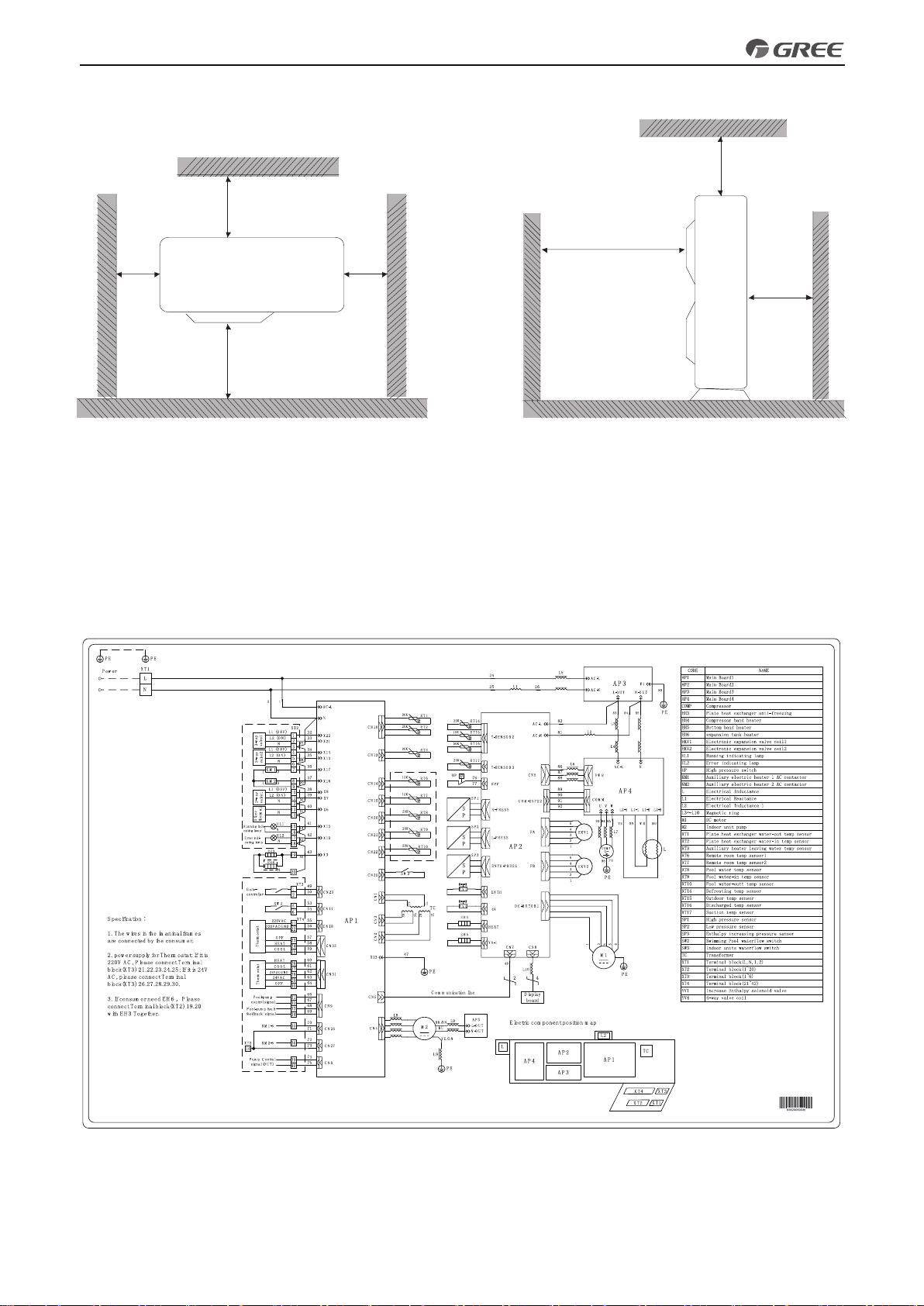
1.1 Installation Positions of the Mini Chiller
(1). Avoid direct sunshine.
(2). Monobloc unit must be installed on a rm and solid support.
(3). Ensure the hanger rod, ceiling and building structure have sufcient strength to support the weight of air
conditioner unit.
(4). Avoid placing the monobloc unit under window or between two constructions, hence to prevent normal
operating noise from entering the room.
(5). Air ow at inlet and outlet shall not be blocked.
(6). Install at a well-ventilated place, so that the machine can absorb and discharge sufcient air.
(7). Do not install at a place where ammable or explosive goods exist or a place subject to severe dust,