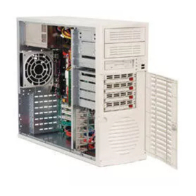
Data General AViiON 530 Series Operator's manual

Customer Documentation
P R O D U C T L I N E


Setting Up, Starting, Expanding, and
Maintaining AViiON530 and 4600
Series Computers
014–002091–01
C pyright Data General C rp rati n, 1991, 1992
All Rights Reserved
Printed in the United States f America
Rev. 01June, 1992
Ordering N . 014-002091

Notice
DATA GE ERAL CORPORATIO (DGC) HAS PREPARED THIS DOCUME T FOR USE BY DGC PERSO EL,
CUSTOMERS, A D PROSPECTIVE CUSTOMERS. THE I FORMATIO CO TAI ED HEREI SHALL OT BE
REPRODUCED I WHOLE OR I PART WITHOUT DGC'S PRIOR WRITTE APPROVAL.
DGC reserves the right to make changes in specifications and other information contained in this document without prior
notice, and the reader should in all cases consult DGC to determine whether any such changes have been made.
THE TERMS A D CO DITIO S GOVER I G THE SALE OF DGC HARDWARE PRODUCTS A D THE LICE SI G
OF DGC SOFTWARE CO SIST SOLELY OF THOSE SET FORTH I THE WRITTE CO TRACTS BETWEE DGC
A D ITS CUSTOMERS. O REPRESE TATIO OR OTHER AFFIRMATIO OF FACT CO TAI ED I THIS
DOCUME T I CLUDI G BUT OT LIMITED TO STATEME TS REGARDI G CAPACITY, RESPO SE-TIME
PERFORMA CE, SUITABILITY FOR USE OR PERFORMA CE OF PRODUCTS DESCRIBED HEREI SHALL BE
DEEMED TO BE A WARRA TY BY DGC FOR A Y PURPOSE, OR GIVE RISE TO A Y LIABILITY OF DGC
WHATSOEVER.
I O EVE T SHALL DGC BE LIABLE FOR A Y I CIDE TAL, I DIRECT, SPECIAL OR CO SEQUE TIAL
DAMAGES WHATSOEVER (I CLUDI G BUT OT LIMITED TO LOST PROFITS) ARISI G OUT OF OR RELATED
TO THIS DOCUME T OR THE I FORMATIO CO TAI ED I IT, EVE IF DGC HAS BEE ADVISED, K EW OR
SHOULD HAVE K OW OF THE POSSIBILITY OF SUCH DAMAGES.
AViiON, CEO, DASHER, DA APREP, DESK OP GENERA ION, ECLIPSE, ECLIPSE MV/4000,
ECLIPSE MV/6000, ECLIPSE MV/8000, GENAP, INFOS, microNOVA, NOVA, PRESEN , PROXI,
SWA , RENDVIEW, and WALKABOU are U.S. registered trademarks of Data General Corporation; and
AOSMAGIC, AOS/VSMAGIC, AROSE/PC, ArrayPlus, AV Object Office, AV Office, BaseLink, BusiGEN,
BusiPEN, Busi EX , CEO Connection, CEO Connection/LAN, CEO Drawing Board, CEO DXA, CEO Light,
CEO MAILI, CEO Object Office, CEO PXA, CEO Wordview, CEOwrite, COBOL/SMAR , COMPUCALC,
CSMAGIC, DASHER/One, DASHER/286, DASHER/286-12c, DASHER/286-12j, DASHER/386,
DASHER/386-16c, DASHER/386-25, DASHER/386-25k, DASHER/386SX, DASHER/386SX-16,
DASHER/386SX-20, DASHER/486-25, DASHER II/486-33 E, DASHER/LN, DA A GENERAL/One,
DESK OP/UX, DG/500, DG/AROSE, DGConnect, DG/DBUS, DG/Fontstyles, DG/GA E, DG/GEO, DG/HEO,
DG/L, DG/LIBRARY, DG/UX, DG/XAP, ECLIPSE MV/1000, ECLIPSE MV/1400, ECLIPSE MV/2000,
ECLIPSE MV/2500, ECLIPSE MV/3500, ECLIPSE MV/5000, ECLIPSE MV/5500, ECLIPSE MV/5600,
ECLIPSE MV/7800, ECLIPSE MV/9300, ECLIPSE MV/9500, ECLIPSE MV/9600, ECLIPSE MV/10000,
ECLIPSE MV/15000, ECLIPSE MV/18000, ECLIPSE MV/20000, ECLIPSE MV/30000, ECLIPSE MV/40000,
ECLIPSE MV/60000, FORMA- EX , GA EKEEPER, GDC/1000, GDC/2400, Intellibook, microECLIPSE,
microMV, MV/UX, PC Liaison, RASS, REV-UP, SLA E, SPARE MAIL, SUPPOR MANAGER, EO,
EO/3D, EO/Electronics, URBO/4, UNI E, and XODIAC are trademarks of Data General Corporation.
UNIX is a U.S. registered trademark of Unix System Laboratories, Inc.
NFS is a U.S. registered trademark and ONC is a trademark of Sun Microsystems, Inc.
The etwork Information Service ( IS) was formerly known as Sun Yellow Pages. The functionality of the two remains
the same; only the name has changed. The name Yellow Pages is a registered trademark in the United Kingdom of
British Telecommunications plc and may not be used without permission.
IBM PC A is a U.S. registered trademark of International Business Machines Corporation.
eflon is a U.S. registered trademark of E.I. DuPont de emours and Company.
Setting Up, Starting, Expanding, and Maintaining AViiO 530 and 4600 Series Computers
014-002091-01
Revision History:
Original Release - September, 1991
First Revision - June, 1992
A vertical bar in the margin of a page indicates substantive technical change
from the previous revision.

NOTE
This equip ent has been tested and found to co ply with the li its for a Class A digital device, pursuant to Part 15 of
the FCC Rules. These li its are designed to provide reasonable protection against har ful interference when the
equip ent is operated in a co ercial environ ent. This equip ent generates, uses, and can radiate radio frequency
energy and, if not installed and used in accordance with the instruction anual, ay cause har ful interference in which
case the user will be required to correct the interference at his own expense. Testing was done with shielded cables.
Therefore, in order to co ply with the FCC regulations, you ust use shielded cables with your installation.
WARNING
Changes or odifications to this unit not expressly approved by the party responsible for co pliance could void the user's
authority to operate the equip ent.
This device co plies with Part 15 of the FCC rules. Operation is subject to the following two conditions:
(1) this device ay not cause har ful interference, and (2) this device ust accept any interference received, including
interference that ay cause undesired operation.
This digital apparatus does not exceed the Class A li its for radio noise e issions fro digital apparatus set out in the
Radio Interference Regulations of the Canadian Depart ent of Co unications.
Le présent appareil nu érique n' é et pas de bruits radioélectriques dépassant les li ites applicables aux appareils
nu ériques de la classe A prescrites dans le Règle ent sur le brouillage radioélectrique édicté par le inistère des
Co unications du Canada.


v
014–002091
Preface
We wrote this manual for anyone who sets up and maintains A iiON530 and
4600 series computer system hardware. Although it addresses readers with some
computer hardware experience, you do not need knowledge of A iiON or RISC-based
computer technology to use this manual.
The first three chapters of this manual describe how to unpack, set up, and start a
basic new computer system. They cover a hardware installation sequence that ends
with you ready to install your system software. Subsequent chapters explain how to
set up and connect external mass-storage units, and how to customize operating
parameters for devices connected directly to the system board. The final six chapters
in this manual provide detailed information and illustrated instructions for replacing
failing parts and for adding mass-storage devices, expansion memory, and option
boards to an installed system. Appendixes provide technical specifications for computer
system hardware, instructions for using the System Control Monitor (SCM), and
suggestions for solving powerup problems.
NOTE: This manual does not describe how to set up or install MEbus option
boards, or the devices that connect to them. If your system includes
MEbus options, refer to Setting Up and Installing VMEbus Options in
AViiONSystems (DGC part number 014-001867) for instructions.
How We Organized This Manual
We organized the information in this manual as follows:
Provides information you need before starting any work. Begins with an overview of
base computer system components and options. Also includes site preparation and
unpacking instructions, an inventory worksheet for cables and cords, and a checklist to
complete before you set up your workstation.
Describes how to connect the system console and computer unit power cord. For the
A iiON 530 series, describes how to install the monitor, keyboard, and mouse. For
systems without external mass-storage devices, explains how to terminate an internal
SCSI bus. Also describes cabling for the following optional devices:
•asynchronous devices such as a modem, serial printer, or plotter.
•local area network (LAN) transceiver.
•parallel printer.

Preface
vi 014–002091
Chapter 3 Startin and Stoppin Your Computer System
Explains how to correctly power the computer system up and down and describes
routine irmware powerup testing.
NOTE: Chapter 3 describes a irst powerup sequence to the point at which you
should install your operating system so tware. It then provides
re erences to the appropriate documentation or your next step.
Chapter 4 Settin Up and Installin a SCSI Bus
Describes how to con igure a Small Computer System Inter ace (SCSI) bus. Includes
de ault and recommended SCSI identi ication numbers, operating parameters or
individual drives, terminating rules, and cabling restrictions. Also provides
worksheets or planning a SCSI con iguration, and instructions or connecting external
SCSI devices and subsystems to the computer unit.
Chapter 5 Usin the SCM Confi uration Menus
Describes menus you can use to view or change con iguration parameters or devices
connected to the system board. Also describes changing the system automatic boot
path rom the de ault DG/UXinstallation path.
Chapter 6 Expandin and Maintainin Your Computer System
Provides general procedures you should ollow each time you add or replace an internal
system component, and describes how to respond to hardware problems. Explains how
to review system con iguration parameters, and provides instructions and worksheets
or calculating the power requirements o proposed con igurations.
Further describes how to avoid electrostatic discharge (ESD) damage while working
inside the computer unit chassis, and explains how to open and close the chassis
covers.
Chapters 7 throu h 12 Addin and/or Replacin ...
Each o these six chapters describes how to expand your system by adding a new
internal component, or maintain the system by replacing a ailed Customer
Replaceable Unit (CRU). Each re ers to Chapter 6 or prerequisite in ormation that
applies to all CRUs.
Appendix A Technical Specifications
Lists detailed physical, environmental, and electrical speci ications or base hardware
and optional components.
Appendix B Usin the System Control Monitor
Explains how to reach the system irmware and use basic SCM commands to boot,
program, and debug your system.
Appendix C Solvin Powerup Problems and
Exitin the DG/UXInstaller
Provides suggestions or resolving powerup problems such as blank screen display or
unreadable text messages. Also describes exiting routine irst powerup to test your
system hardware be ore installing the DG/UX operating system.

Preface
vii
014–002091
Reading Paths
The following reading paths explain which chapters and sections you should read and
in what order, depending on the task you need to do.
Reading Path for Setting Up a New Computer System
Review site requirements, and then unpack and inventory your system, as described in
Chapter 1. Then read Chapter 2, following those instructions that apply to your
configuration. Read Chapter 3, Starting and Stopping Your Computer System" before
you power up your new computer system.
•If your system includes external SCSI devices or subsystems, set them up as
described in Chapter 4 before continuing with the instructions in Chapter 3 to start
your system.
•If your system includes MEbus options (such as a terminal controller or
asynchronous device controller), set up and connect the appropriate devices as
described in the device-specific documentation and Setting Up and Installing
VMEbus Options in AViiONSystems. Then continue with the instructions in
Chapter 3 to start your system.
•If your system includes devices connected to the system board whose operating
parameters conflict with the defaults listed in Chapter 2 and which are required for
the first powerup, read the appropriate instructions in Chapter 5 before continuing
with the instructions in Chapter 3 to start your system.
Reading Path for Powerup Procedures or Problems
Refer to Chapter 3, Starting and Stopping Your Computer System," for a description
of the sequence your computer system undergoes when powering up normally. Refer
to Appendix C, Solving Powerup Problems and Exiting the DG/UXInstaller," for
troubleshooting suggestions. For steps to properly shut down the computer system,
refer to the last section of Chapter 3, Shutting Down the Computer System."
Reading Path for Expanding the Computer System
NOTE: To add MEbus options to your system, first verify your proposed system
configuration as described in Chapter 6; then refer to Setting Up and
Installing VMEbus Options in AViiONSystems.
Internal CRUs
An internal CRU (Customer Replaceable Unit) is any component you can install inside
the computer unit chassis. To add an internal part, follow the instructions in Chapter
6 to verify your proposed configuration and open your system; then proceed to the
appropriate chapter in this manual.

Preface
viii 014–002091
Adding Mass–Storage Devices
To add a drive to a mass-storage housing unit, veri y your proposed SCSI
con iguration as described in Chapter 4; then re er to the manual that came with the
drive and to the manual that came with the housing unit or instructions.
To connect a stand-alone mass-storage drive or housing unit, re er to Chapter 4 and
the manual that came with the unit.
To add an internal device, re er irst to Chapter 4 to veri y your proposed bus
con iguration, and then re er to Chapter 6 to veri y your proposed system
con iguration. Follow the instructions in Chapter 6 be ore adding the drive as
described in Chapter 7.
Adding an External Option
To add an external option (such as a LAN transceiver, modem, or other externally
connected peripheral), ollow the steps in the appropriate section o Chapter 2 to
con igure the device and connect the cabling. Re er to the manual that came with the
option or additional in ormation and instructions.
Reading Path for Replacing Parts
NOTE: To replace VMEbus options in or connected to your system, re er to
Setting Up and Installing VMEbus Options in AViiONSystems.
Internal CRUs
An internal CRU (Customer Replaceable Unit) is any component you can replace that
is housed inside the computer unit chassis. To replace an internal part, ollow the
instructions in Chapter 6 to open your system; then proceed to the appropriate chapter
in this manual.
Replacing Mass–Storage Devices
To replace a drive in a mass-storage housing unit, re er to the manual that came with
the drive and to the manual that came with the housing unit or instructions. Re er to
Chapter 4 or operating parameters.
To replace a stand-alone mass-storage drive or housing unit, re er to Chapter 4 and
the manual that came with the unit.
To replace an internal device, ollow the instructions in Chapter 6 to open your system
be ore removing and re-installing the drive as described in Chapter 7.
Replacing an External Option
To replace an external option (such as a LAN transceiver, modem, or other externally
connected peripheral), ollow the steps in the appropriate section o Chapter 2 to
con igure the replacement device, disconnect the old part, and then reconnect the new
part. Re er to the manual that came with the option or additional in ormation and
instructions.

Preface
ix
014–002091
Related Documents
You received a comprehensive documentation package with your A iiON 530 or
4600 series computer system. Those documents specifically mentioned within the text
of this manual appear below. Refer to the document Guide to AViiONand DG/UX
System Documentation (069-701085) for a complete list of related documentation.
Customizin the DG/UXSystem (093-701101)
Describes how to perform tasks that customize the DG/UX system to your site's
needs. Included are descriptions of how to add user home directories, printers,
terminals, third-party packages, operating system clients and secondary
releases.
Ethernet/IEEE 802.3 Local Area Network Installation Guide (014-000793)
Explains how to install both the coaxial cable plant of an Ethernet local area
network (LAN) and the transceivers that connect the network to a
communications controller.
Installin and Maintainin the CSS2/DC (014-002061)
Describes how to unpack, inspect, install, and power up the unit. Explains how
to replace the power supply, line cord, fan; and provides general instructions for
replacing a drive. Lists physical, electrical, and environmental specifications of
the subsystem.
Installin and Operatin the Model 10565 Peripheral Housin Unit (014-001810)
Describes how to unpack, inspect, install, and power up the unit. Explains how
to replace the power supply, line cord, and fan; and provides general instructions
for replacing a drive. Lists physical, electrical, and environmental specifications
of the peripheral housing unit.
Installin the DG/UXSystem (093-701087)
Describes how to install the DG/UX operating system on A iiON 530 and
4600 series hardware.
Settin Up and Installin VMEbus Options in AViiONSystems (014-001867)
Describes how to jumper MEbus controllers to operate in an A iiON
environment. Explains how to install and remove the controller boards in the
system's MEbus card cage, and supplies instructions for connecting external
devices to the controller boards.
Usin AViiONSystem Dia nostics (014-001863)
Describes how to use menu-based utilities to verify system hardware; test the
graphics monitor, keyboard, and mouse;check for faults in LAN connections; and
maintain cartridge tape and diskette media.

Preface
x014–002091
Reader, Please Note
This manual uses the following terms and conventions:
Within text, press New Line" means that you should press the New Line key on the
Data General DASHERkeyboard. If you are using a keyboard compatible with the
industry-standard IBM PC ATkeyboard, the equivalent key is usually marked
Enter, Return, or with a symbol such as .
The term workstation refers to any single-user AViiON model that provides graphics
computing either as a stand-alone station or as a network client to a server system.
The term server refers to the computer system that provides user services through
direct terminal lines and/or a local area network (LAN). An AViiON server could be a
stand-alone server, which provides operating system support via direct terminal
access, or a network server, which provides operating system support to client
computers across a local area network. Some computers function as both stand-alone
and network servers. The term client refers to any computer that receives operating
system or file services from a server system across a LAN.
The system console refers to the keyboard and display device that receives powerup
diagnostic test messages and from which you bring up your operating system. The
system console communicates directly with the AViiON 530 or 4600 series computer's
system board. A workstation's system console consists of the graphics monitor and
graphics keyboard. A server's system console consists of an asynchronous terminal
and keyboard.
Within text, we use the following symbols:
Symbol Means
Press the New Line, Carriage Return (CR), Return, or Enter key
on your system console keyboard.
SCM> The default System Control Monitor (SCM) prompt.
The default DG/ X superuser shell prompt.
In examples we use
This typeface to show system queries and responses.

Preface
xi
014–002091
Contacting Data General
Data General wants to assist you in any way it can to help you use its products. Please
feel free to contact the company as outlined below.
Manuals
If you require additional manuals, please use the enclosed IPS order form
(United States only) or contact your local Data General sales representative.
Telephone Assistance
If you are unable to solve a problem using any manual you received with your system,
free telephone assistance is available with your hardware warranty and with most
Data General software service options. If you are within the United States or Canada,
contact the Data General Customer Support Center (CSC) by calling
1-800-DG-HELPS. Lines are open from 8:00 a.m. to 5:00 p.m., your time, Monday
through Friday. he center will put you in touch with a member of Data General's
telephone assistance staff who can answer your questions.
For telephone assistance outside the United States or Canada, ask your Data General
sales representative for the appropriate telephone number.
Joining Our Users Group
Please consider joining the largest independent organization of Data General users,
the North American Data General Users Group (NADGUG). In addition to making
valuable contacts, members receive FOCUS monthly magazine, a conference discount,
access to the Software Library and Electronic Bulletin Board, an annual Member
Directory, Regional and Special Interest Groups, and much more. For more
information about membership in the North American Data General Users Group, call
1-800-253-3902 or 1-508-443-3330.
End of Preface

Preface
xii 014–002091

xiii
014–002091
Contents
Chapter 1 – Getting Started
AViiON 530 and 4600 Series Computers 1Ć1....................................
Basic System and Options 1Ć2...........................................
About the System Console (AViiON 4600 Series) 1Ć5.......................
About the Graphics Monitor (AViiON 530 Series) 1Ć6......................
About the Keyboard and Mouse (AViiON 530 Series) 1Ć6...................
About VMEbus Options 1Ć7.............................................
About Mass-Storage Drives 1Ć7.........................................
Before You Start 1Ć8.........................................................
Selecting a Site 1Ć8.....................................................
npacking and Inspecting Your Equipment 1Ć9...........................
Gathering Documentation and Media 1Ć15.................................
Chapter 2 – Setting Up Your Computer System
Connecting the System Console (AViiON 4600 Series) 2Ć1.......................
Connecting the Graphics Monitor (AViiON 530 Series) 2Ć3......................
Connecting the Keyboard (AViiON 530 Series) 2Ć5..............................
Connecting the Mouse (AViiON 530 Series) 2Ć6.................................
Connecting a Local Area Network Cable 2Ć8...................................
Connecting Asynchronous Devices 2Ć10.........................................
Connecting Synchronous Devices 2Ć12..........................................
Connecting a Parallel Printer 2Ć13.............................................
Terminating an Internal SCSI Bus 2Ć14........................................
Connecting the Computer nit Power Cord 2Ć16................................
Chapter 3 – Starting and Stopping Your Computer System
Starting the Computer System 3Ć1............................................
Powering p 3Ć1.......................................................
Your Next Step 3Ć5.....................................................
Shutting Down Your Computer System 3Ć8....................................
Powering Down 3Ć8.....................................................
Resetting the Computer System 3Ć9......................................
Restarting Your System 3Ć10.............................................
Chapter 4 – Setting Up and Installing a SCSI Bus
Planning a SCSI Bus Configuration 4Ć1........................................
Identifying SCSI Drives 4Ć3.............................................
SCSI Bus Cabling Rules 4Ć6.............................................
Configuring Device Operating Parameters 4Ć7.............................
Terminating the External SCSI Bus 4Ć7..................................

Contents
xiv 014–002091
Installing a SCSI Bus and SCSI Devices 4Ć10....................................
Installing Configuration Jumpers 4Ć11....................................
Connecting the SCSI Bus to SCSI devices 4Ć12.............................
erminating the SCSI Bus 4Ć12...........................................
Connecting an External SCSI Bus to the Computer Unit Rear Panel 4Ć13..........
Chapter 5 – Using the SCM Configuration Menus
Summary of Menus and Menu Conventions 5Ć1................................
Changing the Default System Boot Path 5Ć3....................................
Specifying Boot Devices 5Ć3.............................................
Booting from Disk or ape 5Ć4...........................................
Booting Over a Local Area Network 5Ć5..................................
Examples of Valid Boot Paths 5Ć6........................................
Changing Console Parameters 5Ć8.............................................
Changing the System Console Baud Rate 5Ć9..............................
Changing the System Console Character Length 5Ć10.......................
Changing the System Console Mode 5Ć11..................................
Enabling or Disabling Flow Control 5Ć12..................................
Changing the Keyboard Language 5Ć12....................................
Changing the Screen-Saver imeout 5Ć14.................................
Changing Modem Port Parameters 5Ć15........................................
Changing the Modem Port Baud Rate 5Ć16.................................
Changing the Modem Port Character Size 5Ć17.............................
Changing the Mouse Baud Rate 5Ć17...........................................
Viewing the System Configuration 5Ć18.........................................
Changing the VME A24 Configuration 5Ć19.....................................
Chapter 6 – Expanding and Maintaining
Your Computer System
Maintaining Your System 6Ć1.................................................
If a Computer System Problem Occurs 6Ć2................................
Reviewing System Specifications 6Ć2..........................................
Verifying Support for Your Configuration 6Ć2..............................
Calculating Power Requirements 6Ć3.....................................
Avoiding Electrostatic Discharge (ESD) Damage 6Ć7............................
Emergency Procedures (without an ESD kit) 6Ć7..........................
Installing Board Jumpers and Setting Switches 6Ć8.............................
Installing Jumpers 6Ć8..................................................
Setting Switches 6Ć9....................................................
Opening the Computer Unit 6Ć10..............................................
Removing the Side Covers 6Ć10...........................................
Removing the op Cover 6Ć12............................................
Closing the Computer Unit 6Ć13...............................................
Installing the op Cover 6Ć13.............................................
Installing the Side Covers 6Ć14...........................................

Contents
xv
014–002091
Chapter 7 – Adding or Replacing
Internal Mass–Storage Devices
Supported Mass-Storage Devices 7Ć1.........................................
Mass-Storage Device Locations 7Ć2......................................
Removing a Drive Assembly 7Ć3..............................................
Removing Brackets from a Drive 7Ć6.....................................
Configuring New or Replacement Drives 7Ć7...................................
Installing a Drive Assembly 7Ć9...............................................
Attaching Brackets to a Drive 7Ć9........................................
Completing the Drive Assembly Installation 7Ć10...........................
Adding or Replacing the SCSI Adapter Board 7Ć14...............................
Removing the SCSI Adapter Board 7Ć14...................................
Installing the SCSI Adapter Board 7Ć16....................................
Replacing the erminator Plug 7Ć17............................................
Chapter 8 – Adding or Replacing Memory Modules
Rules for Installing Memory Modules 8Ć2......................................
Removing Memory Modules 8Ć4...............................................
Installing Memory Modules 8Ć6...............................................
Chapter 9 – Adding or Replacing a CPU Complex and
System Board Options
Adding or Replacing a CPU Complex Board 9Ć2................................
Removing a CPU Complex Board 9Ć2.....................................
Specifying CPU Configurations 9Ć4......................................
Installing a CPU Complex Board 9Ć6.....................................
Adding or Replacing an I/O Expansion Board 9Ć7...............................
Removing an I/O Expansion Board 9Ć8...................................
Installing an I/O Expansion Board 9Ć11....................................
Adding or Replacing a Graphics or Z-Buffer Board (530 series) 9Ć15..............
Removing the Graphics or Z-Buffer Board 9Ć16............................
Installing the Graphics or Z-Buffer Board 9Ć18............................
Chapter 10 – Replacing the System Board
Removing the System Board 10Ć1..............................................
Installing the System Board 10Ć5..............................................
Chapter 11 – Replacing the Fan Assembly
Removing the Fan Assembly 11Ć1..............................................
Installing the Fan Assembly 11Ć3...............................................
Chapter 12 – Replacing the Power Supply and Fuses
Removing the Power Supply 12Ć1..............................................
Installing the Power Supply 12Ć4...............................................
Replacing the ape/Disk Fuse 12Ć7.............................................

Contents
xvi 014–002091
Appendix A – Technical Specifications
Physical and Environmental Speci ications AĆ1.................................
System Board and System Bus Options AĆ2....................................
VMEbus Backplane and Options AĆ3..........................................
Mass Storage Options AĆ5....................................................
Power Subsystem Speci ications AĆ6...........................................
Workstation Peripherals Speci ications (AViiON 530 Series) AĆ8..................
Integrated I/O Connectors and Signals AĆ11.....................................
Appendix B– Using the System Control Monitor
Getting to the SCM BĆ1......................................................
Using SCM Commands BĆ3...................................................
Appendix C – Solving Powerup Problems
and Exiting the DG/UX Installer
Solving Powerup Problems CĆ2................................................
Exiting the Installer System CĆ10..............................................

Contents
xvii
014–002091
Tables
Table
1-1 Voltage Suffixes 1Ć12...................................................
1-2 Cable/Cord Inventory Worksheet 1Ć14....................................
1-3 Language Suffixes for Keyboard Part Numbers 1Ć15.......................
4-1 Default SCSI Device ID Numbers 4Ć3...................................
5-1 Boot Specifications for Disk and Tape Drives 5Ć5.........................
5-2 Specifications for LAN Devices 5Ć6......................................
5-3 Alternate Keyboard Codes 5Ć14..........................................
7-1 AViiON 530 and 4600 Series Internal Mass-Storage Drives 7Ć2............
7-2 SCSI Device Identification Numbers 7Ć8.................................
8-1 Valid Memory Configurations 8Ć4.......................................
A-1 Internal Component Current Requirements for AViiON 530 and 4600 AĆ7..
B-1 SCM Line Editing Features and Keyboard Control Sequences BĆ4..........
B-2 Summary of SCM Commands and Command Functions BĆ5...............
B-3 Mnemonics and Parameters for Bootable Devices BĆ8.....................
B-4 Controller (cntrl) Parameter Values BĆ9.................................
B-5 Default SCSI Device ID and LUN Numbers BĆ10..........................
C-1 Reading Path For Powerup Testing Hangs CĆ1...........................
C-2 uick Reference for Powerup Problems (Graphics Console) CĆ3............
C-3 uick Reference for Powerup Problems (Nongraphics Console) CĆ4.........

Contents
xviii 014–002091
Figures
Figure
1Ć1 AViiON 530 Series Computer 1Ć1.......................................
1Ć2 AViiON 530 and 4600 Series Rear Panel and Connectors 1Ć5...............
1Ć3 Color Graphics Monitor and Controls 1Ć6................................
1Ć4 Removing the Shipping Cover 1Ć9.......................................
1Ć5 Positioning the Computer Unit Upright 1Ć10..............................
1Ć6 Removing the Shipping Tray and Packing Material 1Ć10...................
1Ć7 Removing the Computer from the Packing Tray 1Ć11......................
1Ć8 Voltage Setting Label 1Ć13..............................................
1Ć9 Installation Checklist 1Ć16..............................................
2Ć1 Connecting the System Console 2Ć2.....................................
2Ć2 Graphic Monitor Power Switch 2Ć4......................................
2Ć3 Plugging the Cables and Power Cord into the
Monitor and Computer Unit 2Ć4........................................
2Ć4 Connecting the Color Monitor Power Cord 2Ć5...........................
2Ć5 Connecting the Graphics Keyboard 2Ć6..................................
2Ć6 Connecting the Mouse 2Ć7.............................................
2Ć7 Connecting the LAN Transceiver Cable to the Computer Unit 2Ć9..........
2Ć8 Attaching and Securing the LAN Transceiver Cable 2Ć9...................
2Ć9 Connecting Devices to the Computer Unit Serial Ports 2Ć11................
2Ć10 Connecting a Synchronous Device to the Computer Unit 2Ć12..............
2Ć11 Connecting a Parallel Printer to the Computer Unit 2Ć13...................
2Ć12 AViiON 530 and 4600 Series SCSI Bus Connectors 2Ć14....................
2Ć13 Installing the SCSI Bus Terminator Plug 2Ć15............................
2Ć14 Securing a SCSI Bus Terminator 2Ć15....................................
2Ć15 Connecting the Computer Unit Power Cord 2Ć17..........................
3Ć1 Monitor Power Switch 3Ć2.............................................
3Ć2 Peripheral Subsystem Power Switches 3Ć2...............................
3Ć3 Computer Unit Power Switch and LED Power-On Indicator 3Ć3...........
3Ć4 Computer Unit Reset and Abort Switch 3Ć9..............................
4Ć1 AViiON 530 and 4600 Series SCSI Bus Connectors 4Ć2....................
4Ć2 Sample SCSI Device Identification Configuration 4Ć5.....................
4Ć3 Daisy Chain and SCSI Bus Cable Lengths 4Ć6............................
4Ć4 SCSI Bus Configuration orksheet 4Ć8..................................
4Ć5 Sample Configuration orksheet 4Ć9....................................
4Ć6 SCSI Cable Rules and Sample Device IDs 4Ć10............................
4Ć7 AViiON 530 and 4600 Series External SCSI Connectors 4Ć13...............
4Ć8 Removing the SCSI Bus Terminator Plug 4Ć14............................
4Ć9 Plugging Together SCSI Bus Connectors 4Ć14.............................
4Ć10 Securing a SCSI Cable Connection 4Ć14..................................
This manual suits for next models
1
Table of contents
Other Data General Desktop manuals

