Data Industrial 200 Series User manual

200 Series
Plastic Tee Type Flow Sensors
by Data Industrial
Owner's Manual
Introduction
Used in conjunction with any Data Industrial flow monitor or
transmitter, Data Industrial non-magnetic flow sensors provide an
accurate reading of the rate of liquid flow as well as total
accumulated flow. A number of sensor models are offered,
which cover applications for a wide range of pipe si es and
pressure/temperature specifications.
The flow sensors generate a frequency which is proportional to flow rate. An internal preamplifier allows the
pulse signal to travel up to 2000 feet without further amplification. Power to operate the sensor is provided by
the flow monitor. The impeller bearing assembly, shaft and O-rings are replaceable in the field.
Data Industrial flow sensors feature a closed, six-bladed impeller design, using a proprietary, non-magnetic
sensing technology. The forward-swept impeller shape provides higher, more constant torque than four-bladed
impeller designs, and is less prone to fouling by water-borne debris. The forward-curved shape, coupled with
the absence of magnetic drag, provides improved operation and repeatability, even at lower flow rates. As the
liquid flow turns the impeller, a low impedance signal is transmitted with a frequency proportional to the flow rate.
Sensors of similar type are interchangeable, so there is no need for recalibration after servicing or
replacement.
Electronic Types
Data Industrial provides several basic sensor configurations using the same impeller element. This allows for a
wide range of applications and pipe si es. Sensors are normally supplied with 20 feet of 2-conductor 20 AWG
shielded U.L. type PTLC 105°C cable. Optional sensors designated with the prefix "IR" feature two single
conductor 18 AWG solid copper wire leads 48 inches in length with U.L. Style 116666 direct burial insulation.
These IR models are used in below grade applications such as irrigation, municipal, and groundwater monitor-
ing. All 200 series sensor electrical components are self-contained. Pressure/temperature ratings for the
various models are contained in the Specifications section of this manual. These models can be further de-
scribed as follows:
"Standard" Sensor
Designed for indoor or protected area applications such as HVAC, pump control, and industrial process monitor-
ing where the flow rates are between 0.5-30 feet/second and temperatures are below 221°F. Standard sensors
are supplied with 20 feet of 2-conductor 20 AWG shielded U.L. type PTLC 105°C cable.
"IR" Sensor
Designed for below grade applications such as irrigation, municipal, and groundwater monitoring where the flow
rates are between 0.5-30 feet/second and temperatures are below 180°F. IR sensors are supplied with two
single conductor, 18 AWG solid copper wire leads 48 inches in length with U.L. Style 116666 direct burial
insulation.
PN# 72022
10/10/02 Rev E1

Data Industrial Plastic Tee Type Flow Sensor Manual
2
"FM/CSA" Sensor
Designed for indoor or protected area applications where intrinsic safety is required and the flow rates are
between 0.5-30 feet/second and temperatures are below 221°F. FM/CSA sensors are supplied with 20 feet of
2-conductor 20 AWG shielded U.L. type PTLC 105°C cable. These sensors must be used with an approved
safety barrier.
"Magnetic" Sensor
Designed for use with the Series 1400 battery powered flow monitor in above or below or grade applications
such as irrigation, municipal, and groundwater monitoring where the flow rates are between 1-30 feet/second
and temperatures are below 221°F.
Model 22 PV (Formerly 220P)
These models feature a modified
PVC tee with solvent weld socket
end connections, and a removable,
PPS or PVDF sensor insert. Si es of
1 1/2, 2, 3 and 4 are available.
Model 22 PD and 220PF
No longer in production - see
obsolete manuals @
www.dataindustrial.com
Mechanical Installation
General
The accuracy of flow measurement
for all flow measuring devices is
highly dependent on proper location
of the sensor in the piping system.
Irregular flow velocity profiles caused
by valves, fittings, pipe bends, etc.
can lead to inaccurate overall flow
rate indications even though local
flow velocity measurement may be
accurate. A sensor located in the
pipe where it can be affected by air
bubbles, floating debris, or sediment
may not achieve full accuracy and
could be damaged. Data Industrial
flow sensors are designed to operate
reliably under adverse conditions,
but the following recommendations
should be followed to ensure
maximum system accuracy:
1) Choose a location along the pipe where 10 pipe diameters upstream and 5 pipe diameters downstream of
the sensor provide no flow disturbance. Pipe bends, valves, other fittings, pipe enlargements and reductions
should not be present in this length of pipe.
2) The preferred location for the sensor around the circumference of a hori ontal pipe is on top. If trapped air or
debris will interfere, then the sensor should be located further around the pipe from the top but not more than
45 degrees from top dead center. The sensor should never be located at the bottom of the pipe, as sediment
may collect there. Locations off top dead center cause the impeller friction to increase, which may affect
performance at low flow rates and increase wear. Any circumferential location is correct for installation in
vertical pipes. Rising flow preferred to reduce effects of any trapped air.
200 Series Plastic Tee Sensors Matrix (1½" to 4")
Example:
2
x
x
x
x
x
-
x
x
x
x
Style
Tee Mounted
28
Material
PVC
PV
CPVC
CPV
Size
1.5"
15
2"
20
3"
30
4"
40
Electronics Housing
PPS
0
PVDF
1
ELECTRONICS
Magnetic
2
FM/CSA Approved
4
Standard
5
IR-Irrigation (not available with PVDF sensors)
6
O-RING
Viton
®
0
EPDM
1
Kalrez
®
2
Food Grade Silicone
3
Neoprene
4
Chemraz
®
5
Teflon
®
Encapsulated Viton
®
6
Teflon
®
Encapsulated Silicone
7
Buna N
8
SHAFT
Zirconia Ceramic
0
Hastalloy C
®
1
Tungsten Carbide
2
Titanium
3
Monel
®
5
316 Stainless Steel
6
Tantalum
7
IMPELLER
Nylon
1
Tefzel
®
2
BEARING
Pennlon
1
Tefzel®2
Teflon
®3
Chemraz
®
is a registered trademark of Green Tweed.
Kalrez
®
, Viton
®
, Teflon
®
, Tefzel
®
are registered trademarks of Dupont Dow Elastomers.
Monel is a registered trademark of Inco Alloys Int’l.
Hastalloy C is a registered trademark of Haynes Int’l Inc.

Data Industrial Plastic Tee Type Flow Sensor Manual
3
Mechanical Installation for 22 PV Plastic Tee Sensors
1) Note intended direction of flow as indicated by arrows on the tee. There must be free, unrestricted pipe for
at least 10 diameters upstream and 5 diameters downstream of the tee.
2) Remove the clevis pin and remove the sensor from the tee.
3) Properly clean the pipe ends and tee sockets.
4) For 228PV, solvent cement the pipe to the tee.
5) Reinstall sensor in tee as follows:
a) Align the flow arrow on the top of the sensor housing in the direction of flow.
b) Carefully press sensor straight into tee.
c) Install clevis pin through tee, sensor, and conduit cap, and install cotter ring.
Electrical Installation "Standard" sensors
1) Route the cable from the sensor to a Data Industrial flow monitor/transmitter. The cable may be extended
up to 2000 feet, using 2-conductor shielded 20 AWG or larger stranded copper wire. Be sure to leave
enough flexibility in the cable or conduit to allow for future service of sensor, if necessary.
2) When connecting to a Data Industrial flow monitor/transmitter, locate the section of terminal strip on the
monitor labeled "SENSOR INPUT" or "SENSOR". Connect the red wire to "IN", "SIGNAL(+)" OR
"SIGNAL" terminal and the black wire to "GND", "SIGNAL(-)", or "COM" terminal and the shield drain wire
(if applicable) to "SLD".
3) When interfacing with other equipment consult manufacture for input designations. The signal wave forms
and power requirements are as shown in the Specifications section. Refer to Technical Bulletin 81 @
www.dataindustrial.com
Electrical Installation "IR" sensors
The sensor leads are supplied with watertight caps over the ends.
1) DO NOT remove the plastic caps from the sensor leads until ready to splice. See Application Note 47 and
Technical Bulletin 52 @ www.dataindustrial.com
2) Use a twisted pair cable suitable for direct burial to connect the sensor to the transmitter, monitor, or
controller. Multi-pair telecommunication cable or direct burial cables may be used.
3) Make a water tight splice. Two part epoxy type waterproof kits are recommended. Be sure the epoxy seals
the ends of the cable jacket.
4) Make sure the epoxy is hardened before inverting the splice or dropping it in standing water.
5) DO NOT make an underground splice unless absolutely necessary.
6) Route the cable from the sensor to a Data Industrial flow monitor/transmitter. The cable may be extended
up to 2000 feet, using 2-conductor shielded 20 AWG or larger stranded copper wire with appropriate ratings.
Be sure to leave enough flexibility in the cable or conduit to allow for future service of sensor, if necessary.
7) When connecting to a Data Industrial flow monitor/transmitter, locate the section of terminal strip on the
monitor labeled "SENSOR INPUT" or "SENSOR". Connect the red wire to "IN", "SIGNAL(+)" OR
"SIGNAL" terminal and the black wire to "GND", "SIGNAL(-)", or "COM" terminal and the shield drain wire
(if applicable) to "SLD".
8) When interfacing with other equipment, the signal wave forms and power requirements are as shown in the
Specifications section. Refer to Technical Bulletin 81 @ www.dataindustrial.com

Data Industrial Plastic Tee Type Flow Sensor Manual
4
Electrical Installation "Magnetic" sensors
The magnetic sensor has a custom wire connector that connects to the series 1400 monitor only. The cable
may be extended up to 100 feet from the sensor. If extension cables are needed they may be ordered from
Data Industrial.
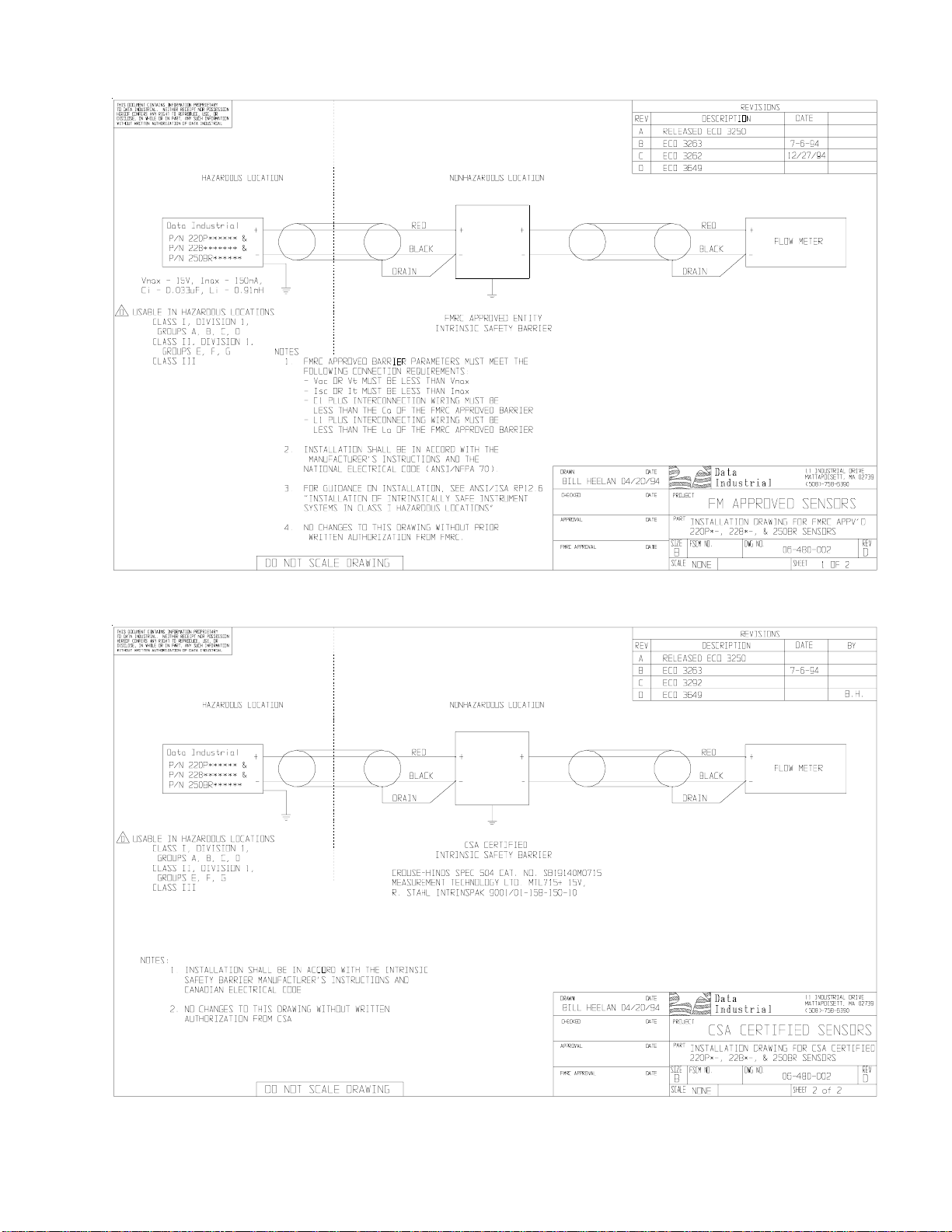
Electrical Installation (FM Sensors)
The Series 200 Sensor is approved, as an entity, as Intrinsically Safe when installed in conformance with Data
Industrial installation drawings 06-480-001 or 06-480-002 (samples shown on Page 5) as specified on the blue
label identifying an intrinsically safe sensor.
Entity approval implies that only the sensor is approved as intrinsically safe. Unless power supplies, equipment,
and instruments connected to the sensor are each rated either explosion-proof or intrinsically safe, these
devices cannot be installed in a ha ardous area. The referenced installation drawing shows such apparatus
located in a non-ha ardous location. Proper interfacing between the ha ardous and non-ha ardous areas must
be provided. It is of absolute importance that this interface be constructed and that all wiring be performed by
qualified contractors. To ensure the Intrinsic Safety of the installation, the connection of the intrinsically safe
sensor to instruments and or power supplies must take place using an approved intrinsically safe barrier located
in a non-ha ardous area. These barriers, listed below, are readily available from various suppliers.
Manufacturer: Barrier:
Crouse-Hinds Spec 504 Cat No. SB19140M0715
Measurement Technology Ltd. MTL 715+ 15 V
R Stahl Intrinspak 9001/01-158-150-10
Cable Length
Part #
5’ 7101
10’ 7108
20’ 7102
50’ 7109
Data Industrial Plastic Tee Type Flow Sensor Manual
5

Data Industrial Plastic Tee Type Flow Sensor Manual
6
Calibration Table for Series 228PV
Calibration
Data Industrial sensors use unique K and offset numbers for calibration. These numbers are derived from
calibration runs using NIST traceable instruments. Using both a K and an offset number provides higher accu-
racy than using a K factor alone. K and offset numbers for each tee configuration are listed in the following table.
Calibration Tables
The table below provides calibration and operation data for Data Industrial Plastic Tee Sensors 1.5 to 4.
Column 1 Sensor Model Number
Column 2 Apparent I.D. - For use with the Series 900 and the Series 1000
Columns 3 and 4 The K value and Offset values to use in our frequency equation:
This equation describes the frequency of the output signal of all Data Industrial flow
sensors. By substituting the appropriate K and Offset values from the table, the
sensors output frequency can be calculated for each pipe si e. This information is
required when calibrating an output board or when using the raw sensor data as
direct output to interface with a device that is not a Data Industrial product.
Column 5 This column indicates the suggested flow range of each tee sensor. Data Industrial
sensors will operate both above and below the indicated flow rates. However, good
design practice dictates the use of this range for best performance.
Sensors should be si ed for flow rather than pipe si e. To prevent disturbances to
the flow profile always connect the sensor tee to pipe nipples measuring at least 10
pipe diameters in length on the up stream (supply) side and at least 5 pipe
diameters in length on the downstream (delivery) side before making the transition
in pipe si e.If a lesser flow rate is chosen, an insufficient span exists for the proper
operation of these circuits. This can result in excessive ripple and fluctuations in
signal, which can adversely affect system performance.
)UHT *SP
.RIIVHW
Apparent I.D. Suggested
Model for Series K Offset Operating
1000, 900 Value Range
(GPM)
228PV15xx-xxxx 1.5 1.699 -0.316 5-100
228PV20xx-xxxx 1.94 2.8429 0.1435 10-200
228PV30xx-xxxx 4.02 8.309 0.227 20-300
228PV40xx-xxxx 5.15 13.74283 0.23707 40-500
Data Industrial Plastic Tee Type Flow Sensor Manual
7
Impeller Assembly and Shaft Replacement
If you are replacing an existing Data Industrial sensor and have already calibrated your flow monitor/transmitter,
no calibration changes are necessary. For installation of a new flow monitor or for relocation of a sensor in a
new pipe si e, please refer to the calibration instructions in flow monitor manual.
1) Depressuri e pipe from which sensor is
to be removed.
2) Remove the clevis pin.
3) Remove the sensor from the tee.
4) Note the impeller blade orientation
relative to flow arrows. In order to
maintain proper calibration, the impeller
will have to be reinstalled in the same
manner with the impeller blades pointing
toward the flow source as indicated by
the flow arrows.
5) To remove the old impeller blade
assembly, push the old shaft out of the
sleeve with the new shaft (or small
diameter rod) just far enough to grab
the end with a pair of pliers and pull the
shaft completely out. The impeller assembly will now be free, and will drop out.
6) Inspect the shaft and bearings for wear, and replace as necessary.
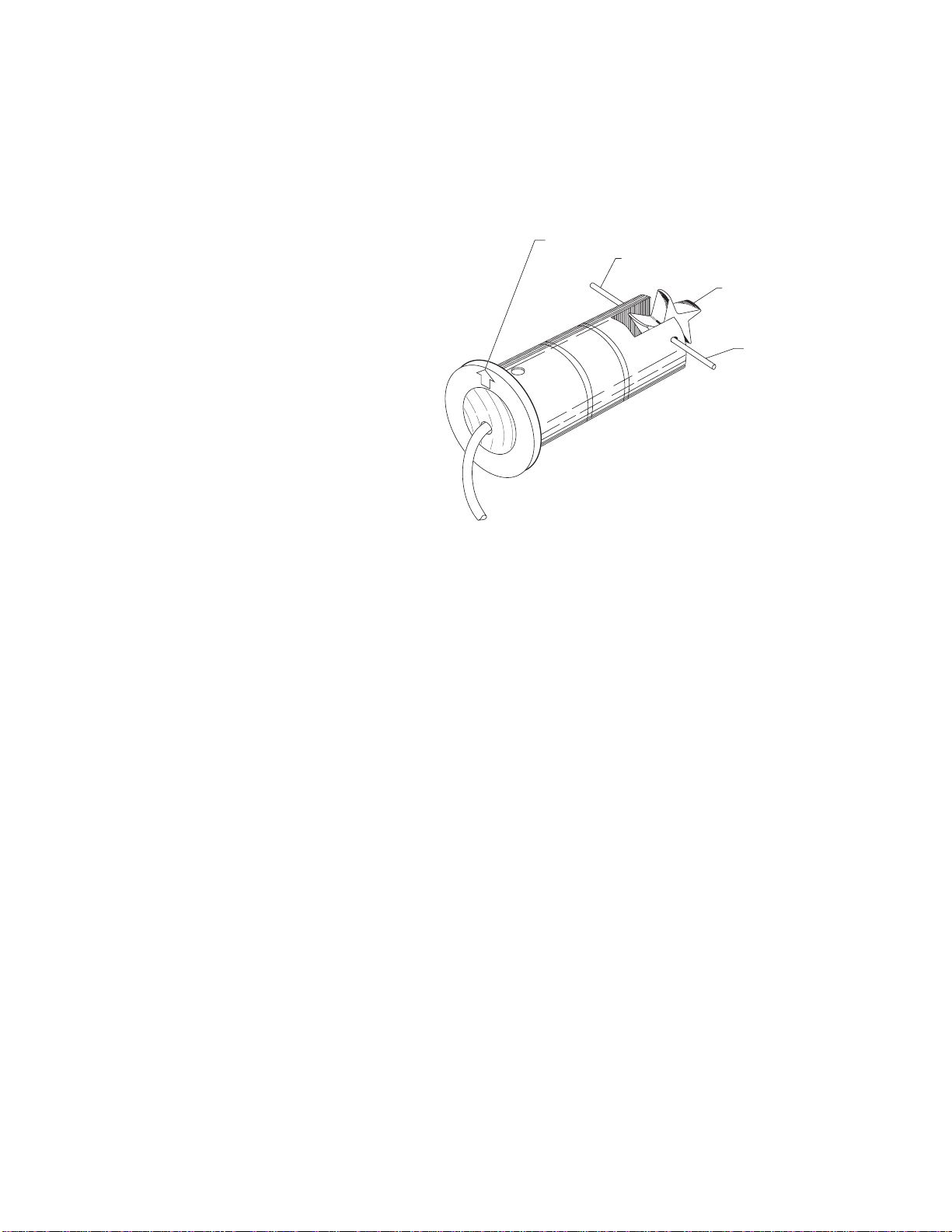
7) Refer to Figure 1. To reinstall, position the impeller in the cavity oriented as in Step 4 so that the impeller
blades point into the flow direction. The flow direction arrow on the top of the sensor housing should point
downstream with the impeller blades pointing upstream.
8) Carefully push the shaft through the housing and impeller, taking care not to damage bearings. Make sure
that the shaft is inserted far enough so that it clears the housing on each side of the impeller housing.
NOTE: If shaft is not carefully installed, the bearing can be deformed, preventing free rotation.
9) Inspect the O-rings for damage and replace as necessary. Clean the O-rings and the sleeve and relubricate
with silicone grease from the packet provided, or use some other acceptable lubricant.
10) Install the sensor into the tee so the flow arrows points in the direction of the actual flow.
11) Install or replace the clevis pin.
13) This completes the replacement procedure. The system may now be repressuri ed and tested.
NOTE DIRECTION OF ARROW
USE PLIERS HERE
NOTE DIRECTION OF
IMPELLER
USE METAL PIN TO
REMOVE CERAMIC SHAFT
Figure 1
Impeller Assembly and Shaft Replacement

Data Industrial Plastic Tee Type Flow Sensor Manual
8
Temperature (°C)
Pressure (psi)
0
20
40
60
80
100
02560
220PV
PRESSURE/TEMPERATURE DIAGRAMS FOR
DATA INDUSTRIAL FLOW SENSORS
Specifications
Wetted Materials (except tees)
See Ordering Matrix
Tee for 22 PV
Schedule 80 PVC per ASTM D-2462 and D-2467.
Virgin, unplastici ed PVC resin, Type 1 cell classifi-
cation
12454-B. Fittings and solvent carry approval for
potable water by NSF and IAMPO.
Pressure, Temperature Ratings
Depends on hardware configurations. See Dia-
grams at end of this section.
Recommended Design Flow Range
½ to 30 ft/sec
Accuracy
± 1.0% of full scale over recommended design flow
range
Repeatability
± 0.3% of full scale over recommended design flow
range for 228PV
Linearity
± 0.2% of full scale over recommended design flow
range for 228PV
Transducer Excitation
Quiescent current 600uA@8VDC to 35VDC max.
Quiescent voltage (Vhigh)
Supply Voltage -(600uA*Supply impedance)
ON State (VLow) Max. 1.2VDC@40mA current limit
(15ohm+0.7VDC)
Output Frequency
3.2 H to 200 H for all except 228PF
Output Pulse Width
5 msec ±25%
Electrical Cable for Standard Sensor Electronics
20 feet of 2-conductor 20 AWG shielded U.L. type
PTLC wire provided for connection to display or
analog transmitter unit. Rated to 105°C. May be
extended to a maximum of 2000 feet with similar
cable and insulation appropriate for application.
Electrical Cable for IR Sensor Electronics
48 inches of U.L. Style 116666 copper solid AWG
18 wire w/direct burial insulation. Rated to 105°C.

Data Industrial Plastic Tee Type Flow Sensor Manual
9
Troubleshooting
1) If the voltage at the sensor input is less than 7 VDC in a No Flow situation, disconnect the sensor from the
barrier strip and measure the voltage at the sensor input terminals of the barrier strip again. It should be
between 8 VDC and 20 VDC. If the voltage at the sensor input is still below 7 VDC or 3 VDC, the problem
may be with the monitor (hardware or programming).
2) If you suspect that the sensor is bad, you can test the monitor circuitry by connecting a piece of wire to
one of the sensor input terminals and tap the other side of the wire to the other sensor input terminal.
Shorting across the sensor input terminals ON and OFF repeatedly allows the display to respond by trying
to calculate a flow rate for the frequency of your shorting action. If the display does not show a change
from 0.00, it indicates a problem with the monitor.
3) If the monitor tests ok and there are any splices in the cable, break the sensor cable at the splice closest
to the sensor and retry the shorting test in step 2.
4) If the cable tests ok, drain the pipe line, verify the pressure is off, and pill the clevis pin holding the sensor
electronics. Spin the impeller by hand. If flows are noted on the display, and impeller spins freely then the
flow rates may have been below our design minimums or the line was full of air. Try again. If the sensor
fails to respond then replace sensor.

Data Industrial Plastic Tee Type Flow Sensor Manual
10
All rights reserved. No part of this work covered by the copyrights hereon may be reproduced or copied in any
form or by any means - graphic, electronic, or mechanical, including photocopying, recording, taping, or informa-
tion and retrieval systems - without written permission of Data Industrial.
Copyright © 2002
Data Industrial Corporation
11 Industrial Drive
Mattapoisett, MA 02739
TEL: 508-758-6390 FAX: 508-758-4057
www.dataindustrial.com
email: [email protected]
Warranty
Data Industrial Corporation (Seller) of 11 Industrial Drive, Mattapoisett, Massachusetts 02739-0740, U.S.A.,
warrants to the original purchaser of its product that such product manufactured by Data Industrial Corporation shall
be free from defects in materials or workmanship when installed, serviced and operated according to Data Industrial
corporation instructions or in other such normal use. This warranty is effective for a period of 12 months from the
date of installation by the Purchaser or 18 months from the date of shipment by the Seller whichever occurs or
terminates first. This limited warranty does not cover damage or loss resulting from corrosion or erosion caused by
acids or other chemicals or by severe environmental conditions or negligent or improper installation or improper
operation, misuse, accident, unauthori ed repair or substitution of components other than those provided by the
Seller, and does not cover limited life components such as bearings, shafts, impellers where wear rate is a function
of application and environment. Any component not manufactured by the Seller but included in its products shall
not be covered by this warranty and is sold only under such warranty as the manufacturer may provide.
If Buyer or Purchaser wishes to make a claim hereunder, he shall send written notice of any defect within the warranty
period, to Seller at the above address. Seller may at its sole option instruct Buyer to ship subject part, postage
prepaid, to the Seller at above address or authori e a representative to inspect the part on site. Seller will at its
sole option repair or replace any defective product covered by this warranty. If Buyer makes repairs or alterations
to any product or part covered by this warranty without Sellers prior written approval, this warranty shall be null and
void.
The foregoing shall constitute Buyers or Purchasers sole and exclusive remedy against Seller, and no other
remedy, including but not limited to, incidental or consequential damages for personal injury, loss of fluids, gases
or other substances or for loss of profits or injury to property or person shall be available to the Buyer or Purchaser.
The warranty extended herein shall be in lieu of any other implied warranty of merchantability or fitness for a particular
purpose, and seller shall bear no liability for representatives or retail sellers. In no event shall Data Industrial
Corporation be liable for any contingent, incidental, or consequential damage or expenses due to partial or complete
inoperability of its product.
This manual suits for next models
4
Table of contents


