Data-Linc Group MDL500/MR User manual

USER GUIDE
I
NDUSTRIAL
D
ATA
C
OMMUNICATIONS
It is essential that all instructions contained in the User Guide are followed precisely to ensure proper operation of equipment.
Two-Wire and Four-Wire
Private Line FSK Modems
Full and Half-Duplex Operation
MDL500/MR
MDL500/LR

DATA-LINC GROUP
PN 161-10003-002B
Product User Guide

DATA-LINC GROUP
1
MDL500 User Guide
PN 161-10003-002B
rev 8/03
Table of Contents Page
Introduction 3
Transmission 3
RS232 Interface 3
MDL500 Master Unit 3
MDL Remote Units 3
Power Source 4
Operating Modes 4
Installation 4
Field Configuration Procedure 5
Operation 5
Jumper Settings 6
DCE and DTE Settings 6
Trasmitter Output Level 6
Receiver Gain 6
Carrier Detect 7
Chassis Ground 7
Half-Duplex Operation/Carrier Control 7
Special Instructions 8
MDL500/MR/LR Four-Wire Long Range Transmitter & Receiver Jumpers 8
MDL500/MR/LR Four-Wire Long Range Carrier Signal Connectors 8
Front Panel LEDs 8
General Operating Notes 9
Non-Loaded Transmission Line 9
Loop Back Test 9
AE485Interface 9
Technical Specifications 10
Technical Support 11
Product Warranty 11
ReturnMaterialAuthorization 11
Contact Information 11
AppendixA 12
○○○○○○○○○○○○○○○○○○○○○○○○○○○○○○○○○○○○○○○○○○○○○○○○○○○○
○○○○○○○○○○○○○○○○○○○○○○○○○○○○○○○○○○○○○○○○○○○○○○○○
○○○○○○○○○○○○○○○○○○○○○○○○○○○○○○○○○○○○○○○○○○○○○○
○○○○○○○○○○○○○○○○○○○○○○○○○○○○○○○○○○○○○○○○○○○○
○○○○○○○○○○○○○○○○○○○○○○○○○○○○○○○○○○○○○○○○○○○○○
○○○○○○○○○○○○○○○○○○○○○○○○○○○○○○○○○○○○○○○○○○○○○○○○
○○○○○○○○○○○○○○○○○○○○○○○○○○○○○○○○○○○○○○○○○○○○○○
○○○○○○○○○○○○○○○○○○○○○○○○○○○○○○○○○○○○○○○○○○○○○○○○○○○○
○○○○○○○○○○○○○○○○○○○○○○○○○○○○○○○○○○○○○○○○○○
○○○○○○○○○○○○○○○○○○○○○○○○○○○○○○○○○○○○○○○○
○○○○○○○○○○○○○○○○○○○○○○○○○○○○○○○○○○○○○○○○○○○○○○○○○○○○○
○○○○○○○○○○○○○○○○○○○○○○○○○○○○○○○○○○○○○○○○○○○○○○○○
○○○○○○○○○○○○○○○○○○○○○○○○○○○○○○○○○○○○○○○○○○○○○○○○○
○○○○○○○○○○○○○○○○○○○○○○○○○○○○○○○○○○○○○○○○○○
○○○○○○○○○○○○○○○○○○○○○○○○○○○○○○○○○○○○○○○○○○○○○○○○
○○○○○○○○○○○○○○○○○○○○○○○○○○○○○○○○○○○○○○○○○○○○○○○
○○○○○○○○○○○○○○○○○○○○○○○○○○○○○○○○○○
○○○○○○○○○○○○○○○○○○○○○○○○○○○○○○○○○○○○○○○○○○○○○○○
○○○ ○○○○○○○○○○○○○
○○○○○○○○○○○○○○○○○○○○○○○○○○○○○○○○○○○○○○○○○○○
○○○ ○ ○ ○○○○○○○
○○○○○○○○○○○○○○○○○○○○○○○○○○○○○○○○○○○○○○
○○○○○○○○○○○○○○○○○○○○○○○○○○○○○○○○○○○○○○○○○○○○○○○
○○○○○○○○○○○○○○○○○○○○○○○○○○○○○○○○○○○○○○○○○○○○○○○○○
○○○○○○○○○○○○○○○○○○○○○○○○○○○○○○○○○○○○○○○○○○○○○○○○
○○○○○○○○○○○○○○○○○○○○○○○○○○○○○○○○○○○○○○○○○○○○
○○○○○○○○○○○○○○○○○○○○○○○○○○○○○○○○○○○○○○○○○○○○○○○○
○○○○○○○○○○○○○○○○○○○○○○○○○○○○○○○○○○○○○○○○○○○○○○○○○○○○
○○○○○○○○○○○○○○○○○○○○○○○○○○○○○○○○○○○○○○○○○○○○○○○
○○○○○○○○○○○○○○○○○○○○○○○○○○○○○○○○○○○○○○○○○○○○○○○○
○○○○○○○○○○○○○○○○○○○○○○○○○○○○○○○○○○○○○○○○○○

DATA-LINC GROUP
2PN 161-10003-002B
rev 8/03
MDL500 User Guide

DATA-LINC GROUP
3
MDL500 User Guide
PN 161-10003-002B
rev 8/03
Introduction
TheData-LincGroupMDL500/MRis atwo-wire privatelinemodem.TheMDL500/MRallows 9600 baud full and half-duplex
RS232data communications over a single dedicated wirepair and acrosssliding contacts. TheMDL500/MR operates using
pure Frequency Shift Key (FSK) at high carrier frequencies (100 KHz, 106.5 KHz to 150 KHz, 156.5 KHz) making the
MDL500/MRparticularly immune to cross-talkand outside noise interference.This provides highlyreliable,continuous data
transmissionoverdistances of several milesin harsh industrial environments.
TheData-LincMDL500/LRis a four-wire private line,longrange9600baud full-duplex modem. In fourwireLRoperation, the
typical range on 22 gauge communication wire is 8 to 10 miles.
Transmission
TheMDL500performsdata communication by converting digitalsignalstomodulatedhigh frequency sine-wave carrier
signals that can be transmitted much longer distances with greater noise immunity on wires than square wave digital
signals.The digitalSpace and Mark (or 0 and 1) are converted in thetransmitter tocarrier signals having two slightly different
frequencieswhichare identified bythereceiver and reconvertedtothe digital signals.TheMDL500s are eitherMasteror
Remoteunits and can beused for eitherpoint-to-point or multi-pointcommunications. The MDL500s areasynchronous serial
datacommunication devices, data ratetransparent from DC to9600 baud.
In multi-drop installations, the modems can be connected in a star or daisy-chained. The master modem can be located at
any of the connection points.
RS232 Interface
TheMDL500connects to the userprovided equipment via anindustry standard, female DB25connectorconforming to the
IEEERS232C standard. The modem can be configuredto function aseither a DCEor DTE interface.
Data-LincGroupprovides cables and/orpinoutsfor connecting theMDL500to a widevarietyof electronic devices.Contact
our technical support staff for cable specifics.
MDL500 Master Units
TheMDL500 Master unittransmitsat 106.5/100 KHz(Space/Mark) and receivesat 156.5/150 KHz.Apluggabletwo position
terminal block at the back of the unit is used for non-polarized connection to the transmission line.
MDL500 Remote Units
The MDL500 Remote unit transmits at 156.5/150 KHz and receives at 106.5/100 KHz. It has the same data line connector
as the Master unit.

DATA-LINC GROUP
4PN 161-10003-002B
rev 8/03
MDL500 User Guide
Power Source
The MDL500 is powered by nominal 24 volts DC which is supplied to a black barrel jack on the rear panel. The units are
deliveredfrom the factory with 120 VAC to24 DC wall transformers, whichhave a blackplug attached.Anexternal 24 VDC
supply can also be used to power the MDL. The current draw is 250 mA.
Caution: Ensuretheunit is disconnected frompowerbefore removing the cover.
Operating Modes
TheMDL500 can be operatedin either point-to-pointor multi-point polling modes.In point-to-point, themodems can be
operatedinfull-duplex.
For multi-point data communications, the MDL500 can be operated with one Master and up to eight Remote units. The
connected intelligent device controls the transmitter in each Remote unit. The Master unit’s transmitter remains on at all
time; however, only one slave transmitter can be active at any given time. Multi-point systems must e operated in a half-
duplexmode.
Forfourwire MDL500 operation,seethe section onMDL500/MR/LR Four-Wire SpecialInstructions.
Installation
TheMDL500 factory configurationis set for fullor half-duplex point-to-point operationwith P4 inthe B-C position.The Master
andRemote units areboth factory configuredas DCEs (DataCommunications Equipment) with the jumpers on headers P1
and P2 in the B-C position. Data into the DB25 is on pin 2 and data out is on pin 3. (Also see section 5.0, entitled Jumper
Settings.)
Prior to installation, it is important to ensure that the digital devices to be connected to the MDL500/MR units are capable of
communicatingwith each otheras if connectedwith a conventional three-wire RS232 data cable. Oncethis has been
established, the devices can be connected to the MDL500/MR units and RS232 data communications will take place
transparently.
Note: It is important the wire pair to be used for data communications between the MDL500/MR units:
a) Is connected only to those units.
b) Has no branches and no attached inductance, capacitance or resistance.
c) Has no loading coals, filters or any other load.
d) And all connections must be clean and solid.
Note: Since the data line is transformer isolated from the rest of the circuit, neither leg of the data carrying twisted pair
shouldbegrounded.

DATA-LINC GROUP
5
MDL500 User Guide
PN 161-10003-002B
rev 8/03
Field Configuration Procedure
Thefieldconfigurationprocedure is as follows:
1. Removethe unit’s cover byremoving the fourscrews on top ofthe modem.
2. SettheRemote units foreither full orhalf-duplex operation bypositioning the jumperon header P4,located behind
theDB25 connector.Forfull-duplex operation, the jumper should be inthe B-C position;for half-duplex, multi-point
operation using RTS line carrier control, the jumper should be in theA-B position.
3. Confirm that the jumpers on locations P1 and P2 are in the B-C position.
4. Replace the cover.
5. ConnecttheRS232 communications port of theDataTerminal Equipment (DTE) (PC, PLC,etc.) to theMDL500
unitwithan appropriate cable.
6. Connect the transmission line to the unit at the pluggable terminal block. There is no polarity requirement.
Connect the unit’s power cord to the barrel jack in the rear panel of the modem and plug the modular transformer into a
convenient 120VAC outlet. Plugging the power in will power up the units; there is no “On/Off” switch.
Operation
Point-to-point, full or half-duplex operation is usually conducted with the both the Master and Remote MDL carriers on all the
time. This is achieved by placing the P4 jumper in the B-C position, which causes the MDL to ignore the RTS line.
In half-duplex, multi-drop, operating mode, with the P4 jumper in theA-B position, the RTS line of the intelligent device that a
Remote MDLis connected to (PC, PLC or RTU) is used to control the MDL’s transmitted carrier. When logic low, the carrier
is turned off; when logic high, the carrier is turned on. If the RS232 cable is disconnected, the RTS connection on the MDL is
biased low and the carrier remains off. (If the P4 jumper is in the B-C position, the RTS connection is biased high and the
carrier will stay on.)
Whenproperly configured, the MDL500 is capableof half orfull-duplex data transmission atrates up to 9600 baud.MDL’s
require no settings for data rate and will operate transparently as data is fed to them. They will begin communicating data as
soonas connections aremade and they are powered up.

DATA-LINC GROUP
6PN 161-10003-002B
rev 8/03
MDL500 User Guide
Jumper Settings
Thereare several configuration optionsthat can beselected by jumpers asdescribed below.The jumperpins are internal and
areidentified bylettering onthe circuitboard. Jumperpins are accessed by removing the four retaining screws on the top
coveroftheenclosureandremovingthecover.
Note: The header position locations are described with the MDL board oriented with the LED’s to the left and the
connectors to the right.
DCE and DTE Settings
Boththe MDL500 Masterand Remote unitsare configured at the factory as DCE (Data Communication Equipment)for
connection to DTE (DataTerminal Equipment). APC, PLC or Multiplexer is usually configured as DTE. If either the Master or
Remote DTE/DCE must be changed, this is accomplished by moving the jumpers on blocks “P1” and “P2” which are located
directly behind the DB25 RS232 connector on the rear panel. For example, as delivered, the Master unit P1 and P2 jumpers
are both set in the B-C position (DCE setting). To change to a DTE, move both jumpers to theA-B position. In DTE, data
into the DB25 will be on pin 3 and data out on pin 2.
Transmitter Output Level
TheMDL500 allows theselection of eitherNormal or HighPower (HP) transmitteroutput. The High Power output has six
timesgreaterpeak-to-peak transmitted signalandprovides correspondingly greater signalto noise ratio. HighPower
transmitteroperationis generally preferred inapplications involving sliding contactsorin very noisyEMIenvironments.
However, caution is advised in some cases since High Power carrier signals will result in more cross-talk to adjacent
conductors.
The jumper to select Normal or High Power is located at position TP2. High Power is selected when the jumper is positioned
center to left; Normal output is selected with center to right. When using the HP setting, the receiver gain should be set to
low. (See Receiver Gain below.) The factory setting is Normal, center to right.This header is positioned slightly below the
TOKOCoilmarked“T5.”
Receiver Gain
The MDL500incorporates a receiveramplifier on thecircuit board.Thisamplifier has low,normal andhigh gain settings
configured by a “T” shaped pin block near the center of the circuit board with pins marked “G1,” “G2” and “G3” (the leg of the
“T”). G1/G2 is the high gain setting; G2, the normal medium gain; and G3/G2, the low gain. The units are delivered from the
factory set at normal gain because the transmitter has been factory set at normal output. The low gain setting should be
usedon the receiver wheneverthe high powertransmitter option isselected on the transmitterto avoid onboardcross-talk.

DATA-LINC GROUP
7
MDL500 User Guide
PN 161-10003-002B
rev 8/03
Carrier Detect
The Carrier Detect signal to the RS232 connector is enabled or disabled by Jumper Matrix P3. The MDL units are shipped
withtheCarrier Detect enabled (jumperon).
Chassis Ground
Chassisground canbe connectedto signalground viaJumper P5.This is generally not recommended.Aseparate chassis
ground wire may be connected to the MDL’s metal enclosure by means of any of the cover mounting screws as desired to
avoida possible shock hazard.
Half-Duplex Operation/Carrier Control
TheMDL500can be operated inmulti-drop/half-duplex mode by controllingthetransmitter’s carrier on/off usingexternal
signals. The most common external carrier control signal is through the RS232 port RTS line (pin 4). Jumper P4,A-B,
selects this line. When an external RTS logic high is asserted, the MDL carrier is turned on, and a logic low or ground,
turns the carrier off. The MDL RTS line is biased low so that if the RS232 cable is disconnected or the external controlling
device is turned off, the carrier will go off. Selecting jumper P4, B-C, turns the transmitter on and blocks RTS carrier control.
TheB-C settingis usedin full-duplexoperation. Usuallyonly theRemote units have their carriers controlled by the devices
they are connected to (settingA-B). The Master unit’s carrier is left on all the time (setting B-C). (There is no interference
sincethe Master andRemote carrier frequenciesare different.) Thefactory setting forboth MDL Mastersand Remotes is
P4,B-C,for full or half-duplex,point-to-pointoperation.

DATA-LINC GROUP
8PN 161-10003-002B
rev 8/03
MDL500 User Guide
MDL500/MR/LR Four-Wire Special Instructions
Thestandardinstruction “MDL500 IndustrialModemHalf and Full-Duplex Versions”areapplicable with the following
modifications:
MDL500/MR/LR Four-Wire Long Range Transmitter & Receiver Jumpers
The transmitter output is set to high by placing the jumper located on the three pin mail header marked “TP2” in the left and
center position (left side on the marking TP2). The receiver gain is set on medium by placing the jumper on the four pin male
header(invertedT-shape)located aboveT5and C35 on the bottom center(markedG2)and pin between R53 andR55.
Note: The header position locations described are with the MDL board oriented with the LED’s to the left, the
connectors to the right.
MDL500/MR/LR Four-Wire Long Range Carrier Signal Connectors
Thefour-wire MDL hasa second I/Oisolation coil and a second two-position pluggable terminalblock for thetransmitted
carrier. Facing the connectors, the pluggable terminal block on the left is the transmitted carrier and the pluggable terminal
block on the right is the received carrier.
Forproper operation, both modemsmust be setto the samefour-wire configuration.
Front Panel LEDs
Thereare four LED’s on the front panel of the MDL. From left toright:
The first diagnostic LED is Carrier Detect. In full-duplex mode, the CD LED must be lighted on both units. In half-duplex
operation with the Master carrier on and the carrier control mode with RS232 cables connected, the CD LED will be lighted
onall RemoteMDL500/MR’s andOFF on the Master MDL500/MR. (The Master CD LED will blink during operation as each
Remote MDL500/MR turns on its carrier to answer back to the Master). If the correct CD LED’s are not ON, a carrier cable
problem is likely.
Assuming that the CD indication is correct, a Loop Back test is recommended as described on the next page.
gnikraM noitcnuF
DCtceteDreirraC
XRtrop232-SR005LDMehtfotuogniwolfataD
XTtrop232-SR005LDMehtotnigniwolfataD
RWPdetcennoCrewoP

DATA-LINC GROUP
9
MDL500 User Guide
PN 161-10003-002B
rev 8/03
General Operating Notes
TheMDL500/MR utilizes tuned circuitsto achieve highperformance. These circuits havebeen carefully adjustedat the
factoryto operate overseveral miles of transmission line. In order notto degrade performance,it is important not todisturb
these adjustments. In particular, coilsT1, T2,T3, T4 and T5 and potentiometers R18, R20, R31 and R57 should not be
adjusted.If these adjustmentshave been inadvertently changed,please contact the factory.
Non-Loaded Transmission Line
Properoperationof MDL500/MR requiresthatthe transmission linebenon-loaded (free frominductorsand capacitors on the
line). The presence of inductors, capacitors or excessive resistance (i.e., bad connections) or shorts between the wires can
seriouslydegradeperformanceorrender the data transmission inoperable.
Loop Back Test
ALoop Back testis suggested to confirm the proper operation ofMDL500/MR’s in point-to-pointoperation, as follows:
APC running acommunication program infull-duplex can be connected to one of the MDL500/MR’S ina point-to-point
configuration.Ajumper wire (a bent paper clip works very well) is placed between pin sockets 2 and 3 of the DB25 on the
other MDL500/MR. Data sent to the first MDL500/MR will be looped back from the second and appear on the PC screen. If
thecharacters are correct, theMDL500/MR’s are functioning.
AE485 Interface
TheMDL500 is also availablewith an RS485 interfacefor connection tomultiple Remote devices.Alloperatingfunctions and
instructionsare the same as forthe RS232 full-duplex version, exceptthat the digital interface throughthe DB25 connector
uses pin 12 as the -DO/RI connection and pin 13 as the +DO/RI connection. The RS232 connections (pins 2, 3 and 7) are
notfunctional.
Note: Do not connect anything except an RS485 signal to positions 12 and 13 on the DB25 or damage
to the circuit could occur.
TheData-LincGroupAE485 (Auto Enable) circuitcontainsa special feature that eliminates the needfor a separateenable
signalor lineto command the 485 transmit and receive functions. Data will pass through the MDL500 RS485 port
transparentlyineither direction. The MDL500sareoperated in full-duplex point-to-pointmode(no carrier control) whenusing
theAE-485 interface.Up to 32Remote RS485 devicescan be multi-droppedofftheMDL500AE485port at distancesof up
to 4000 feet and at data rates of 9600 baud.A100 ohm termination resistor should be connected at the ends of the 485 line.

DATA-LINC GROUP
10 PN 161-10003-002B
rev 8/03
MDL500 User Guide
Technical Specifications
tamroFataD )lanoitpo584/224-SR(C232-SR
noitarepO atadsuonorhcnysa,reirracdellortnocxelpudflahroxelpudlluf,eriw2
edoMnoitpopord-itlumrotnioPottnioP
deepSnoissimsnarTataDduab0069otpU
noitaludoM yleviticapacdnaylevitcudnilangisreirrac;)KSF(yektfihsycneuqerF
detalosi
ecnatsiDriapdetsiwtelgnisnoteef000,84otpU
erutarepmeTgnitarepO23
0
041-
0
0(F
0
06-
0
)C
stnemeriuqeRrewoPCDV42
ecafretnI
;C232-SRrofrotcennoc52BDelameF;elbatcelesrepmujECD/ETD
mm5.5xmm5.2;reirracrofkcolblanimretelbaggulpnoitisopowt
.rewopCDV42rof)evitisopretnec(kcajlerrab
srotacidnIDEL rewoP,ataDtimsarT,ataDevieceR,tceteDreirraC
snoisnemiD ;)Lmc76.62xWmc50.91xHmc54.4(L"5.01xW"5.7xH"57.1
.tniapecnahteruylop;leetseguag61,erusolcnelatemlla

DATA-LINC GROUP
11
MDL500 User Guide
PN 161-10003-002B
rev 8/03
Technical Support
Data-LincGroupmaintains a fully trained staffofservice personnel who arecapableofproviding complete product
assistance.They can provideyou with technical,application and troubleshooting,spare parts and warranty assistance.
Ourtechnical staff isbased in Bellevue,Washington USA andmay be reachedat (425) 882-2206or e-mail
Product Warranty
Data-LincGroupwarrants equipment ofitsown manufacture to befree from defects inmaterial and workmanship forone
yearfrom dateof shipmentto originaluser.Data-LincGroup will replace or repair, at our option, any partfound to be
defective.Buyermust return any partclaimeddefective to Data-Linc Group,transportation prepaid.
Return Material Authorization
If a part needs to be sent to the factory for repair, contact Data-Linc Group’s corporate office and request a Return Material
Authorization(RMA) number.The RMAnumberidentifiesthe part and the owner and must be included withthe partwhen
shipped to the factory.
Contact Information
Corporate Office Data-Linc Group
3535Factoria Blvd. SE
Suite100
Bellevue,Washington98006USA
Telephone:(425)882-2206
Fax:(425) 867-0865
E-mail:[email protected]
Website: www.data-linc.com

DATA-LINC GROUP
12 PN 161-10003-002B
rev 8/03
MDL500 User Guide
Appendix A
Diagrams
Diagram 1
Drawingofthe two-wire MDL500/MRenclosuredepicting the locationofconnectors and LEDs.
Diagram 2
Schematic of the RS232 port with pin functions and pinout.
RS232 Pin
Assignment Description Signal Direction
1 ProtectiveGround Computer ↔↔
↔↔
↔modem
2 ReceiveData Computer →→
→→
→modem
3 TransmitData Computer ←←
←←
←modem
4 Requestto Send Computer →→
→→
→modem
5 CleartoSend Notconnected
6 DataSet Ready Not connected
7 SignalGround Computer ↔↔
↔↔
↔modem
8 CarrierDetect Computer ←←
←←
←modem
20 DataTerminalReady Notconnected
MDL500 rear
+24 VDC FSK RS-232
MDL500
CD RxD TxD PWR
MDL500 front
13 12 11 10 9 8 7 6 5 4 3 2 1
25 24 23 22 21 20 19 18 17 16 15 14

DATA-LINC GROUP
13
MDL500 User Guide
PN 161-10003-002B
rev 8/03
Diagram 3
Illustrationofa typical full-duplexandhalf-duplex, multi-drop applicationconnections.
Diagram 4
MDL500/MRtwo-wire boardlayout illustrating Jumper settings and test points. (Not to scale.)
This manual suits for next models
1
Table of contents
Other Data-Linc Group Modem manuals

Data-Linc Group
Data-Linc Group DLM4100 User manual
Data-Linc Group
Data-Linc Group DLM4000 User manual
Data-Linc Group
Data-Linc Group LCM100 User manual
Data-Linc Group
Data-Linc Group SRM6200E-SLC User manual

Data-Linc Group
Data-Linc Group FLC910E User manual

Data-Linc Group
Data-Linc Group PlantLinc PLR5000 User manual
Data-Linc Group
Data-Linc Group DLM4500 User manual
Data-Linc Group
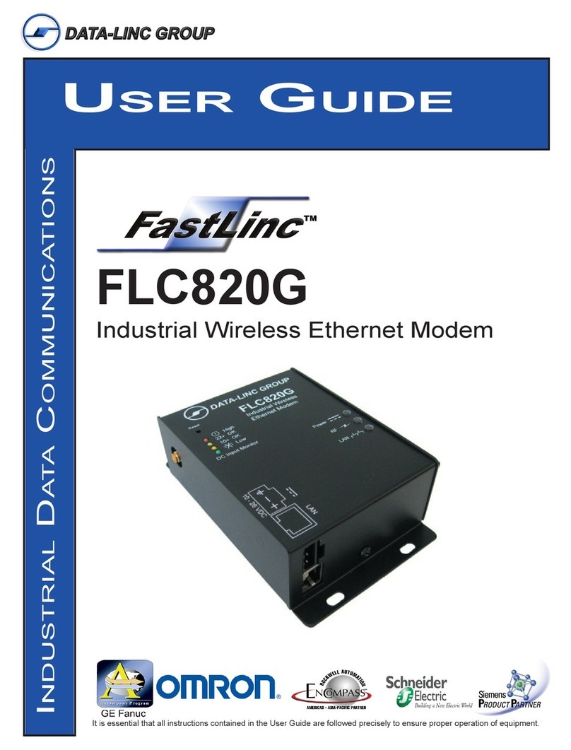
Data-Linc Group FastLinc FLC820G User manual
