Data Video AM-100 User manual


- 2 -
Warranty
Standard Warranty
•Datavideo equipment is guaranteed against any manufacturing defects for one year from the date of purchase.
•The original purchase invoice or other documentary evidence should be supplied at the time of any request for
repair under warranty.
•Damage caused by accident, misuse, unauthorized repairs, sand, grit or water is not covered by this warranty.
•All mail or transportation costs including insurance are at the expense of the owner.
•All other claims of any nature are not covered.
•Cables & batteries are not covered under warranty.
•Warranty only valid within the country or region of purchase.
•Your statutory rights are not affected.
Two Year Warranty
•All Datavideo products purchased after 01-Oct.-2008 qualify for a free one year extension to the standard
Warranty, providing the product is registered with Datavideo within 30 days of purchase. For information on how
to register please visit www.datavideo-tek.com or contact your local Datavideo office or authorized Distributors
•Certain parts with limited lifetime expectancy such as LCD Panels, DVD Drives, Hard Drives are only covered
for the first 10,000 hours, or 1 year (whichever comes first).
Any second year warranty claims must be made to your local Datavideo office or one of its authorized Distributors
before the extended warranty expires.
Disposal
For EU Customers only - WEEE Marking
This symbol on the product indicates that it will not be treated as household waste. It must be
handed over to the applicable take back scheme for the recycling of electrical and electronic
equipment. For more detailed information about the recycling of this product, please contact your
local Datavideo office.
Packing List
The following items should be included in the box. If any items are missing please contact your supplier.
1 x AM-100 Audio Mixer
1 x AC Cord
1 x AD Switch DC 12V / 2.5A
1 x AM-100 Quick Start Guide
Introduction
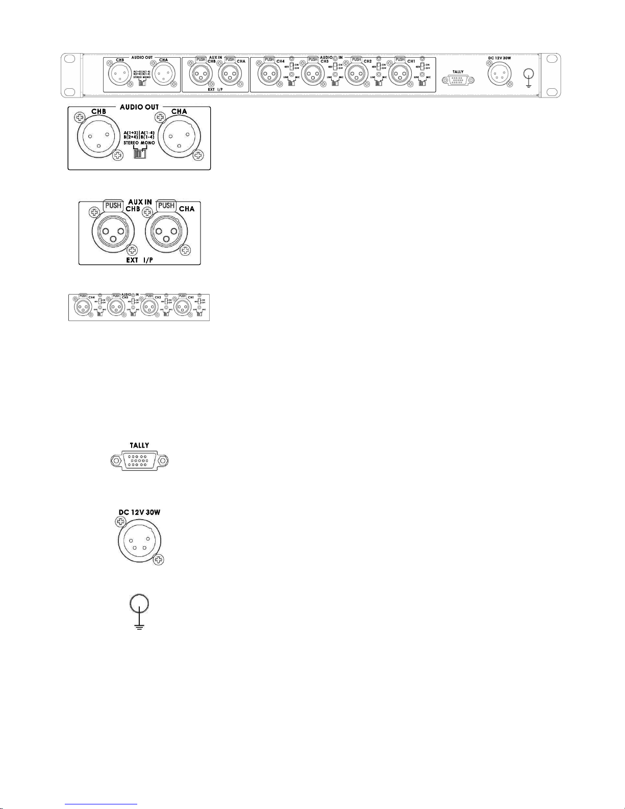
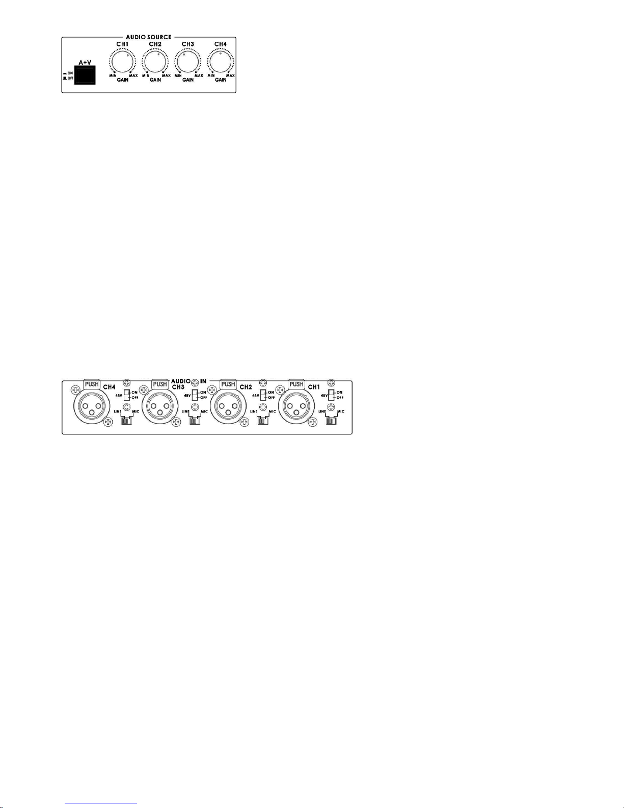
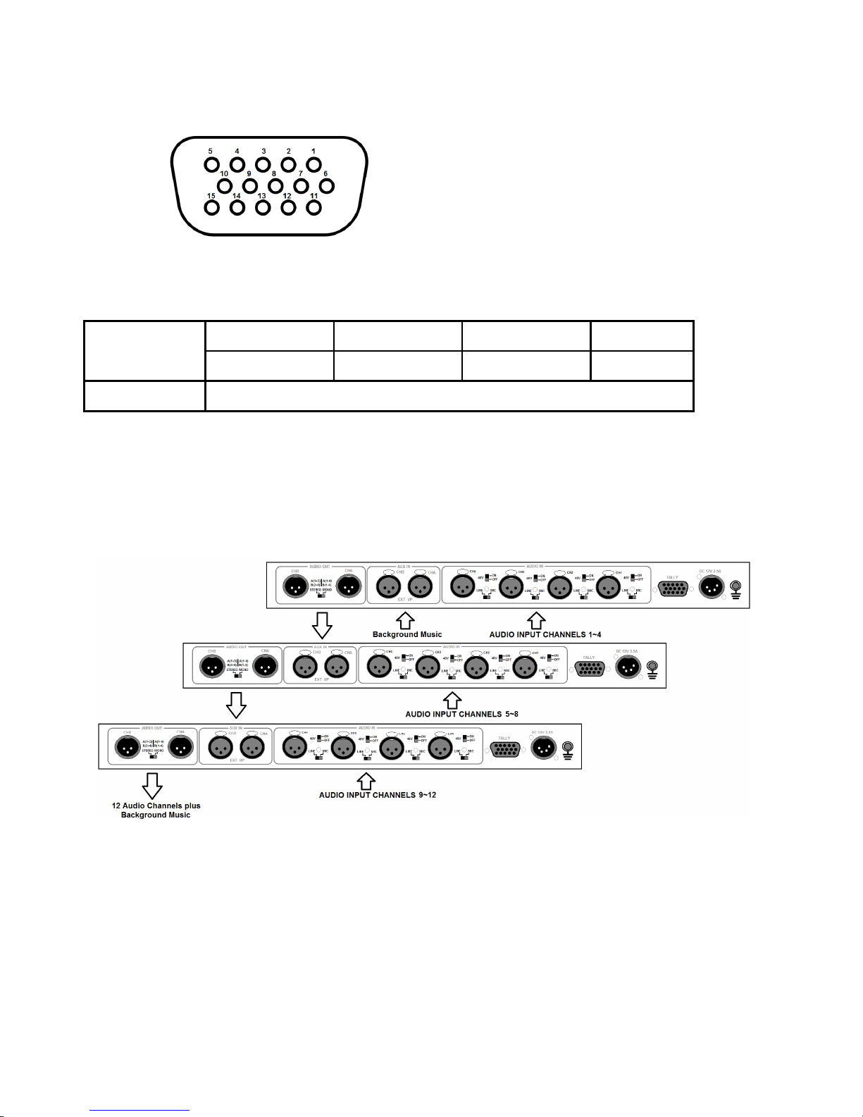
AM-100 is 1U high rack and 5 channel mixer. 1st~4th channel are optional select the Micro-phone or line input. The
5th channel is for secondary AUX XLR input ports. This is a good integration solution of analog audio mixer.
The major feature is audio-follow- video. AM-100 can be applied for OB Van and SE-900.
SE-900 on audio only has audio delay function, not provides simultaneous audio follow video switching function as
SE-2000 or SE-800 do. For this demand, Datavideo provides AM-100 to work with SE-900 on this solution.
AM-100 is a 4 x XLR input, 2 x AUX XLR input & 2 x XLR output audio mixer. This audio mixer can provide SE-900 to
achieve similar function as voice synchronization switching to SE-800 or SE-2000.

- 3 -
Connections & Controls
Front Panel
Power Switch
Switches the power On / Off.
Headphone
Accepts a stereo mini jack plug for stereo headphones. The headphone volume is
adjusted by the rotating Head phone volume control.
Headphone Volume Control
Controls Headphone volume level.
Use the Headphone section to accurately monitor any of the sources output.
Audio LED Meters
These meters play a vital part in correctly setting the audio levels to avoid clipping or
other distortion.
The LED style Audio meters, show the signal strength at the Audio Output. The signal
they measure is determined by the sources selected by the Audio Bus selectors and the
levels set by the rotary pots and faders.
Audio Monitor Button
Use the Headphone section to monitor any of the sources (CH1, CH 2, CH3, CH4) or
“Master” output. Repeated presses of the Headphone Audio Monitor button will cycle
through the monitoring choices. In many cases, headphones may be a more useful and
accurate choice than speakers for audio monitoring.
Audio Input Source Level Controls
This section of the AM-100 controls which audio input channel (CH1~CH4) will be sent
to the Audio Bus and its associated Fader.
This row of audio channel selection buttons has LEDs built in to show which input
channel is active. Level control for each audio input source is via the rotary pots above
each of the audio channel selection buttons.
A+V
When this button is engaged or lit, the audio associated with a selected video input
source automatically follows the video through any transition between the Main and
Sub Sources. When the A+V button is inactive, the audio sources must be switched
manually. For more information, see A+V
AUX Audio Input
Mix input for background music
Audio mixer
These CH1~CH4 Audio Level Faders are for controlling the CH1~CH4 audio mix.
These faders correspond to the Audio Source selector buttons and control the relative
volume of each input in the master output as well as the master output level.
MASTER
This Slider is for controlling the audio level for the Mixed audio output.

- 4 -
Rear Panel
AUX Audio Output
2 channels XLR Balanced Audio output.
AUX Audio Input
Mix input for background music or daisy chaining AM-100 units together. To daisy chain
units together take the AUDIO OUT pair from the first unit and connect these to the AUX
IN on the second unit.
AUDIO IN
The AM-100 supports four XLR Balanced Audio Input channels.
There are two kinds of switches under AUDIO IN:
LINE/MIC switch is used to set the audio as LINE in or MIC in. When LINE in is
selected please also set the 48V ON/OFF switch to OFF in order to prevent burn-out
damage to the circuit.
The 48V ON/OFF switch is for phantom power. If you want to use MIC in, please set the
LINE/MIC switch first, and then if using a Condenser microphone turn ON the 48V
ON/OFF switch. If you wish to use a Dynamic microphone please turn OFF the 48V
ON/OFF switch.
TALLY
TALLY IN socket. This supplies tally source, control output by A+V.
For more information please see the A+V (Page 5).
DC IN – 4pin XLR
DC in socket connect the supplied 12V 2.5A PSU to this socket. The connection can be
secured by screwing the outer fastening ring of the DC In plug to the socket.
Grounding Terminal
When connecting this unit to any other component, make sure that it is
properly grounded by connecting this terminal to an appropriate point. When
connecting, use the socket and be sure to use wire with a cross-sectional area
of at least 1.0 mm2.

- 5 -
A+V
The Audio Input Channel Selectors and Level pots are the first stage in the audio signal path. Each channel carries
the audio associated with a video input channel. When the A+V button is active, the audio follows the video through a
transition. This means that when this LED is lit, only one channel of the Audio input section (CH1, CH2, CH3, CH4)
can be activated at a time. When the transition is a CUT, the audio will switch abruptly at the same time.
Try this: With the A+V button engaged or lit, select Channel 2 on the Main Source bus (of course, you must have a
valid video and audio source connected). Notice that CH2 is lit in the Audio Source section. Now, select channel 1 on
the Sub Source bus. Work the T-Bar to manually perform a transition (if no specific transition is selected, the sources
will dissolve) and watch Audio Input Source channel change from CH2 to CH1, following the video.
When the A+V button is not engaged or off, you can manually select which of the 4 Audio input channels will be
applied to the Video bus at the Fader. In fact, you have to select one or more of these channels, or there will be no
audio present at the audio out connections.
The A+V button should be inactive while doing level settings at the beginning-of-session so that you can select an
input and adjust the initial level correctly.
Audio Inputs and Levels
Analogue audio comes into the AM-100 through the XLR connectors on the rear panel (see above diagram). The AM-
100 supports four XLR Balanced Audio Input channels.
There are two kinds of switches next to each XLR input under AUDIO IN:
The LINE/MIC switch is used to set the audio as LINE in or MIC in. When LINE in is selected please also set the 48V
ON/OFF switch to OFF in order to prevent burn-out damage to the audio circuit/Mic*.
The 48V ON/OFF switch is for Phantom power. If you want to use MIC in, please set the LINE/MIC switch first, and
then if using a Condenser microphone* turn ON the 48V ON/OFF switch. If you wish to use a Dynamic microphone
please turn OFF the 48V ON/OFF switch.
*NOTE: Always double check the manual for the microphone being used to see what advice it gives regarding
power as some Mics have internal batteries too.

- 6 -
Tally Input Connector (A+V feature)
Pin Assignment
The Tally output from a video mixer allows the AM-100 to automatically switch between audio sources in step with the
video mix.
The pin assignment of the Tally Connector is shown in the following table:
CH 1 CH 2 CH 3 CH 4
Audio Channel
Pin 1 Pin 6 Pin 11 Pin 5
GND Pins 4, 9, 14
Example Cascade Set Up
It is possible to cascade or daisy chain several AM-100 units together. This allows more audio sources to be added to
the set up and provided at the final mixed output. To daisy chain units together take the AUDIO OUT pair from the first
unit and connect these to the AUX IN on the second unit. Below diagram shows 3 units connected in this way.
D-Sub 15
p
in Female

- 7 -
Specifications
Specifications are subject to change without notice
Audio Input
Parameter Specification Limit Units Conditions/Comments
MIC/Lin Connectors
(CH1~CH4) 3Pin XLR Female Pin2=(+),Pin3=(-),Pin1=GND
Mic/Lin Input Impedance 3K/5.5K 1% Ω
Mic Gain Range off to +80 ±1.5 dB Audio source GAIN(knob)
Line Gain Range off to +20 ±1.5 dB Audio source GAIN(knob)
Signal to noise ratio -70 min dB @1KHz,0dB(Lin IN)
THD+N 0.06 max % @1KHz,0dB(Lin IN)
Frequency Response 20Hz~20KHz ±3 dB
Lin in Max Level +26dBu ±3% dB
AUX IN
Parameter Specification Limit Units Conditions/Comments
Aux Input (CHA~CHB)
Line Connectors 3Pin XLR Female Pin2=(+),Pin3=(-),Pin1=GND
Lin Input Impedance 45K 1% Ω
Line Gain Range off to +20 ±1.5 dB AUX IN(knob)
Signal to noise ratio -70 min dB @1KHz,0dB
THD+N 0.06 max % @1KHz,0dB
Frequency Response 20Hz~20KHz ±3 dB
Audio Output
Parameter Specification Limit Units Conditions/Comments
Connector 3Pin XLR Male Pin2=(+),Pin3=(-),Pin1=GND
Impedance 300 1% Ω
Gain Range off to +20 ±1.5 dB Audio Mixer(CH1~CH4)(knob)
Output Max Level +26dBu ±3% dB
Headphone
Parameter Specification Limit Units Conditions/Comments
Connector 1/4” TRS Tip(+),Ring=(-),Sleeve=GND
Signal to noise ratio -70 min dB @1KHz,0Db(Lin IN)
THD+N 0.5 max % @1KHz,0Db(Lin IN)
Frequency Response 20Hz~20KHz ±3 dB
Others
Parameter Specification Limit Units Conditions/Comments
Phantom Power +48V ±3% VDC
Power Consumption +12V,1.5A(18W) ±3% watts
Power Input connector 4Pin XLR Male Pin4=(+),Pin1=GND
Dimensions 440X155X4.5 ±1% mm L X W X H

Table of contents
Other Data Video Music Mixer manuals
Popular Music Mixer manuals by other brands

ALLEN & HEATH
ALLEN & HEATH Xone 4D Service manual

Kettler
Kettler Unix P Training and operating instructions

JAKKS Pacific
JAKKS Pacific EZ Pro instruction manual

Behringer
Behringer XENYX X1204USB quick start guide

Louroe Electronics
Louroe Electronics RN-2 Installation and operating instructions

Behringer
Behringer Promixer DX 500 user manual