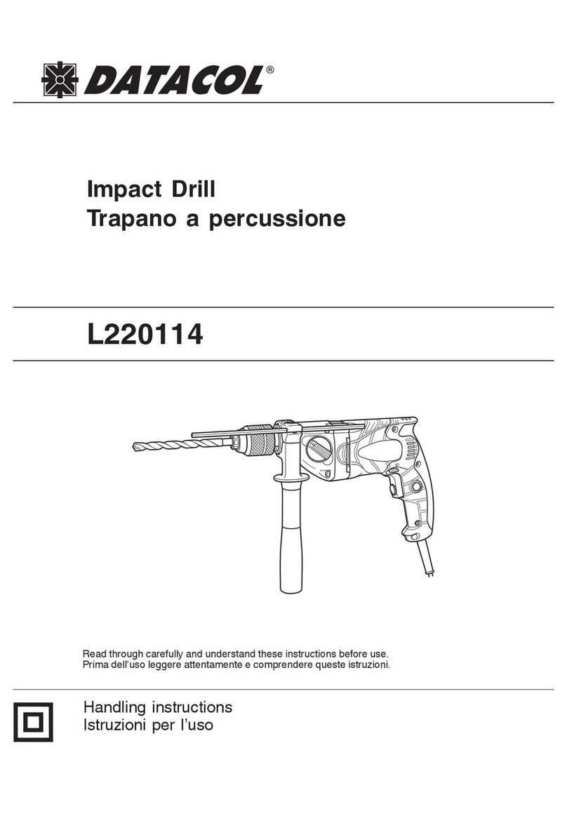
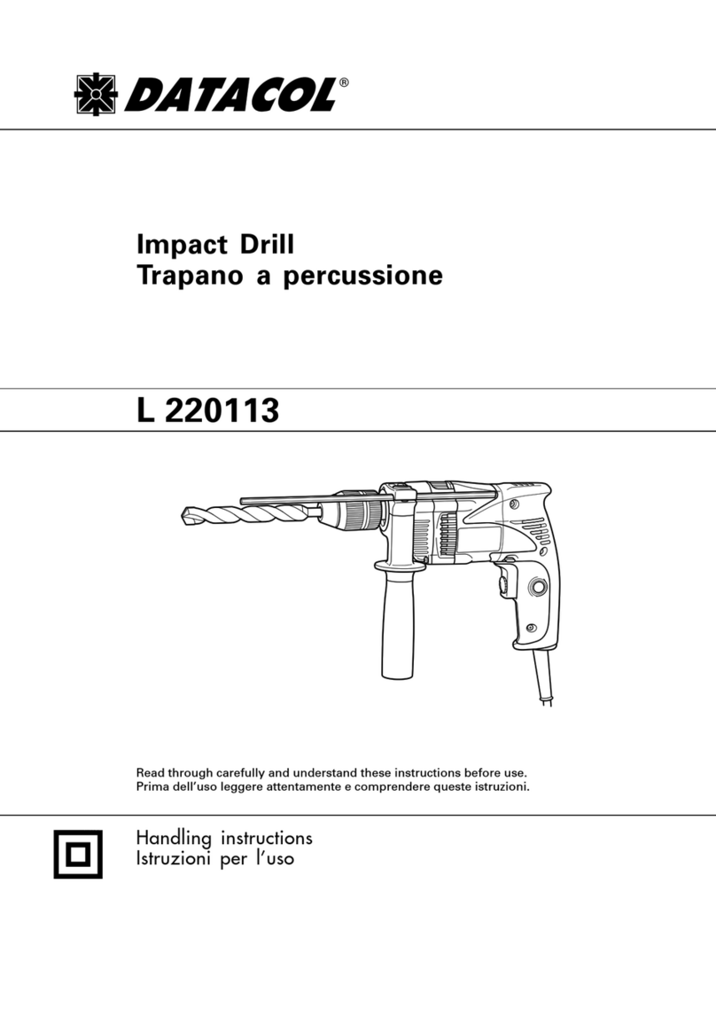
Datacol L205116 User manual

Variable speed
L205116
Cordless Driver Drill
Trapano-avvitatore a batteria
Read through carefully and understand these instructions before use.
Prima dell’uso leggere attentamente e comprendere queste instruzioni.
Handling instructions
Istruzioni per l’uso
001Cover_L205116_Eng_Ita 2/4/09, 22:161

1
4
3
2
1
6
5
78
1 2
5
2
4
3
1
6
1
7
9
8
A
B
C
D
0
0B
E
G
F
F
L
J
KI
00Table_L205116_Eng_Ita 2/4/09, 22:161

2
Q
1
2
3
4
5
(A)
(B)
910
11 12
13
15
14
16
MN
O
O
P
P
R
S P P
00Table_L205116_Eng_Ita 2/4/09, 22:162

3
English Italiano
12 V Rechargeable battery
Latch
Pull out
Insert
Handle
Push
Insert
Pilot lamp
Hole for connecting the rechargeable battery
Drill mark
Clutch dial
Triangle mark
Weak
Strong
Line
Shift knob
Low speed
High speed
Ring
Sleeve
Tighten
Loosen
Trigger switch
Selector button
R
and Lmarks
Hook
Loosen
Spring
Larger diameter faces away
1
2
3
4
5
6
7
8
9
0
A
B
C
D
E
F
G
H
I
J
K
L
M
N
O
P
Q
R
S
Batteria ricaricabile da 12 V
Fermo
Estrarre
Inserire
Impugnatura
Spingere
Inserire
Spia
Foro di collegamento della batteria ricaricabile
Simbolo di foratura
Ghiera frizione
Simbolo del triangolo
Debol
Forte
Linea
Manopola di comando
Bassa velocità
Alta velocità
Anello
Collare
Stringere
Allentare
Interruttore
Selettore
Segno
R
,
L
Gancio
Allentare
Molla
Diametro più grande lontano da sé
00Table_L205116_Eng_Ita 2/4/09, 22:163

4
Symbols
WARNING
The following show
symbols used for the
machine. Be sure that
you understand their
meaning before use.
Simboli
AVVERTENZA
Di seguito mostriamo i
simboli usati per la
macchina. Assicurarsi di
comprenderne il
significato prima dell’uso.
Read all safety
warnings and all
instructions.
Failure to follow the
warnings and
instructions may result
in electric shock, fire
and/or serious injury.
Leggere tutti gli
avvertimenti di
sicurezza e tutte le
istruzioni.
La mancata osservanza
degli avvertimenti e delle
istruzioni potrebbe essere
causa di scosse elettriche,
incendi e/o gravi lesioni.
Only for EU countries
Do not dispose of electric tools
together with household waste
material!
In observance of European
Directive 2002/96/EC on waste
electrical and electronic
equipment and its
implementation in accordance
with national law, electric tools
that have reached the end of
their life must be collected
separately and returned to an
environmentally compatible
recycling facility.
Solo per Paesi UE
Non gettare le
apparecchiature elettriche tra i
rifiuti domestici.
Secondo la Direttiva Europea
2002/96/CE sui rifiuti di
apparecchiature elettriche ed
elettroniche e la sua
attuazione in conformità alle
norme nazionali, le
apparecchiature elettriche
esauste devono essere
raccolte separatamente, al fine
di essere reimpiegate in modo
eco-compatibile.
00Table_L205116_Eng_Ita 2/4/09, 22:164

English
5
GENERAL POWER TOOL SAFETY WARNINGS
WARNING
Read all safety warnings and all instructions.
Failure to follow the warnings and instructions may result
in electric shock, fire and/or serious injury.
Save all warnings and instructions for future reference.
The term “power tool” in the warnings refers to your
mains-operated (corded) power tool or battery-operated
(cordless) power tool.
1) Work area safety
a) Keep work area clean and well lit.
Cluttered or dark areas invite accidents.
b) Do not operate power tools in explosive
atmospheres, such as in the presence of
flammable liquids, gases or dust.
Power tools create sparks which may ignite the
dust or fumes.
c) Keep children and bystanders away while
operating a power tool.
Distractions can cause you to lose control.
2) Electrical safety
a) Power tool plugs must match the outlet.
Never modify the plug in any way.
Do not use any adapter plugs with earthed
(grounded) power tools.
Unmodified plugs and matching outlets will
reduce risk of electric shock.
b) Avoid body contact with earthed or grounded
surfaces, such as pipes, radiators, ranges and
refrigerators.
There is an increased risk of electric shock if
your body is earthed or grounded.
c) Do not expose power tools to rain or wet
conditions.
Water entering a power tool will increase the
risk of electric shock.
d) Do not abuse the cord. Never use the cord for
carrying, pulling or unplugging the power tool.
Keep cord away from heat, oil, sharp edges or
moving parts.
Damaged or entangled cords increase the risk
of electric shock.
e) When operating a power tool outdoors, use an
extension cord suitable for outdoor use.
Use of a cord suitable for outdoor use reduces
the risk of electric shock.
f) If operating a power tool in a damp location
is unavoidable, use a residual current device
(RCD) protected supply.
Use of an RCD reduces the risk of electric shock.
3) Personal safety
a) Stay alert, watch what you are doing and use
common sense when operating a power tool.
Do not use a power tool while you are tired or
under the influence of drugs, alcohol or medication.
A moment of inattention while operating power
tools may result in serious personal injury.
b) Use personal protective equipment. Always wear
eye protection.
Protective equipment such as dust mask, non-
skid safety shoes, hard hat, or hearing protection
used for appropriate conditions will reduce
personal injuries.
c) Prevent unintentional starting. Ensure the switch
is in the off-position before connecting to power
source and/or battery pack, picking up or
carrying the tool.
Carrying power tools with your finger on the
switch or energising power tools that have the
switch on invites accidents.
d) Remove any adjusting key or wrench before
turning the power tool on.
A wrench or a key left attached to a rotating part
of the power tool may result in personal injury.
e) Do not overreach. Keep proper footing and
balance at all times.
This enables better control of the power tool in
unexpected situations.
f) Dress properly. Do not wear loose clothing or
jewellery. Keep your hair, clothing and gloves
away from moving parts.
Loose clothes, jewellery or long hair can be
caught in moving parts.
g) If devices are provided for the connection of
dust extraction and collection facilities, ensure
these are connected and properly used.
Use of dust collection can reduce dust related hazards.
4) Power tool use and care
a) Do not force the power tool. Use the correct
power tool for your application.
The correct power tool will do the job better and
safer at the rate for which it was designed.
b) Do not use the power tool if the switch does
not turn it on and off.
Any power tool that cannot be controlled with
the switch is dangerous and must be repaired.
c) Disconnect the plug from the power source
and/or the battery pack from the power tool
before making any adjustments, changing
accessories, or storing power tools.
Such preventive safety measures reduce the risk
of starting the power tool accidentally.
d) Store idle power tools out of the reach of children
and do not allow persons unfamiliar with the
power tool or these instructions to operate the
power tool.
Power tools are dangerous in the hands of
untrained users.
e) Maintain power tools. Check for misalignment
or binding of moving parts, breakage of parts
and any other condition that may affect the
power tools operation.
If damaged, have the power tool repaired before
use.
Many accidents are caused by poorly maintained
power tools.
f) Keep cutting tools sharp and clean.
Properly maintained cutting tools with sharp
cutting edges are less likely to bind and are
easier to control.
g) Use the power tool, accessories and tool bits
etc. in accordance with these instructions, taking
into account the working conditions and the
work to be performed.
Use of the power tool for operations different from
those intended could result in a hazardous situation.
01Eng_L205116_Eng_Ita 2/4/09, 22:175

English
6
5) Battery tool use and care
a) Recharge only with the charger specified by the
manufacturer.
A charger that is suitable for one type of battery
pack may create a risk of fire when used with
another battery pack.
b) Use power tools only with specifically designated
battery packs.
Use of any other battery packs may create a risk
of injury and fire.
c) When battery pack is not in use, keep it away from
other metal objects like paper clips, coins, keys,
nails, screws, or other small metal objects that can
make a connection from one terminal to another.
Shorting the battery terminals together may
cause burns or a fire.
d) Under abusive conditions, liquid may be ejected
from the battery; avoid contact. If contact
accidentally occurs, flush with water. If liquid
contacts eyes, additionally seek medical help.
Liquid ejected from the battery may cause
irritation or burns.
6) Service
a) Have your power tool serviced by a qualified repair
person using only identical replacement parts.
This will ensure that the safety of the power tool
is maintained.
PRECAUTION
Keep children and infirm persons away.
When not in use, tools should be stored out of reach of
children and infirm persons.
PRECAUTIONS FOR CORDLESS DRIVER
DRILL
1. Always charge the battery at a temperature of 10
– 40°C. A temperature of less than 10°C will result
in over charging which is dangerous. The battery
cannot be charged at a temperature higher than
40°C.
The most suitable temperature for charging is that
of 20 – 25°C.
2. When one charging is completed, leave the charger
for about 15 minutes before the next charging of
battery.
Do not charge more than two batteries
consecutively.
3. Do not allow foreign matter to enter the hole for
connecting the rechargeable battery.
4. Never disassemble the rechargeable battery and
charger.
5. Never short-circuit the rechargeable battery. Short-
circuiting the battery will cause a great electric
current and overheat. It results in burn or damage
to the battery.
6. Do not dispose of the battery in fire.
If the battery is burnt, it may explode.
7. When drilling in wall, floor or ceiling, check for
buried electric power cord, etc.
8. Bring the battery to the shop from which it was
purchased as soon as the post-charging battery
life becomes too short for practical use. Do not
dispose of the exhausted battery.
9. Using an exhausted battery will damage the
charger.
10. Do not insert object into the air ventilation slots
of the charger.
Inserting metal objects or inflammables into the
charger air ventilation slots will result in electrical
shock hazard or damaged charger.
11. When mounting a bit into the keyless chuck, tighten
the sleeve adequately. If the sleeve is not tight,
the bit may slip or fall out, causing injury.
SPECIFICATIONS
POWER TOOL
Model L205116
No-load speed (Low/High) 0 – 350 / 0 – 1050 min–1
Wood
Drilling
(Thickness 18mm)
25 mm
Metal Steel: 12 mm,
(Thickness 1.6mm)
Aluminum: 15 mm
Machine screw 6 mm
Driving Wood screw
5.8 mm (diameter) ×63 mm (length)
(Requires a pilot hole)
Rechargeable battery
EB1214S: Ni-Cd 12 V (1.4 Ah 10 cells)
Weight 1.5 kg
Capacity
01Eng_L205116_Eng_Ita 2/4/09, 22:176

English
7
STANDARD ACCESSORIES
Standard accessories are subject to change without
notice.
OPTIONAL ACCESSORIES (sold separately)
1. Battery (EB1214S)
Optional accessories are subject to change without
notice.
APPLICATIONS
䡬Driving and removing of machine screws, wood
screws, tapping screws, etc.
䡬Drilling of various metals.
䡬Drilling of various woods.
BATTERY REMOVAL/INSTALLATION
1. Battery removal
Hold the handle tightly and push the battery latch
to remove the battery (see Figs. 1 and 2).
CAUTION
Never short-circuit the battery.
2. Battery installation
Insert the battery while observing its polarities (see
Fig. 2).
CHARGING
Before using the driver drill, charge the battery as
follows.
1. Connect the charger power cord to the receptacle
Connecting the power cord will turn on the charger.
2. Insert the battery into the charger
Insert the battery firmly while observing its direction,
until it contacts the bottom of the charger (the pilot
lamp lights up) (See Fig. 3).
CAUTION
If the pilot lamp does not light up, pull out the
power cord from the receptacle and check the
battery mounting condition.
(1) Regarding the temperatures of the rechargeable
battery
The temperatures for rechargeable batteries are as
shown in Table 1.
Table 1 Recharging ranges of batteries
(2) Regarding recharging time
Depending on the combination of the charger and
batteries, the charging time will become as shown
in Table 2.
Table 2 Charging time (At 20°C)
The pilot lamp goes off to indicate that the battery
is fully charged.
The battery charging time becomes longer when a
temperature is low or the voltage of the power
source is too low.
When the pilot lamp does not go off even if more
than 120 minutes have elapsed after starting of the
charging, stop the charging and contact your
AUTHORIZED SERVICE CENTER.
CAUTION
If the battery is heated due to direct sunlight,
etc., just after operation, the charger pilot lamp
may not light up. At that time, cool the battery
first, then start charging.
3. Disconnect the charger’s power cord from the
receptacle
4. Hold the charger firmly and pull out the battery
NOTE
After charging, pull out batteries from the charger
first, and then keep the batteries properly.
Regarding electric discharge in case of new batteries,
etc.
As the internal chemical substance of new batteries
and batteries that have not been used for an
extended period is not activated, the electric
discharge might be low when using them the first
and second time. This is a temporary phenomenon,
and normal time required for recharging will be
restored by recharging the batteries 2 – 3 times.
How to make the batteries perform longer.
(1) Recharge the batteries before they become
completely exhausted.
When you feel that the power of the tool becomes
weaker, stop using the tool and recharge its battery.
If you continue to use the tool and exhaust the
electric current, the battery may be damaged and
its life will become shorter.
CHARGER
Model UC18YG
Charging voltage 7.2
–
18V
Weight 0.3 kg
1Plus driver bit (No. 2 ×65L) ...... 1
L205116 2Charger (UC18YG) .......................... 1
3Plastic case ....................................... 1
Charger UC18YG
Battery
EB1214S
Approx. 30 min.
Temperatures at
Rechargeable batteries which the battery
can be recharged
EB1214S 0°C – 45°C
01Eng_L205116_Eng_Ita 2/4/09, 22:177

English
8
(2) Tightening torque indication
The tightening torque differs depending on the type
of screw and the material being tightened.
The unit indicates the tightening torque with the
numbers “1, 3, 5 ... 22” on the clutch dial, and a
dots. The tightening toque at position “1” is the
weakest and the torque is strongest at the highest
number (See Fig. 4).
(3) Adjusting the tightening torque
Rotate the clutch dial and line up the numbers “1,
3, 5 ... 22” on the clutch dial, or the dots, with the
triangle mark on the outer body. Adjust the clutch
dial in the weak or the strong torque direction
according to the torque you need.
CAUTION
䡬The motor rotation may be locked to cease while
the unit is used as drill. While operating the driver
drill, take care not to lock the motor.
䡬Too long hammering may cause the screw broken
due to excessive tightening.
3. Change rotation speed
Operate the shift knob to change the rotational
speed. Move the shift knob in the direction of the
arrow (See Figs. 6 and 7).
When the shift knob is set to “LOW”, the drill
rotates at a low speed. When set to “HIGH”, the
drill rotates at a high speed.
CAUTION
䡬When changing the rotational speed with the shift
knob, confirm that the switch is off.
Changing the speed while the motor is rotating will
damage the gears.
䡬When setting the shift knob to “HIGH” (high speed)
and the position of the clutch dial is “17” or “22”,
it may happen that the clutch does not engaged
and that the motor is locked. In such a case, please
set the shift knob to “LOW” (low speed).
䡬If the motor is locked, immediately turn the power
off. If the motor is locked for a while, the motor
or battery may be burnt.
4. The scope and suggestions for uses
The usable scope for various types of work based
on the mechanical structure of this unit is shown
in Table 3.
(2) Avoid recharging at high temperatures.
A rechargeable battery will be hot immediately after
use. If such a battery is recharged immediately after
use, its internal chemical substance will deteriorate,
and the battery life will be shortened. Leave the
battery and recharge it after it has cooled for a
while.
PRIOR TO OPERATION
1. Setting up and checking the work environment
Check if the work environment is suitable by
following the precautions.
HOW TO USE
1. Confirm the clutch dial position (See Fig. 4)
The tightening torque of this unit can be adjusted
according to the clutch dial position, at which the
clutch dial is set.
(1) When using this unit as a screwdriver, line up the
one of the numbers “1, 3, 5 ... 22” on the clutch
dial, or the dots, with the triangle mark on the outer
body.
(2) When using this unit as a drill, align the clutch dial
drill mark “ ” with the triangle mark on the outer
body.
CAUTION
䡬The clutch dial cannot be set between the numerals
“1, 3, 5 ... 22” or the dots.
䡬Do not use with the clutch dial numeral between
“22” and the line at the middle of the drill mark.
Doing so may cause damage (See Fig. 5).
2. Tightening torque adjustment
(1) Tightening torque
Tightening torque should correspond in its intensity
to the screw diameter. When too strong torque is
used, the screw head may be broken or be injured.
Be sure to adjust the clutch dial position according
to the screw diameter.
Work Suggestions
Wood
Drilling Steel Use for drilling purpose.
Aluminum
Machine screw Use the bit or socket matching the screw diameter.
Driving Wood screw Use after drilling a pilot hole.
Table 3
01Eng_L205116_Eng_Ita 2/4/09, 22:178

English
9
5. How to select tightening torque and rotational speed
Table 4
CAUTION
䡬The selection examples shown in Table 4 should
be considered as general standard. As different
types of tightening screws and different materials
to be tightened are used in actual works proper
adjustments are naturally necessary.
䡬When using the driver drill with a machine screw
at HIGH (high speed), a screw may damage or a
bit may loose due to the tightning torque is too
strong. Use the driver drill at LOW (low speed)
when using a machine screw.
6. Mounting and dismounting of the bit
(1) After inserting a driver bit, etc. into the keyless drill
chuck, firmly grasp the ring and tighten the sleeve
by turning it toward the right (in the clockwise
direction as viewed from the front) (See Fig. 8).
䡬If the sleeve becomes loose during operation, tighten
it further. The tightening force becomes stronger
when the sleeve is tightened additionally.
(2) Dismounting the bit
Firmly grasp the ring and loosen the sleeve by
turning it toward the left (in the counter-clockwise
direction as viewed from the front) (See Fig. 8).
CAUTION
䡬When it is no longer possible to loosen the sleeve,
use a vise or similar instrument to secure the bit.
Set the clutch mode between 1 and 11, and then
turn the sleeve to the loose side (left side) while
operating the clutch. It should be easy now to
loosen the sleeve.
7. Confirm that the battery is mounted correctly
8. Check the rotational direction
The bit rotates clockwise (viewed from the rear
side) by pushing the R-side of the selector button.
The L-side of the selector button is pushed to turn
the bit counterclockwise (See Fig. 9) (The Land
R
marks are provided on the body).
9. Switch operation
䡬When the trigger switch is depressed, the tool
rotates. When the trigger is released, the tool stops.
䡬The rotational speed of the drill can be controlled
by varying the amount that the trigger switch is
pulled. Speed is low when the trigger switch is
pulled slightly and increases as the trigger switch
is pulled more.
NOTE
䡬A buzzing noise is produced when the motor is
about to rotate; This is only a noise, not a machine
failure.
10. Using the hook
CAUTION
䡬When using the hook, pay sufficient attention so
that the main equipment does not fall. If the tool
falls, there is a risk of accident.
䡬Do not attach the tip tool except phillips bit to the
tool main unit when carrying the tool main unit with
the hook suspended from a waist belt.
Injury may result if you carry the equipment
suspended from the waist belt with sharp tipped
components such as drill bit attached.
The hook can be installed on the right or left side and
the angle can be adjusted in 5 steps between 0° and
80°.
(1) Operating the hook
(a) Pull out the hook toward you in the direction
of arrow (A) and turn in the direction of arrow
(B) (Fig. 10).
(b) The angle can be adjusted in 5 steps (0°, 20°,
40°, 60°, 80°).
Adjust the angle of the hook to the desired
position for use.
(2) Switching the hook position
CAUTION
Incomplete installation of the hook may result in
bodily injury when used.
(a) Securely hold the main unit and remove the
screw using a slotted head screwdriver or a coin
(Fig. 11).
(b) Remove the hook and spring (Fig. 12).
(c) Install the hook and spring on the other side and
securely fasten with screw (Fig. 13).
NOTE
Pay attention to the spring orientation. Install the
spring with larger diameter away from you (Fig. 13).
(3) Using the bit holder (Hook with bit holder)
䡬Installing the bit
Slide the bit from the side and then insert firmly
until the groove on the bit locks in the protruded
section of the hook.
䡬Removing the bit
Securely hold the main unit and pull out the bit
by holding the tip with your thumb (Fig. 14).
CAUTION
䡬Only STANDARD ACCESSORIES phillips bit (No. 2
×65L; Code No. 983006) may be used. Do not use
other bits since they may come loose.
Use Clutch Dial Rotating speed selection (Position of the shift knob)
Position LOW (Low speed) HIGH (High speed)
Machine screw 1 – 22 For 4 mm or smaller diameter
screws.
Driving
Wood screw 1 –
For 5.8 mm or smaller nominal
diameter screws.
Wood F
or 25 mm or smaller
diameters
.
Drilling
Metal
For drilling with a metal
working drill bit.
For 6 mm or smaller
diameter screws.
For 3.8 mm or smaller
nominal diameter screws.
For 12 mm or smaller
diameters.
01Eng_L205116_Eng_Ita 2/4/09, 22:179

English
10
11. Using the bit holder
CAUTION
䡬Stow the bit in the specified location on the tool.
If the tool is used with the bit stowed improperly,
the bit may fall and cause bodily injury.
䡬Do not stow bits that are of a different length,
gauge or dimension than the plus driver bit (65 mm
long) included in the STANDARD ACCESSORIES.
The bit may fall and cause bodily injury.
(1) Removing the bit
Securely hold the main unit and pull out the bit
by holding the tip with your thumb (Fig. 15).
(2) Installing the Bit
Install the bit with steps opposite of when removing.
Insert the bit so that the right and left sides are
equal, as shown in Fig. 16.
MAINTENANCE AND INSPECTION
1. Inspecting the tool
Since use of as dull tool will degrade efficiency and
cause possible motor malfunction, sharpen or
replace the tool as soon as abrasion is noted.
2. Inspecting the mounting screws
Regularly inspect all mounting screws and ensure
that they are properly tightened. Should any of the
screws be loose, retighten them immediately. Failure
to do so could result in serious hazard.
3. Cleaning on the outside
When the driver drill is stained, wipe with a soft
dry cloth or a cloth moistened with soapy water.
Do not use chloric solvents, gasoline or paint thinner,
for they melt plastics.
4. Storage
Store the driver drill in a place in which the tempera
ture is less than 40°C and out of reach of children.
5. Service parts list
CAUTION
Repair, modification and inspection of Power Tools
must be carried out by an Authorized Service Center.
This Parts List will be helpful if presented with the
tool to the Authorized Service Center when
requesting repair or other maintenance.
In the operation and maintenance of power tools,
the safety regulations and standards prescribed in
each country must be observed.
MODIFICATIONS
Power Tools are constantly being improved and
modified to incorporate the latest technological
advancements.
Accordingly, some parts may be changed without
prior notice.
GUARANTEE
We guarantee DATACOL Power Tools in accordance
with statutory/country specific regulation. This guarantee
does not cover defects or damage due to misuse,
abuse, or normal wear and tear. In case of complaint,
please send the Power Tool, undismantled, with the
GUARANTEE CERTIFICATE found at the end of this
Handling instruction, to an Authorized Service Center.
NOTE
Due to DATACOL’s continuing program of research and
development, the specifications herein are subject to
change without prior notice.
Information concerning airborne noise and vibration
The measured values were determined according to
EN60745 and declared in accordance with ISO 4871.
Measured A-weighted sound power level: 74 dB (A)
Measured A-weighted sound pressure level: 63 dB (A)
Uncertainty KpA: 3 dB (A).
Wear hearing protection.
Vibration total values (triax vector sum) determined
according to EN60745.
As drill:
Vibration emission value ah, D
=
1.5 m/s
2
Uncertainty K = 1.5 m/s2
WARNING
䡬The vibration emission value during actual use of
the power tool can differ from the declared value
depending on the ways in which the tool is used.
䡬To identify the safety measures to protect the
operator that are based on an estimation of exposure
in the actual conditions of use (taking account of
all parts of the operating cycle such as the times
when the tool is switched off and when it is running
idle in addition to the trigger time).
01Eng_L205116_Eng_Ita 2/4/09, 22:1710

Italiano
11
AVVERTIMENTI GENERALI DI SICUREZZA
SUGLI UTENSILI ELETTRICI
AVVERTENZA
Leggere tutti gli avvertimenti di sicurezza e tutte le
istruzioni.
Lamancataosservanzadegliavvertimentiedelleistruzioni
potrebbe essere causa di scosse elettriche, incendi e/o
gravi lesioni.
Salvare tutti gli avvertimenti e le istruzioni per riferimenti
futuri.
Il termine “elettroutensili” riportato nelle avvertenze si
riferisce agli elettroutensili azionati con alimentazione di
rete (via cavi) o a batterie (senza cavi).
1) Sicurezza dell’area operativa
a) Mantenere l'area operativa pulita e ordinata.
Aree operative sporche o disordinate possono
favorire gli infortuni.
b) Non utilizzare gli elettroutensili in atmosfere
esplosive, ad es. in presenza di liquidi, gas o
polveri infiammabili.
Gli elettroutensili generano delle scintille che
potrebbero accendere la polvere o i fumi.
c) Tenere lontani bambini e astanti durante l'utilizzo
degli elettroutensili.
Qualsiasi distrazione può essere causa di perdita
di controllo.
2) Sicurezza elettrica
a) Le spine degli elettroutensili devono essere idonee
alle prese disponibili.
Non modificare mai le prese.
Con gli elettroutensili a massa (messi a terra),
non utilizzare alcun adattatore.
L'utilizzo di spine intatte e corrispondenti alle prese
disponibili ridurrà il rischio di scosse elettriche.
b) Evitare qualsiasi contatto con le superfici a massa
o a terra, quali tubi, radiatori, fornelli e frigoriferi.
In caso di messa a terra o massa del corpo, sussiste
un maggior rischio di scosse elettriche.
c) Non esporre gli elettroutensili alla pioggia o
all'umidità.
La penetrazione di acqua negli elettroutensili
aumenterà il rischio di scosse elettriche.
d) Non tirare il cavo. Non utilizzarlo per il trasporto,
o per tirare o scollegare l'elettroutensile.
Tenere il cavo lontano da fonti di calore, oli, bordi
appuntiti o parti in movimento.
Cavi danneggiati o attorcigliati possono
aumentare il rischio di scosse elettriche.
e) Durante l'uso degli elettroutensili all'esterno,
utilizzare una prolunga idonea per usi esterni.
L'utilizzo di cavi per esterno riduce il rischio di
scosse elettriche.
f) Se è impossibile evitare l’impiego di un utensile
elettrico in un luogo umido, utilizzare
l’alimentazione protetta da un dispositivo a
corrente residua (RCD).
L’uso di un RCD riduce il rischio di scosse elettriche.
3) Sicurezza personale
a) Durante l'uso degli elettroutensili, state all'erta,
verificate ciò che state eseguendo e adottate
sempre il buon senso.
Non utilizzate gli elettroutensili qualora siate stanchi,
sotto l'influenza di farmaci, alcol o cure mediche.
Anche un attimo di disattenzione durante l'uso
degli elettroutensili potrebbe essere causa di gravi
lesioni personali.
b) Indossate l'attrezzatura di protezione personale.
Indossate sempre le protezioni oculari.
L'attrezzatura protettiva, quali maschera facciale,
calzature antiscivolo, caschi o protezioni oculari
ridurrà il rischio di lesioni personali.
c) Impedite le accensioni involontarie. Prima del
collegamento a una sorgente di alimentazione e/
o pacco batteria e prima di raccogliere o
trasportare l’utensile, verificate che l'interruttore
sia posizionato su OFF.
Il trasporto degli elettroutensili tenendo le dita
sull'interruttore o l’attivazione elettrica degli
utensile che hanno l’interruttore su ON, implica il
rischio di incidenti.
d) Prima di attivare l'elettroutensile, rimuovete
qualsiasi chiave di regolazione.
Lasciando la chiave in un componente in rotazione
dell'elettroutensile, sussiste il rischio di lesioni
personali.
e) Mantenersi in equilibrio. Mantenersi sempre su
due piedi, in equilibrio stabile.
Ciò consente di controllare al meglio
l'elettroutensile in caso di situazioni impreviste.
f) Vestirsi in modo adeguato. Non indossare abiti
larghi o gioielli. Tenere i capelli, gli abiti e i guanti
lontano dalle parti in movimento.
Abiti allentati, gioielli e capelli lunghi potrebbero
impigliarsi nelle parti in movimento.
g) In caso di dispositivi provvisti di collegamento ad
apparecchiature di rimozione e raccolta polveri,
verificare che queste siano collegate e utilizzate
in modo adeguato.
L'utilizzo della raccolta della polvere può ridurre i
rischi connessi alle polveri.
4) Utilizzo e manutenzione degli elettroutensili
a) Non utilizzare elettroutensili non idonei. Utilizzare
l'elettroutensile idoneo alla propria applicazione.
Utilizzando l'elettroutensile corretto, si garantirà
un'esecuzione migliore e più sicura del lavoro,
alla velocità di progetto.
b) Non utilizzare l'elettroutensile qualora non sia
possibile accenderlo/spegnerlo tramite
l'interruttore.
É pericoloso utilizzare elettroutensili che non
possano essere azionati dall'interruttore.
Provvedere alla relativa riparazione.
c) Prima di effettuare qualsiasi regolazione, sostituire
gli accessori o depositare gli elettroutensili,
scollegare la spina dalla presa elettrica e/o il pacco
batteria dall’utensile elettrico.
Queste misure di sicurezza preventive riducono il
rischio di avvio involontario dell'elettroutensile.
d) Depositare gli elettroutensili non utilizzati lontano
dalla portata dei bambini ed evitare che persone
non esperte di elettroutensili o non a conoscenza
di quanto riportato sulle presenti istruzioni
azionino l'elettroutensile.
É pericoloso consentire che utenti non esperti
utilizzino gli elettroutensili.
02Ita_L205116_Eng_Ita 2/4/09, 22:1711

Italiano
12
e) Manutenzione degli elettroutensili. Verificare che
non vi siano componenti in movimento disallineati
o bloccati, componenti rotti o altre condizioni
che potrebbero influenzare negativamente il
funzionamento dell'elettroutensile.
In caso di guasti, provvedere alla riparazione
dell'elettroutensile prima di riutilizzarlo.
Molti incidenti sono causati da una scarsa
manutenzione.
f) Mantenere gli strumenti di taglio affilati e puliti.
Gli strumenti di taglio in condizioni di
manutenzione adeguata, con bordi affilati, sono
meno soggetti al bloccaggio e sono più facilmente
controllabili.
g) Utilizzare l'elettroutensile, gli accessori, le barrette,
ecc. in conformità a quanto riportato nelle presenti
istruzioni, tenendo in debita considerazione le
condizioni operative e il tipo di lavoro da eseguire.
L’uso dell’utensile elettrico per operazioni diverse
da quelle previste potrebbe causare una situazione
pericolosa.
5) Utilizzo e cura dell’utensile batteria
a) Ricaricare solo con il caricatore specificato dal
produttore.
Un caricatore adatto per un tipo di gruppo batteria
può creare un rischio di incendio quando viene
utilizzato con un altro gruppo batteria.
b) Usare utensili elettrici con gruppi batteria
specificatamente designati.
L’utilizzo di qualsiasi altro gruppo batteria può
creare un rischio di lesioni e incendi.
c) Quando il gruppo batteria non viene utilizzato,
tenerlo lontano da altri oggetti metallici come
graffette, monete, chiavi, chiodi, viti, o altri piccoli
oggetti metallici che possono creare una
connessione da un terminale a un altro.
Cortocircuitare i terminali della batteria insieme
può causare ustioni o incendi.
d) In condizioni abusive, del liquido può fuoriuscire
dalla batteria; evitare il contatto. Se il contatto
si verifica accidentalmente, sciacquare con acqua.
Se il liquido entra a contatto con gli occhi,
richiedere assistenza medica.
Il liquido che fuoriesce dalla batteria può causare
irritazioni o ustioni.
6) Assistenza
a) Affidate le riparazioni dell'elettroutensile a
persone qualificate che utilizzino solamente parti
di ricambio identiche.
Ciò garantirà il mantenimento della sicurezza
dell'elettroutensile.
PRECAUZIONI
Tenere lontano dalla portata di bambini e invalidi.
Quando non utilizzati, gli strumenti dovranno essere
deposti lontano dalla portata di bambini e invalidi.
PRECAUZION PER L’USO DEL
TRAPANOAVVITATORE A BATTERIA
1. Caricare la batteria ad una temperatura di 10 –
40°C. Una temperatura di meno di 10°C può
provocare sovraccarico, il che è pericoloso. La
batteria non può essere ricaricata ad una
temperatura superiore ai 40°C. La temperatura
ideale è compresa 20 – 25 gradi.
2. Quando un’operazione di caricatura è terminata,
prima di iniziarne una seconda, lasciare che il
caricatore riposi per 15 minuti.
Non caricare più di due batterie consecutivamente.
3. Non permettere che sostanze estranee entrino nel
foro di collegamento della batteria ricaricabile.
4. Non smontare mai la batteria ricaricabile e il
caricatore.
5. Non provocare assolutamente mai dei corto-circuiti
alla batteria ricaricabile. Il fenomeno provoca
surriscaldamento e grande corrente elettrica. Può
quindi causare bruciature o danni alla batteria.
6. Non gettare la batteria nel fuoco. Può esplodere.
7. Quando si fanno fori sulle pareti, pavimenti o soffitti,
controllare che non ci siano cavi elettrici nascosti.
8. Non appena la vita della batteria dopo le operazioni
di ricaricatura diventa troppo breve per fini pratici,
si porti la batteria al negozio dove è stata
acquistata. Non la si getti mai via.
9. Usando una batteria scarica, il caricatore può venir
danneggiato.
10. Non inserire nessun oggetto nelle fessure di
ventilazione del caricatore.
Inserendo oggetti metallici o infiammabili nelle
fessure di ventilazione, si possono causare
facilmente delle scosse electtriche, o si può
danneggiare il caricatore.
11. Per montare una punta o una trivella da trapano
nel mandrino senza chiave, stringere il manicotto
in maniera adeguata. Se il manicotto non è ben
stretto, la punta o la trivella da trapano può
scivolare o cadere, con il pericolo di lesioni alle
persone.
02Ita_L205116_Eng_Ita 2/4/09, 22:1712

Italiano
13
CARICATORE
Modello UC18YG
Votaggio di carica
7,2
–
18V
Peso 0,3 kg
ACCESSORI STANDARD
Gli accessori standard possono essere cambiati senza
preavviso.
ACCESSORI FACOLTATIVI (venduti a parte)
1. Batteria (EB1214S)
Gli accessori disponibili a richiesta possono essere
cambiati senza preavviso.
APPLICAZIONI
䡬Per stringere o togliere delle viti di macchina, delle
viti per legno, delle viti mordenti etc.
䡬Per la foratura di metalli diversi.
䡬Per la foratura di legni diversi.
1Cacciavite a croce (n.2 ×65L) ... 1
L205116 2Caricatore (UC18YG) ....................... 1
3Custodia in plastica ......................... 1
RIMOZIONE E INSTALLAZIONE DELLA
BATTERIA
1. Smontaggio della batteria
Tenere saldamente l’impugnatura e spingere il fermo
della batteria, in modo da smontaria (Ved. Fig. 1
e 2).
ATTENZIONE
Non mettere la batteria in corto circuito.
2. Montaggio della batteria
Inserire la batteria facendo attenzione alla corretta
collocazione delle polarità (Ved. Fig. 2).
RICARICA
Prima di usare il trapano avvitatore, caricare la batteria
come di seguito indicato.
1. Collegare il cavo del caricatore alla presa AC
In tal modo si accenderà il caricatore.
2. Inserire la batteria nel caricatore
Inserire saldamente la batteria facendo attenzione
al suo orientamento, fino a che viene in contatto
con il fondo del caricatore (la lampada spia non si
illumina) (Ved. Fig. 3).
ATTENZIONE
Se la lampada spia non si illumina, togliere il
cavo di corrente dalla presa di rete e controllare
come è inserita la batteria.
(1) Temperatura della batteria ricaricabile
Le temperature per le batterie ricaricabili sono quelle
indicate in Tabella 1.
Tabella 1 Gamma di temperature per la ricarica delle
batterie
CARATTERISTICHE
UTENSILE ELETTRICO
Modello L205116
Velocità a vuoto (Bassa/Alta) 0 – 350 / 0 – 1050 min–1
Legno
Perfora-
(Spessore 18mm)
25 mm
zione Metallo Acciaino: 12 mm,
(Spessore 1,6mm)
Alluminio: 15 mm
Avvita-
Vite di macchina
6 mm
mento Vite per legno
5,8 mm (diametro) ×63 mm (lunghezza)
(Questo é un foro preliminare)
Batterie rechargeable
EB1214S: Ni-Cd 12 V (1,4 Ah 10 batterie)
Peso 1,5 kg
Capacità
Temperature
Batterie ricaricabili di carica per le
batterie
EB1214S 0°C – 45°C
02Ita_L205116_Eng_Ita 2/4/09, 22:1713

Italiano
14
(2) Tempo di carica necessario
A seconda della combinazione di caricatore e
batterie, il tempo di carica è come indicato nella
Tabella 2.
Tabella 2 Tempo di carica (a 20°C)
La lampada spia si spegne quando la batteria è
caricata appieno.
Il tempo di carica della batteria diventa più lungo
a basse temperature o quando la tensione di
alimentazione è troppo bassa.
Se la lampada spia non si spegne neppure dopo
che sono trascorse più 120 minuti dall'inizio della
carica, interrompere la carica e rivolgersi ad un
CENTRO DI ASSISTERZA AUTORIZZATO.
ATTENZIONE
Se la batteria è calda a causa dei raggi diretti
del sole ad operazione eseguita, la lampada spia
del caricatore a volte non si illumina. Prima di
iniziare le operazioni di carico raffreddare la
batteria.
3. Scollegare il cavo di alimentazione del caricatore
dalla presa CA
4. Tenere saldamente il caricatore e estrarre la batteria
NOTA
Dopo aver terminato la carica, estrarre le batterie
dal caricabatterie e quindi conservare le batterie in
maniera adeguata.
Scarica nel caso di batterie nuove, ecc.
Poiché la sostanza chimica interna delle batterie
nuove e delle batterie che non sono state usate per
un lungo periodo di tempo non è attivata, la scarica
esterna può essere abbassata quando le si usa per
la prima e seconda volta. Questo è un fenomeno
temporaneo e il tempo normale necessario per la
carica viene ripristinato ricaricando la batteria per
2 o 3 volte.
Come mantenere più lunga la durata delle batterie.
(1) Ricaricare le batterie prima che si scarichino
completamente.
Quando si sente che la potenza dell’attrezzo si
indebolisce, interrompere l’uso e ricaricare la
batteria. Se si continua l’uso e si finisce la corrente
elettrica, la batteria può essere danneggiata e la sua
durata abbreviarsi.
(2) Evitare di raggiungere alte temperature.
Una batteria ricaricabile si riscalda subito dopo
l’uso. Se si ricarica una batteria subito dopo averla
usata, la sostanza chimica interna viene deteriorata
e la durata della batteria abbreviata. Consentire alla
batteria di raffreddarsi per un po’e quindi ricaricarla.
PRIMA DI INIZIARE LE OPERAZIONI
1. Stabilire e controllare l’ambiente di lavoro
Controllare che l’ambiente di lavoro sia adatto
seguendo le necessarie precauzioni.
Caricatore UC18YG
Batteria
EB1214S Cira. 30 min
OPERAZIONE
1. Verificare la posizione della ghiera della frizione
(Ved. Fig. 4)
La coppia di serraggio dell'utensile può essere
impostata spostando la ghiera della frizione nella
posizione appropriata.
(1) Per utilizzare l’utensile come avvitatore, allineare
uno dei numeri “1, 3, 5 ... 22” o uno dei punti sulla
ghiera della frizione con il triangolo presente sul
corpo dell’utensile.
(2) Per utilizzare l'utensile come trapano, allineare il
simbolo del trapano “ ” sulla ghiera con il triangolo
presente sul corpo dell'utensile.
ATTENZIONE
䡬Per evitare possibili danni all’utensile
La ghiera della frizione non deve essere mai collocata
su posizioni intermedie tra i numeri “1, 3, 5 ... 22”
o fra i punti.
䡬Non utilizzare l’utensile con la ghiera della frizione
situata in posizione intermedia tra il numero “22”
e la linea al centro del simbolo del trapano. Questo
può causare danni (Vedere la Fig. 5).
2. Regolazione della coppia di serraggio
(1) Coppia di serraggio
La coppia di serraggio deve essere regolata in
corrispondenza del diametro della vite. Se la forza
di serraggio è troppo elevata, la vite si può rompere
o la testa ne può risultare danneggiata. Assicurarsi
di posizionare la ghiera della frizione nella posizione
appropriata per il diametro delle viti utilizzate.
(2) Indicazione della coppia di serraggio
La coppia di serraggio necessaria varia a seconda
del tipo di vite e del materiale su cui si lavora.
L’utensile indica la coppia di serraggio impostata
mediante una scala numerata “1, 3, 5 ... 22” e punti
sulla ghiera della frizione. Con la ghiera in posizione
1, verrà applicata la coppia di serraggio minore.
Con la ghiera in posizione 22 verrà applicata la
coppia di serraggio massima (Vedere la Fig. 4).
(3) Regolazione della coppia di serraggio
Ruotare la ghiera della frizione per allineare il numero
desiderato della scala “1, 3, 5 ... 22” o i punti con
il triangolo di riferimento sul corpo dell’utensile.
Selezionare la coppia di serraggio necessaria
ruotando la ghiera fra i valori minimo e massimo.
ATTENZIONE
䡬La rotazione del motore può essere bloccata, quando
si usa l’utensile come trapano.
Usando il trapano avvitatore, fare attenzione a non
bloccare il motore.
䡬Facendo lavorare a percussione l’utensile durante
un tempo troppo prolungato, è possibile che la vite
si rompa.
3. Cambio della velocità di rotazione
Usare la manopola d’intercambio per cambiare la
velocità di rotazione. Premere il pulsante di blocco
per liberare e spostare la manopola d’intercambio
in direzione della freccia (Ved. Figs. 6 e 7).
Quando la manopola d’intercambio è portata su
“LOW” il trapano rota a bassa velocità. Su “HIGH”
il trapano rota ad alta velocità.
02Ita_L205116_Eng_Ita 2/4/09, 22:1714

Italiano
15
ATTENZIONE
䡬Quando si cambia la velocità di rotazione con la
manopola del cambio, verificare che l'interruttore
sia disattivato.
Se si cambia la velocità con il motore in moto si
causeranno danni agli ingranaggi.
䡬Se si cerca di posizionare il selettore velocità su
“HIGH” (alta velocità) con la ghiera frizione sulle
posizioni fra “17” e “22”, può accadere che la
frizione non si innesti e il motore si blocchi. In
questo caso spostare il selettore velocità su “LOW”
(bassa velocità).
䡬Se il motore si blocca, togliere immediatamente la
corrente.
Se il motore si blocca per qualche attimo, il motore
o la batteria possono essere bruciati.
4. Suggerimenti e limite d’uso
La gamma di utilizzo per vari tipi di lavoro in base
alla struttura meccanica dell'utensile è indicata nella
Tabella 3.
Tabella 3
Lavoro Suggerimenti
Legno
Forature Acciaio Uso dell'utensile per forare
Alluminio
Serraggio di Viti per macchine Usare punta o chiave adatte per il diametro della vite
viti Viti per legno Usare solo dopo ave eseguito un foro di preparazione
5. Scelta della coppia di serraggio e della frequenza di rotazione
Tabella 4
Uso
Posizione della
Selezione della velocità di rotazione (Posizione della manopola di selezione)
ghiera della frizione
LOW (bassa velocità) HIGH (alta velocità)
Serraggio
Viti di macchina 1 – 22 Per viti de 4 mm diametro o
meno.
di viti
Viti per legno 1 – Per viti di 5,8 mm diametro
nominale o meno.
Legno Per diametri di 25 mm
o
meno.
Foratura
Metallo Per foratura con punta per il
ferro.
Per viti di 6 mm diametro o
meno.
Per viti di 3,8 mm diametro
nominale o meno.
For 12 mm or smaller
diameters.
ATTENZIONE
䡬Gli esempi di cui alla Tabella 4 sono da considerarsi
come indicativi. I diversi tipi di viti e di materiale
usati in pratica rendono necessari degli
aggiustamenti dei valori dati.
䡬Quando si usa una punta con una vite di macchina
ad alta velocità (HIGH), si può danneggiare una vite
o si può allentare la punta a causa del fissaggio
troppo forte. Usare la punta a bassa velocità (LOW)
quando si impiega una vite di macchina.
6. Montaggio e smontaggio della punta
(1) Dopo aver inserito una punta di trapano, ecc. nel
mandrino autoserrante, afferrare saldamente l’anelle
e stringere il collare girandolo verso destra (in senso
orario quando visto da davanti) (Vedere Fig. 8).
䡬Se il collare dovesse allentarsi durante il
funzionamento, stringerlo ulteriormente. La forza
serrante aumenta quando il collare viene stretto.
(2) Per staccare l’attrezzo dalla punta
Afferrare saldamente l’anello e allentare il collare
girandolo verso sinistra (in senso antiorario quando
visto da davanti) (Ved. Fig. 8).
ATTENZIONE
䡬Quando non è possibile svitare il collare, stringere
l’attrezzo inserito in una morsa, ecc., regolare il
modo frizione su 1–11 e girare il collare in senso
antiorario usando la frizione. A questo punto è
facile girare il collare.
7. Assicurarsi che la batteria sia montata in modo
corretto
8. Controllare la direzione della rotazione
La punta gira in senso orario (come visto dal retro)
se si preme la parte di destra R del selettore.
Per far girare la punta in senso antiorario premere
la parte sinistra L del selettore (Vedere Fig. 9)
(I contrassegni
L
ed
R
sono apportati sul corpo
dell’attrezzo).
9. Funzionamento dell'interruttore
䡬Premendo il grilletto interruttore, l’utensile si mette
in movimento.
Lasciando andare il grilletto, il motore si ferma.
䡬La velocit† di rotazione del trapano può essere
dell’interruttore viene premuto. La velocità è bassa
quando il grilletto dell’interruttore viene premuto
leggermente, e aumenta a mano a mano che
l’interrutoore viene premuto maggiormente.
02Ita_L205116_Eng_Ita 2/4/09, 22:1715

Italiano
16
NOTA
䡬Prima di cominciare a ruotare, il motore produce
un ronzio. Tale rumore non è indice di cattivo
funzionamento delle macchina.
10. Uso del gancio
ATTENZIONE
䡬Quando si usa un gancio, fare attenzione a che
l’apparecchiatura principale non cada. Se l’utensile
dovesse cadere, si potrebbero verificare incidenti.
䡬Non attaccare alcuna punta utensile tranne una
punta con testa a croce all’unità principale
dell’utensile quando si trasporta l’unità principale
utensile con il gancio agganciato alla cintura.
Si può rimanere feriti se si trasporta l’apparecchiatura
attaccata alla cintura con componenti dalla punta
aguzza, come una punta trapano.
Il gancio può essere installato sul lato destro o sinistro
e l’angolazione può essere regolata in 5 scatti tra 0°
e 80°.
(1) Uso del gancio
(a) Estrarre il gancio verso di sé in direzione della
freccia (A) e girarlo in direzione della freccia (B)
(Fig. 10).
(b) L’angolazione può essere regolata in 5 scatti (0°,
20°, 40°, 60°, 80°). Regolare l’angolazione del
gancio sulla posizione desiderata per l’uso.
(2) Cambiamento della posizione del gancio
ATTENZIONE
Un’installazione incompleta del gancio può causare
ferite durante l’uso.
(a) Trattenere saldamente l’unità principale e
rimuovere la vite con un cacciavite a lama piatta
o una moneta (Fig. 11).
(b) Rimuovere il gancio e la molla (Fig. 12).
(c) Installare il gancio e la molla sull’altro lato e
fissare saldamente con la vite (Fig. 13).
NOTA
Fare attenzione all’orientamento della molla.
Installare la molla con il diametro più grande lontano
da sè (Fig. 13).
(3) Uso del portatesta (gancio con portapunta)
䡬Installazione della testa
Far scivolare la punta da lato e quindi inserire
saldamente finché la scanalatura sulla punta si
innesta nella sezione sporgente del gancio.
䡬Rimozione della testa
Trattenere saldamente l’unità principale e tirare
fuori la testa trattenendone l’estremità con il
pollice (Fig. 14).
ATTENZIONE
䡬Può essere usata solo la punta philips degli
ACCESSORI STANDARD (N. 2 ×65L; codice n.
983006). Non usare altre punte perché possono
staccarsi.
11. Uso del portapunta
ATTENZIONE
䡬Riporre la punta nella posizione specificata
sull’utensile. Se l’utensile viene usato con la punta
riposta erroneamente, la punta può cadere e causare
lesioni alle persone.
䡬Non riporre punte di lunghezza, spessore o
dimensioni diverse dalla punta cacciavite a croce
(lunga 65 mm) inclusa negli ACCESSORI STANDARD.
La punta può cadere e causare lesioni alle persone.
(1) Rimozione della punta
Trattenere saldamente l’unità principale ed estrarre
la upnta tenendo la punta con il pollice (Fig. 15).
(2) Installazione della punta
Installare la punta seguendo in ordine opposto il
procedimento di rimozione. Inserire la punta in modo
che i lati destro e sinistro siano uguali, come
mostrato nella Fig. 16.
MANUTENZIONE ED ISPEZIONE
1. Ispezione dell’utensile
Poiché condizioni imperfette causano un
abbassamento dell’efficienza e possibili malfunzioni
all’attrezzo, affilare o sostituire l’utensile quando si
notano segni di abrasione.
2. Inspezione delle viti di montaggio
Ispezionare regolarmente le viti di montaggio e
assicurarsi che siano ben fissate. Se una di queste
dovesse essere alentata, riserrarla immediatamente.
Si rischia in caso contrario di provocare incidenti
pericolosi.
3. Pulizia della carcassa dell’utensile
Se il trapano-avvitatore è sporco, pulirlo con uno
staccio soffice, inumidito di acqua e sapone.
Non usare solventi cloridici, benzina o diluenti per
benzina, in quanto potrebbero deformare la plastica.
4. Conservazione
Conservare il trapano-avvitatore ad una temperatura
inferiore ai 40°C e non a portata di mano di bambini.
5. Lista dei pezzi di ricambio
ATTENZIONE
Riparazioni, modifiche e ispezioni di utensili elettrici
devono essere eseguite da un centro assistenza
autorizzato.
Questa lista dei pezzi torna utile se viene presentata
con l’utensile al centro assistenza autorizzato quando
si richiedono riparazioni o altri interventi di
manutenzione.
Nell’uso e nella manutenzione degli utensili elettrici
devono essere osservate le normative di sicurezza
e i criteri prescritti in ciascun paese.
MODIFICHE
Gli utensili elettrici vengono continuamente
migliorati e modificati per includere le più recenti
innovazioni tecnologiche.
Di conseguenza, alcuni pezzi possono essere
modificati senza preavviso.
GARANZIA
Garantiamo gli Utensili Elettrici DATACOL in conformità
alle specifiche normative imposte dalla legge e dai
paesi. Questa garanzia non copre difetti o danni dovuti
a uso erroneo, abuso o normale usura. In caso di
lamentele, si prega di inviare l’Utensile Elettrico, non
smontato, insieme al CERTIFICATO DI GARANZIA che
si trova al termine di queste Istruzioni per l’uso, ad un
Centro di Assistenza Autorizzato.
NOTA
A causa del continuo programma di ricerche e sviluppo
della DATACOL, le caratteristiche riportate in questo
foglio sono soggette cambiamenti senza preventiva
comunicaizione.
02Ita_L205116_Eng_Ita 2/4/09, 22:1716

Italiano
17
Informazioni riguardanti i rumori trasmessi dall’aria e
le vibrazioni
I valori misurati sono stati determinati in conformitá a
EN60745 e descritti in conformità alla normativa ISO
4871.
Livello misurato di potenza sonora pesato A: 74 dB (A)
Livello misurato di pressione sonora pesato A: 63 dB
(A)
KpA incertezza: 3 dB (A)
Indossare i dispositivi di protezione acustica.
Valori totali di vibrazione (somma vettori triass.)
determinati secondo la norma EN60745.
Come trapano:
Valore di emissione vibrazioni ah, D
=
1,5 m/s
2
Incertezza K = 1,5 m/s2
AVVERTENZA
䡬Il valore di emissione vibrazioni durante l’uso
effettivo dell’utensile può essere diverso dal valore
dichiarato in base alle modalità di utilizzo dell’utensile
stesso.
䡬Per individuare le misure di sicurezza per la
protezione dell’operatore basate su stima
dell’esposizione nelle effettive condizioni di utilizzo
(prendendo in considerazione tutte le parti del ciclo
di funzionamento come i tempi in cui l’utensile
resta spento e quando funziona senza essere
utilizzato in aggiunta al tempo di avvio).
02Ita_L205116_Eng_Ita 2/4/09, 22:1717

18
Item
No. Part Name
1 SPECIAL SCREW (LEFT HAND)M5 ×27
2DRILL CHUCK 10TLRD-N (W/O CHUCK
WRENCH)
3GEAR BOX ASS'Y
4CLUTCH DIAL
5CLICK SPRING
6NUT
7SPRING
8WASHER (A)
9FRONT CASE
10 STEEL BALL D5
11 RING GEAR
12 PLANET GEAR (C) SET
13 WASHER (A)
14 REAR CASE
15 TAPPING SCREW D3 ×12
16 SHIFT ARM
17 SLIDE RING GEAR
18 PINION (C)
19 PLANET GEAR (B) SET
20 PINION (B)
21 PLANET GEAR (A) SET
22 FIRST RING GEAR
23 WASHER (B)
24 MOTOR SPACER
25 MOTOR
26 TAPPING SCREW (W/FLANGE) D3 ×16
27 NAME PLATE
28 MACHINE SCREW M3 ×8
29 SPRING WASHER M3
30 HOUSING (A). (B) SET
Item
No. Part Name
31 INTERNAL WIRE (B) 90L (BLACK)
32 INTERNAL WIRE (B) 140L (RED)
33 DC-SPEED CONTROL SWITCH
34 PUSHING BUTTON
35 FERRITE CORE
36 SHIFT KNOB
37 LABEL
38 HOOK ASS’Y
39 V-LOCK NUT M5
40 STRAP
41 TERMINAL SUPPORT (A)
42 HOOK SPRING
43 SPECIAL SCREW M5
44 BATTERY
501 CHARGER
502 + DRIVER BIT
503 CASE
03Back_L205116_Eng_Ita 2/4/09, 22:1718

19
03Back_L205116_Eng_Ita 2/4/09, 22:1719
Table of contents
Languages:
Other Datacol Drill manuals
Popular Drill manuals by other brands
Parkside
Parkside PABSW 10.8 A1 Original operating instructions
Panasonic
Panasonic EY74A1 operating instructions
EINHELL Bavaria
EINHELL Bavaria 45.131.20 operating instructions

Husqvarna
Husqvarna DM 406 H Operator's manual
XU1
XU1 XLHDS-018 operating instructions

Black & Decker
Black & Decker KR7532 Original instructions
