Shibuya H2021 Assembly instructions

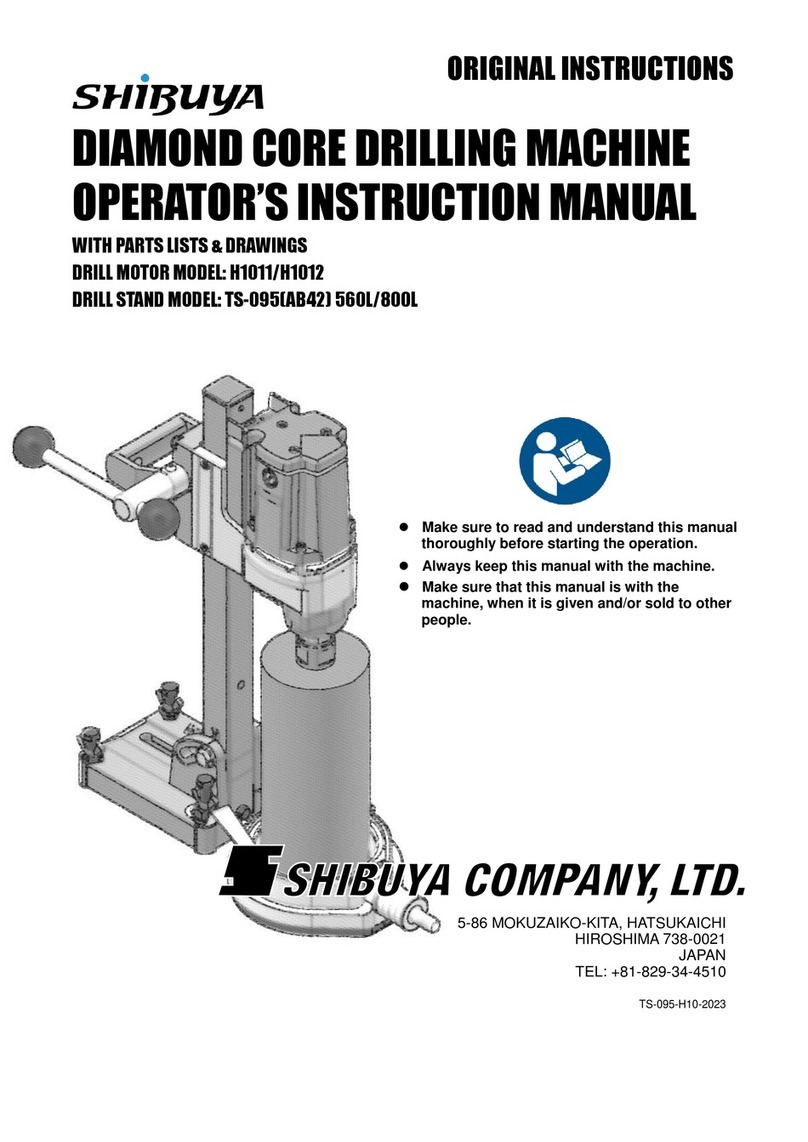
DIAMOND CORE DRILLING MACHINE
OPERATOR’S INSTRUCTION MANUAL
WITH PARTS LISTS & DRAWINGS
DRILL MOTOR MODEL: H2021
DRILL STAND MODEL: TS-255 800L/TS-255 1000L/TS-255(AB52) 1000L
Make sure to read and understand this manual
thoroughly before starting the operation.
Always keep this manual with the machine.
Make sure that this manual is with the
machine, when it is given and/or sold to other
people.
5
-
86 MOKUZAIKO
-
KITA, HATSUKAICHI
HIROSHIMA 738-0021
JAPAN
TEL: +81-829-34-4510
TS-255-H2021-2023
ORIGINAL INSTRUCTIONS

i
NAME OF EACH PART
H2021 Drill Motor
1. Gear Box
2. Motor
3. Spindle
4. Grease Inlet
5. GARDENA Connector /
Water Cock
6. Main Switch
(Circuit Protector)
7. Swivel Ring
8. Gear Change Knob
9. Air Inlet
10. Air Outlet
11. Power Cord
12. Water Leakage Hole
13. PRCD (220-240 V model only)
14. Carriage Block
15. Stopper-Knob (Carriage Brake)
16. Grip Handle
17. Quick Release Handle (Feed Handle)
TS-255 Drill Stand
18. Column
19. Anchor Slot
20. Leveling Bolt
21. Base
22. Beam
23. U-Nut
TS-255(AB52) Drill Stand
1.
Hex Bolt M12x90 7. Angle Scale
2.
U-Nut 8. Leveling Bolt
3.
Beam 9. Flange Nut
4.
Indication label 10.
Base
5.
Hex Bolt M12x70 11.
Anchor Slot
6.
Plate
Refer to the schematic drawings and parts lists attached at the end of this manual for names of more
specific parts.
15
16
19
20
14
17
18
21
22
23
3
5
2
1
4
6
9
8
7
10
11
12
1
3
2
5
4
7
6
9
8
10
10
11
13

ii
ILLUSTRATIONS OF OPERATION
(The numbers in the figure correspond to the same heading number in the writing sections.)
7.1
7.1 7.1
7.2 7.2
6
79
With 30
mm s
pacer:
290
mm
(1
1.4
”
)
Without 30 mm spacer: 260 mm (10.2”)
8
6
7
9
With 30
mm s
pacer:
300
mm
(1
1.8
”
)
Without 30 mm spacer: 270 mm (10.6”)
8
1
2
3
5
4

iii
7.3.1
7.3.2 7.3.2
7.3.3 7.3.3
1
1 2
1
2
3
4
2 4
5
6 3

iv
7.4
7.5
7.6 7.7
1
2
1
2
3
4
1
2
3

v
8.2.1
8.2.1
8.2.1
ON
3
2
4 5

vi
STANDARD ACCESSORIES
Check that all of the following items are included in the package.
TS-255
Item Size Qty.
30 mm Spacer Set 1
Hex. Socket Bolt Spring Washer M8x60 2-8 4 4
Water Collection Rings WCR-180 1
Item in the tool bag Size Qty.
Single-End Spanner 21 mm 1
Single-End Spanner 36 mm 1
Allen Key 4 mm 1
Allen Key 6 mm 1
Square Washer W3/8 1
Core Removal Lasso 1
TS-255(AB52)
Item Size Qty.
30 mm Spacer Set 1
Hex. Socket Bolt Spring Washer M8x60 2-8 4 4
Water Collection Rings WCR-180 1
Item in the tool bag Size Qty.
Double-End Spanner 17x19 mm 1
Single-End Spanner 36 mm 1
Allen Key 4 mm 1
Allen Key 6 mm 1
Square Washer W3/8 1
Core Removal Lasso 1

vii
CONTENTS
NAME OF EACH PART .......................................................................................................................................
ⅰ
ILLUSTRATIONS OF OPERATION.....................................................................................................................
ⅱ
STANDARD ACCESSORIES
...........................................................................................................................................
ⅵ
CONTENTS
.......................................................................................................................................................................
ⅶ
1.
GENERAL INFORMATION..........................................................................................................................
1
1.1
Safety notes and their meanings ..........................................................................................................................1
1.2
Pictograms............................................................................................................................................................1
1.3
Model name plate label.........................................................................................................................................2
1.4
Other label............................................................................................................................................................2
2.
DESCRIPTION ............................................................................................................................................
3
2.1
Applications of the machine..................................................................................................................................3
3.
IMPORTANT NOTICE .................................................................................................................................
3
4.
SAFETY.......................................................................................................................................................
4
4.1
Safety precautions................................................................................................................................................4
4.1.1
General power tool safety warnings .............................................................................................................4
4.1.2
Diamond drill safety warnings ......................................................................................................................5
4.1.3
Additional safety precautions .......................................................................................................................6
4.2
Safety devices ......................................................................................................................................................7
5.
TECHNICAL DATA ......................................................................................................................................
8
5.1
Diamond core drilling machine .............................................................................................................................8
5.2
Noise information and vibration values determined in accordance with EN 62841...............................................9
6.
BEFORE USE............................................................................................................................................
10
6.1
Connecting the drill motor with the 30 mm spcer to the carriage block...............................................................10
6.2
PRCD, GFCI and RCD .......................................................................................................................................10
6.3
Extension cords ..................................................................................................................................................11
7.
SETTING UP ..............................................................................................................................................
11
7.1
Fastening the drill stand with an anchor .............................................................................................................11
7.2
Adjusting the angle of the drill stand with AB52 ..................................................................................................12
7.3
Mounting the drill motor with the carriage block on the drill stand ......................................................................12
7.3.1
Attaching the quick release handle to the carriage block ...........................................................................12
7.3.2
Attaching the drill motor with the carriage block to the drill stand...............................................................12
7.3.3
Adjusting the carriage block .......................................................................................................................13
7.4 Attaching a core bit.............................................................................................................................................13
7.5
Shifting the gear..................................................................................................................................................14
7.6
Setting a water collection ring.............................................................................................................................14
7.7
Preparation for water supply...............................................................................................................................15
8.
OPERATION..............................................................................................................................................
15
8.1
Precautions for the drilling operation ..................................................................................................................15
8.1.1
General ......................................................................................................................................................15
8.1.2
Electrical safety ..........................................................................................................................................15
8.1.3
Others ........................................................................................................................................................16
8.2
Operating procedure...........................................................................................................................................16
8.2.1
Start drilling ................................................................................................................................................16
8.2.2
Restart after the circuit protector trips.........................................................................................................16
8.2.3
Core bit jamming ........................................................................................................................................16
8.2.4
Stop drilling.................................................................................................................................................17
8.2.5
Remove cores with the core removal lasso................................................................................................17
9.
CLEANING ................................................................................................................................................
17
10.
ACCESSORIES (OPTION)........................................................................................................................
18
11.
MAINTENANCE.........................................................................................................................................
18
11.1
Replacing the carbon brushes............................................................................................................................18

viii
12.
TRANSPORT AND STORAGE..................................................................................................................
18
13.
TROUBLESHOOTING...............................................................................................................................
19
14.
DISPOSAL.................................................................................................................................................
20
15.
LIMITED WARRANTY ...............................................................................................................................
20
16.
DIMENSIONS ............................................................................................................................................
20
17.
PARTS LIST...............................................................................................................................................
21

1
1. GENERAL INFORMATION
1.1 Safety notes and their meanings
In this manual, warning signs are classified into four levels based on the level of potential risks.
This symbol indicates the imminent risks that lead to death or serious injury to the
operators and others, unless the safety instructions are observed.
This symbol indicates the potential risks that may lead to death or serious injury to
the operators and others, unless the safety instructions are observed.
This symbol indicates the potential risks that lead to injury to the operators and
others, unless the safety instructions are observed.
This symbol is used for the information that is necessary for you to know.
1.2 Pictograms
Make sure to read and understand this manual thoroughly before starting the
operation.
The machine can be a dangerous tool if it is not used correctly. Incorrect and
careless use can lead to death or serious injury to the operators and/or others.
Do not dispose of this machine with domestic waste. Follow your national law.
When you dispose of concrete slurry, ask your local authorities for applicable
regulations.
DANGER
WARNING
CAUTION
NOTE

2
1.3 Model name plate label
This machine has a label as shown in the figures below. When the label is illegible or lost, contact a
Shibuya authorized dealer to get a new one.
The serial number on the model name plate indicates the production year and month of the drill motor
as shown in the sample below.
Model Name Plate Label
SERIAL (sample): 18 Z 0001
Serial No.
Month (Jan.-Sep.= 1-9, Oct.=X, Nov.=Y, Dec.=Z)
Year (2018)
110 V model 110-120 V model 220-240 V model
1.4 Other label
This machine has labels as shown in the figure below. When the label is illegible or lost, contact a
Shibuya authorized dealer to get a new one.
Dealer Label (CE and US version only)
Carriage Block Label
Weight Label

3
2. DESCRIPTION
This machine consists of the drill motor and drill stand. This machine is designed for wet drilling in
walls and floors made of concrete, natural stone and other mineral building materials using diamond
core bits (diamond tools). The drill motor must be mounted on a Shibuya drill stand: TS-255 800L,
TS-255 1000L, or TS-255(AB52) 1000L. Handheld use is not permissible.
2.1 Applications of the machine
Drilling reinforced concrete for piping works
Extracting concrete cores for strength testing
Overall drilling in reinforced concrete, except drilling upwards
3. IMPORTANT NOTICE
DANGER
Improper use of the diamond core drilling machine may lead to serious or fatal injuries.
Read, understand and follow this manual carefully before the operation.
This machine is designed for core drilling operations. Never use it for any other purposes.
Do not use it as a hand-held core drill.
WARNING
This machine is intended for industrial applications by experienced operators.
Always use common sense and plan your work to avoid injuries. It is not possible to cover
all risks which may occur during the operations in this manual. Therefore, enough care
must be taken to ensure the safe operation of this machine.
NOTE
Shibuya Company, Ltd. reserves the right to change specifications of products without any prior
notices.
Copyright reserved on this manual. Publication of the technical information and drawings in this
manual, and duplication without prior permission of Shibuya Company, Ltd. is prohibited.

4
4. SAFETY
4.1 Safety precautions
The safety precautions given in the following section contain all general safety precautions for power
tools which, in accordance with the applicable standards, require to be listed in the operating
instructions.
Accordingly, some of the rules listed may not be relevant to this power tool.
4.1.1 General power tool safety warnings
WARNING
Read all safety warnings, instructions, illustrations and specifications provided with this
power tool. Failure to follow all instructions listed below may result in electric shock, fire and/or
serious injury.
Save all warnings and instructions for future reference.
The term "power tool" in the warnings refers to your mains-operated (corded) power tool or
battery-operated (cordless) power tool.
1) Work area safety
a) Keep work area clean and well lit. Cluttered or dark areas invite accidents.
b) Do not operate power tools in explosive atmospheres, such as in the presence of
flammable liquids, gases or dust. Power tools create sparks which may ignite the dust or
fumes.
c) Keep children and bystanders away while operating a power tool. Distractions can cause
you to lose control.
2) Electrical safety
a) Power tool plugs must match the outlet. Never modify the plug in any way. Do not use any
adapter plugs with earthed (grounded) power tools. Unmodified plugs and matching outlets
will reduce risk of electric shock.
b) Avoid body contact with earthed or grounded surfaces, such as pipes, radiators, ranges
and refrigerators. There is an increased risk of electric shock if your body is earthed or
grounded.
c) Do not expose power tools to rain or wet conditions. Water entering a power tool will
increase the risk of electric shock.
d) Do not abuse the cord. Never use the cord for carrying, pulling or unplugging the power
tool. Keep cord away from heat, oil, sharp edges or moving parts. Damaged or entangled
cords increase the risk of electric shock.
e) When operating a power tool outdoors, use an extension cord suitable for outdoor use.
Use of a cord suitable for outdoor use reduces the risk of electric shock.
f) If operating a power tool in a damp location is unavoidable, use a residual current device
(RCD) protected supply. Use of an RCD reduces the risk of electric shock.
3) Personal safety
a) Stay alert, watch what you are doing and use common sense when operating a power tool.
Do not use a power tool while you are tired or under the influence of drugs, alcohol or
medication. A moment of inattention while operating power tools may result in serious personal
injury.
b) Use personal protective equipment. Always wear eye protection. Protective equipment such
as a dust mask, non-skid safety shoes, hard hat or hearing protection used for appropriate
conditions will reduce personal injuries.
c) Prevent unintentional starting. Ensure the switch is in the off-position before connecting
to power source and/or battery pack, picking up or carrying the tool. Carrying power tools
with your finger on the switch or energising power tools that have the switch on invites accidents.
d) Remove any adjusting key or wrench before turning the power tool on. A wrench or a key
left attached to a rotating part of the power tool may result in personal injury.

5
e) Do not overreach. Keep proper footing and balance at all times. This enables better control
of the power tool in unexpected situations.
f) Dress properly. Do not wear loose clothing or jewellery. Keep your hair and clothing away
from moving parts. Loose clothes, jewellery or long hair can be caught in moving parts.
g) If devices are provided for the connection of dust extraction and collection facilities,
ensure these are connected and properly used. Use of dust collection can reduce
dust-related hazards.
h) Do not let familiarity gained from frequent use of tools allow you to become complacent
and ignore tool safety principles. A careless action can cause severe injury within a fraction of
a second.
4) Power tool use and care
a) Do not force the power tool. Use the correct power tool for your application. The correct
power tool will do the job better and safer at the rate for which it was designed.
b) Do not use the power tool if the switch does not turn it on and off. Any power tool that
cannot be controlled with the switch is dangerous and must be repaired.
c) Disconnect the plug from the power source and/or remove the battery pack, if detachable,
from the power tool before making any adjustments, changing accessories, or storing
power tools. Such preventive safety measures reduce the risk of starting the power tool
accidentally.
d) Store idle power tools out of the reach of children and do not allow persons unfamiliar
with the power tool or these instructions to operate the power tool. Power tools are
dangerous in the hands of untrained users.
e) Maintain power tools and accessories. Check for misalignment or binding of moving
parts, breakage of parts and any other condition that may affect the power tooI’s
operation. If damaged, have the power tool repaired before use. Many accidents are caused
by poorly maintained power tools.
f) Keep cutting tools sharp and clean. Properly maintained cutting tools with sharp cutting edges
are less likely to bind and are easier to control.
g) Use the power tool, accessories and tool bits etc. in accordance with these instructions,
taking into account the working conditions and the work to be performed. Use of the power
tool for operations different from those intended could result in a hazardous situation.
h) Keep handles and grasping surfaces dry, clean and free from oil and grease. Slippery
handles and grasping surfaces do not allow for safe handling and control of the tool in
unexpected situations.
5) Service
a) Have your power tool serviced by a qualified repair person using only identical
replacement parts. This will ensure that the safety of the power tool is maintained.
4.1.2 Diamond drill safety warnings
a) When performing drilling that requires the use of water, route the water away from the
operator’s work area or use a liquid collection device. Such precautionary measures keep
the operator’s work area dry and reduce the risk of electrical shock.
b) Operate power tool by insulated grasping surfaces, when performing an operation where
the cutting accessory may contact hidden wiring or its own cord. Cutting accessory
contacting a “live” wire may make exposed metal parts of the power tool “live” and could give the
operator an electric shock.
c) Wear hearing protection when diamond drilling. Exposure to noise can cause hearing loss.
d) When the bit is jammed, stop applying downward pressure and turn off the tool.
Investigate and take corrective actions to eliminate the cause of the bit jamming.
e) When restarting a diamond drill in the workpiece check that the bit rotates freely before
starting. If the bit is jammed, it may not start, may overload the tool, or may cause the diamond
drill to release from the workpiece.
f) When securing the drill stand with anchors and fasteners to the workpiece, ensure that the
anchoring used is capable of holding and restraining the machine during use. If the
workpiece is weak or porous, the anchor may pull out causing the drill stand to release from the
workpiece.
g) When drilling through walls or ceilings, ensure to protect persons and the work area on
the other side. The bit may extend through the hole or the core may fall out on the other side.

6
h) Do not use this drill tool for overhead drilling with water supply. Water entering the power
tool will increase the risk of electric shock.
4.1.3 Additional safety precautions
Personal safety
Tampering with or modification of the machine is not permitted.
The machine is not intended for use by inexperienced persons who have received no special
training.
Keep the machine out of reach of children.
Avoid touching rotating parts. Switch the machine on only after it is in the position at the
workpiece. Touching rotating parts, especially rotating accessory tools, may lead to injury. Use
“30mm spacer set” to avoid the feed handle touching to the core bit when using from 200 to 250
mm diameter core bit.
Avoid skin contact with drilling slurry.
Dust from materials, such as paint containing lead, some kinds of wood, concrete / masonry /
stone containing silica, and minerals as well as metal, may be injurious to health. Contact with or
inhalation of the dust may cause allergic reactions and/or respiratory or other diseases to the
operator or bystanders. Certain kinds of dust are classified as carcinogenic such as oak and
beech dust, especially in conjunction with additives for wood conditioning (chromate, wood
preservative). Material containing asbestos must only be handled by specialists. Use a dust
removal system that is as effective as possible. Accordingly, use a suitable vacuum cleaner of the
type recommended by specialists for wood dust and/or mineral dust and which is designed for
use with this power tool. Ensure that the workplace is well ventilated. The use of a dust mask
suitable for the particular type of dust is recommended. Observe national regulations applicable
to the materials on which you intend to use the machine.
The diamond core drilling machine and the diamond core bit are heavy pieces of equipment.
There is a risk of crushing parts of the body. The user and any other persons in the vicinity
must wear suitable eye protection, a hard hat, ear protection, protective gloves and safety
footwear while the machine is in use.
Careful handling and use of electric tools
Make sure that the drill motor is correctly fastened in the drill stand.
Ensure that the accessory tools used have a spindle thread that is compatible with the drilling
machine and that they are secured in the spindle correctly.
Electrical safety
Avoid using extension cords with multiple power outlets and the simultaneous use of several
machines connected to one extension cord.
Never plug into the socket that is not equipped with an earth (ground) conductor.
Before beginning work, check the working area (e.g. using a metal detector) to ensure that
no concealed electric cables or gas and water pipes are present. External metal parts of the
machine may become live, for example, when an electric power line is damaged accidentally.
This presents a serious risk of electric shock.
Make sure that the supply cord is not pinched and damaged as the carriage block advances.
Never operate the machine without the PRCD. Never operate machines without an isolating
transformer if PRCD is not equipped. Test the PRCD each time before use.
Check the machine’s supply cord at regular intervals and have it replaced by a qualified
specialist if found to be damaged. If the machine’s supply cord is damaged it must be replaced by
Shibuya authorized dealer. Check extension cords at regular intervals and replace them if found
to be damaged. Do not touch the supply cord or extension cord if it is damaged while working.
Disconnect the supply cord plug from the power outlet. Damaged supply cords or extension cords
present a risk of electric shock.
Workplace
Approval must be obtained from the site engineer or architect prior to beginning drilling
work. Drilling work on buildings and other structures may influence the static equilibrium of the
structure, especially when steel reinforcing bars or load-bearing components are cut through.
If the drill stand has not been fastened correctly, always move the drill motor mounted on the drill

7
stand all the way down in order to prevent the stand from falling over.
Keep the supply cord, extension cord, water hose and vacuum hose away from rotating parts of
the machine.
4.2
Safety devices
Circuit protector (Main Switch)
WARNING
Do not modify the circuit protector.
This machine is equipped with a circuit protector for safer operation, avoiding overload of the drill
motor which may cause fire or smoke.
Clutch system
CAUTION
Do not tighten the clutch by yourself.
This machine is equipped with clutch system to reduce the risks when the core bit is jammed. This
system also plays a role in protecting the power train.

8
5. TECHNICAL DATA
5.1
Diamond core drilling machine
When powered by a generator or transformer, the generator or transformer’s power output must be at
least 4.0 kVA (100 V), 3.5 kVA (110-120 V) or 5.2 kVA (220-240 V). The operating voltage of the
transformer or generator must always be the voltage stated on the model name plate label.
The specification may vary for country-specific versions. Please refer to the model name plate label
for details of its voltage, frequency, current and input power ratings.
Information for users as per EN 61000-3-11: Switching on causes a brief drop in voltage. Other
appliances may be negatively affected on mains supplies where conditions are unfavorable. No
malfunctions are to be expected in mains supplies with an impedance of less than 0.162 ohms
(220-240 V).
Motor Model H2021
Rated Voltage (V) 100 110 / 110-120 220-240
Rated Frequency (Hz)
50/60
Rated Input (W) 2700 2300 3450
Rated Current (A) 27 20 15
Spindle Rev. at No Load (min
-
1
)
470/1050 450/950 550/1200
Spindle Rev. at Rated Load (min
-
1
)
320/720 310/680 300/730
Spindle Thread UNC 1 1/4” or A-ROD
Weight (
incl. C
arri
a
g
e B
l
ock
excl. Plug and Cord)
(kg)
12.2 (26.9 lbs.)
NOTE
Never use the machine at the place where the ambient temperature is below 0 degrees C (32 degrees
F) or above 40 degrees C (104 degrees F).
Drill Stand Model TS-255(800L/1000L)
TS-255(AB52)
Max. Applicable Core Bit Diameter
w/ 30 mm Spacer (mm)
250 (10”)
Overall Height (mm)
803 (31.6”)/1003 (39.5”)
1011 (40”)
Base Size (mm)
158 x 217 (6.2” x 8.5”)
146 x 205 (5.7” x 8.1”)
Total Stroke (mm)
493 (19.4”)/693 (27.3”)
680 (26.8”)
Max Column Tilt Angle (°)
- 45
Weight (kg)
6.6 (14.6 lbs.)/
7.5 (16.5 lbs.) 7.2 (15.9 lbs.)

9
5.2
Noise information and vibration values determined in accordance with EN
62841
The sound pressure and vibration values given in these instructions have been measured in
accordance with a standardized test and may be used to compare one power tool with another. They
may be used for a preliminary assessment of exposure. The data given represents the main
applications of the power tool. However, if the power tool is used for different applications, with
different accessory tools, or is poorly maintained, the data may vary. This may significantly increase
exposure over the total working period. An accurate estimation of exposure should also take into
account the times when the power tool is switched off, or when it is running but not actually being
used for a job. This may significantly reduce exposure over the total working period. Identify
additional safety measures to protect the operator from the effects of noise and/or vibration, for
example: maintain the tool and the accessories and organization of work patterns.
The sound pressure and vibration have been measured under the following condition in accordance
with EN62841.
Drill motor Speed range Core bit dia. Concrete formulation
H2021
(110 / 220-240 V)
L
(Low speed) 200 mm The water/cement mass ratio : 0.56
Compressive strength : 44 N/mm2
Noise emission values determined in accordance with EN 62841
Total vibration (vector sum of three directions) measured in accordance with EN 62841
Triaxial total vibration (vector sum of vibration) at the quick release handle (feed handle) does
not exceed 2.5 m/s² in accordance with EN 62841.
Drill motor H2021 110 V
Sound (power) level (LWA) 102.6 dB(A)
Uncertainty for the sound power level (KWA) 3 dB(A)
Sound pressure level (LpA) 86.6 dB(A)
Uncertainty for the sound pressure level (KpA) 3 dB(A)
Drill motor H2021 220-240 V
Sound (power) level (LWA) 105.9 dB(A)
Uncertainty for the sound power level (KWA) 3 dB(A)
Sound pressure level (LpA) 90.9 dB(A)
Uncertainty for the sound pressure level (KpA) 3 dB(A)

10
6. BEFORE USE
When you purchase a complete set that consists of Drill Motor and Drill Stand, the packing is divided
into two packages. The drill motor H2021 (including carriage block) in the polyethylene bag is packed
in the carton box. The drill stand TS-255(800L/1000L) is packed in the carton box. The drill stand
TS-255(AB52) is packed in the carton box. Assemble the components as described in this manual
after unpacking.
6.1 Connecting the drill motor with the 30 mm spacer to the carriage block
WARNING
Make sure the drill motor is switched off and disconnected from the power supply.
Comply with the tightening torque stated on this manual. Inadequate torque may lead to
death or serious injury to the operators and others.
Remove 4 pieces of hex. socket bolts (M8x30) fixing the drill motor and the carriage block.
Use 4 pieces of hex. socket bolts (M8x60) and 4 pieces of spring washers (2-8) which are supplied
with the 30 mm spacer. The tightening torque is 35 Nm (25 lbf・ft) each.
Refer to the figure below.
Carriage Block
Hex. Socket Bolt (M8x60)
Spring Washer (2-8)
30 mm Spacer
Drill Motor
6.2 PRCD, GFCI and RCD
220-240 V model
WARNING
Always use a Portable Residual Current Device (PRCD) also known as a Ground Fault Circuit
Interrupter (GFCI).
Test and reset the PRCD before each use.
1. Plug into an earthed/grounded power outlet.
2. Press the "I" or "RESET" button on the PRCD.
The indicator lights up.
3. Press the "0" or "TEST" button on the PRCD.
The indicator goes out.
100-120 V model
WARNING
Always use a Residual Current Device (RCD) also known as a Ground Fault Circuit Interrupter
(GFCI).
Refer to the manual of the RCD or GFCI.
Specifications of an RCD or GFCI
Power voltage 100-120 V
Breaking current 30 A or more
Current leakage 10 mA or less

11
6.3 Extension cords
CAUTION
For 220-240 V model, use only extension cords of a type approved for the application and
with conductor cross section 2 mm2or larger, and the maximum allowable length of the
cord is 35 meters (115 ft).
For 110-120 V model, use only extension cords of a type approved for the application and
with conductor cross section 2.5 mm2(12AWG) or larger, and the maximum allowable
length of the cord is 30 meters (98 ft).
For 100 V model, use only extension cords of a type approved for the application and with
conductor cross section 3.5 mm2(12AWG) or larger, and the maximum allowable length of
the cord is 30 meters (98 ft).
Never turn on the drill motor while the extension cords are circularly bundled. The
circularly bundled extension cords may act as a coil which generates a magnetic field and
heat.
7. SETTING UP
7.1 Fastening the drill stand with an anchor
DANGER
Fasten the drill stand firmly on the material to be drilled, otherwise the machine may become
unstable during the operation and it may lead to death or serious injury to the operators and
others.
WARNING
Read and follow the instruction manual of the anchor bolts used with the machine.
Use anchor bolts which tensile strength is greater or equal to 24.5 kN (5.5 klbf).
When fastening the drill stand to a wall, countermeasures must be taken to avoid falling
hazards.
Never fasten the drill stand to a ceiling.
1) Drill a hole for Drop-In anchor, using a hammer drill.
The ideal distance between the center of the hole to be drilled and the anchor hole;
TS-255 fixed base drill stand
a) With 30 mm spacer: 300 mm (11.8”)
b) Without 30 mm spacer: 270 mm (10.6”)
TS-255(AB52) swivel base drill stand
a) With 30 mm spacer: 290 mm (11.4”)
b) Without 30 mm spacer: 260 mm (10.2”)
2) Clean out the anchor hole.
3) Insert the anchor into the hole, and hammer a setting tool to fasten the anchor firmly.
4) Screw a threaded bolt into the anchor.
5) Set the drill stand, passing the bolt through the anchor slot.
6) Insert the W3/8 square washer (standard accessory) to the bolt.
7) Insert a hex. nut to the bolt. Then, tighten the nut temporarily.
8) Adjust the leveling bolts to stabilize the base. Tighten the nut on the leveling bolts to fix the leveling
bolts firmly.
9) Tighten the hex. nut firmly using a spanner.
This manual suits for next models
3
Table of contents
Other Shibuya Drill manuals

