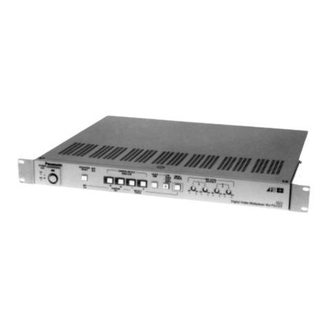
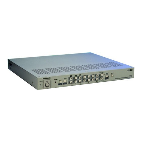
Datacom DM16E1 User manual

DM16E1-DM4E1
DM16E1-DM4E1
INSTALLATION AND OPERATION MANUAL
204-4001-19 Release. 19 Date: 16/1/2009

WARRANTY
This product is guaranteed to be free against manufacturing and raw material defects, during the period
specified in the sales receipt.
The warranty includes only the repair and replacement of components or defective parts, free of charge.
The warranty does not cover damages caused by any one of the following conditions: improper use,
energy failures, natural phenomena (lightning, for example), failure in equipments connected to this
product, improper grounding or repairs done by DATACOM unauthorized personnel.
This warranty does not cover repairs done at the customer’s site. All equipments must be sent to
DATACOM to be repaired.
Quality Management System
certified by DQS according to ISO9001
Register number (287097 QM)
Although this document has been written with care, the company does not assume responsibility for
occasional mistakes and omissions in its content. Likewise, DATACOM is not liable for any damages that
may result from the use of the information contained in this manual. Specifications provided in this manual
are subject to changes without any previous notice and should not be construed as a commitment of any
kind by DATACOM.

CONTACTS
In order to contact the DATACOM technical support, or sales department:
•Support
oE-mail: [email protected]
oPhone: +55 51 3358-0122
oFax: +55 51 3358-0101
•Sales
oE-mail: [email protected]
oPhone: +55 51 3358-0100
oFax: +55 51 3358-0101
•Internet
owww.datacom.ind.br
•Address
oDATACOM
oAv. França, 735 - Porto Alegre, RS - Brasil
oZip Code: 90230-220

CONVENTIONS
In order to improve the agreement, the following conventions are made throughout this manual:
hyperlink - Indicates an internet site or an e-mail address.
Command or Button - Always that some reference to a command, a button or a software menu is made,
this indication will be in italic.
#Commands and messages from terminal screens are presented in not-formatted
text, preceded from #.
Notes give an explanation about some topic in the foregoing paragraph.
This symbol means that this text is very
important and, if the orientations were not correct followed, it may
cause damage or hazard.
This symbols means that, case the procedure was not correctly followed, may exist electrical shock risk.
Represents laser radiation. It is necessary to avoid eye and skin exposure.
Indicates that an equipment or a part is ESDS (Electrostatic Discharge Sensitive). It should not be handled
without grounding wrist strap or equivalent.
Non-ionizing radiation emission.
IWEEE Directive Symbol
(Applicable in the European Union and other European countries with separate
collection systems).This symbol on the product or its packaging indicates that this product must not be
disposed of with other waste. Instead, it is yo
ur responsibility to dispose of your waste equipment by
handing it over to a designated collection point for the recycling of waste electrical and electronic
equipment. The separate collection and recycling of your waste equipment at the time of disposal w
ill help
conserve natural resources and ensure that it is recycled in a manner that protects human health and the
environment. For more information about where you can drop off your consumer waste equipment for
recycling, please contact your local city rec
ycling office or the dealer from whom you originally purchased
the product.

TELECOMMUNICATION SAFETY
Telecommunication network interfaces are classified according to their circuit characteristics. The following
table lists the status of safety circuit characteristics of several standard interfaces. If the safety
characteristic of a given interface type differs from the standard one, a notice will be given in the
equipment manual.
Safety Interface Types Description
SELV V.35, V.36/V.11, V.24/V.28
10Base-T, 100Base-T,
1000Base-T, 1000Base-TX,
1000Base-SX, G64, E1, E3,
STM-1, Voice E&M
Safety Extra Low Voltage
Ports which do not present hazardous voltages.
Voltages up to 42,4V peak or 60Vd.c.
TNV-1 none Telecommunication Network Voltage -1:
Ports whose normal operation voltages do not exceed the limits of SELV
,
on which overvoltages from telecommunications networks system
are
possible.
TNV-2 FXO Telecommunication Network Voltage - 2:
Ports whose normal operation voltages exceed the limits of SELV
(usually
up to 71V peak or 120Vd.c.), on which overvoltages from
telecommunications networks system are not possible.
TNV-3 FXS, xDSL Telecommunication Network Voltage - 3:
Ports whose normal operation voltages exceed the limits of SELV
(usually
up to 71V peak or 120Vd.c.), on which overvoltages from
telecommunications networks system are possible.
Some SELV and TNV circuits use the same
connectors. To avoid electric shock, do not connecting SELV
to TNV circuits.

INDEX
1. INTRODUCTION....................................................................................... 11
1.1. Aggregate Interfaces Available........................................................................12
1.1.1. Aggregate Optics...................................................................................................................12
1.1.2. Electric Aggregates................................................................................................................12
1.2. E2 and E3 Multiplexing Principle.....................................................................12
1.3. Ethernet Remote Bridge..................................................................................13
2. TECHNICAL SPECIFICATIONS............................................................... 14
2.1. Environmental Conditions................................................................................14
2.2. Supply Unit......................................................................................................14
2.3. Consumption...................................................................................................14
2.4. Dimensions .....................................................................................................15
2.5. Weight.............................................................................................................15
2.6. Front and Rear Panels ....................................................................................15
2.7. Led Indicators..................................................................................................16
2.8. Equipment Interfaces.......................................................................................16
2.9. Applicable Norms............................................................................................17
3. MANAGEMENT VIA THE TERMINAL PORT ........................................... 18
3.1. PC or Terminal Connection .............................................................................18
3.2. Introduction .....................................................................................................18
3.3. Configurations for Management via the Terminal Port.....................................19
3.4. Configurations of the Terminal Serial Interface................................................19
3.5. Trial Operation.................................................................................................20
3.6. Main Terminal Screen .....................................................................................21
3.7. Option Choose Equipment to Configure..........................................................22
3.8. Equipment Main Menu.....................................................................................24
3.9. Config Wizard..................................................................................................24
3.10. Settings Menu ...............................................................................................26
3.10.1. General Settings..................................................................................................................28
3.10.2. Interface Selection...............................................................................................................31
3.10.3. Tributary Table.....................................................................................................................32
3.11. Tests Menu ...................................................................................................33
3.12. Status Menu..................................................................................................33
3.12.1. Device Status.......................................................................................................................34
3.12.2. Interface Status Menus........................................................................................................36
3.13. System Parameters.......................................................................................36
4. G.703 TRIBUTARY INTERFACES .......................................................... 38
4.1. General Interface Characteristics ....................................................................38
4.2. Status Indicators for E1 Interfaces...................................................................38
4.3. Electric Characteristics of the G.703 E1 Interface............................................39
4.4. E1 Interface Configurations.............................................................................39
4.5. Configuration Straps........................................................................................39
4.6. Strap Location.................................................................................................40
4.7. Local Analog Loopback – LAL.........................................................................40
4.8. Local Digital Loopback – LDL..........................................................................40
4.9. Terminal Operation..........................................................................................41
4.9.1. Configuration .........................................................................................................................41
4.10. Status............................................................................................................43
4.11. Tests.............................................................................................................44
5. V.35 AND V.36/V.11 DIGITAL INTERFACES........................................... 45
5.1. V.35 Interface..................................................................................................45
5.2. V.36/V.11 Interface..........................................................................................45
5.3. V.35 / V.36/V.11 Selection Straps....................................................................47
5.4. Digital interface signals....................................................................................47
5.5. BERT ..............................................................................................................47

5.6. Local Digital Loopback – LDL..........................................................................48
5.7. Operation via Terminal....................................................................................48
5.7.1. Configuration .........................................................................................................................49
5.7.2. Status ....................................................................................................................................50
5.7.3. Tests......................................................................................................................................51
6. OPTIC INTERFACE CARDS ................................................................... 52
6.1. Optic Aggregate Cards Available:....................................................................52
6.2. Characteristics of Optic E3 Interfaces..............................................................53
6.3. Optic Interface Status Indicators on the Front Panel........................................53
6.4. Optic Interface Configurations.........................................................................54
6.5. Local Analog Loopback – LAL.........................................................................54
6.6. Local Digital Loopback – LDL..........................................................................55
6.7. Operation via terminal .....................................................................................55
6.8. Configuration...................................................................................................55
6.9. Status..............................................................................................................56
6.10. Tests.............................................................................................................57
7. ELECTRIC E3 INTERFACE CARDS ....................................................... 59
7.1. Aggregate Cards - DM16E1-E3E.....................................................................59
7.2. DM16E1-E3Ei Internal Card............................................................................59
7.3. Status of the Electric Aggregate on the Front Panel........................................59
7.4. Status Indicators of the Internal E3 Card.........................................................60
7.5. Electric Characteristics of E3 G.703 Interface .................................................60
7.6. Electric E3 Interface Configurations.................................................................60
7.7. Local Analog Loopback – LAL.........................................................................60
7.8. Local Digital Loopback – LDL..........................................................................61
7.9. Location of Straps in DM16E1-E3E Cards.......................................................61
7.10. Operation via Terminal..................................................................................61
7.11. Configuration.................................................................................................62
7.12. Status............................................................................................................62
7.13. Tests.............................................................................................................63
8. 10/100BASET ETHERNET REMOTE BRIDGE ....................................... 64
8.1. Ethernet Physical Level...................................................................................65
8.2. Operation via Terminal....................................................................................66
8.3. Configuration...................................................................................................66
8.3.1. Inverse Multiplexer Management Configuration.....................................................................68
8.4. Status..............................................................................................................68
8.5. Bridge with packet ordainment (Bridge Packet Sequencing)............................69
8.6. Different Bridge hardware versions for the DM16E1/DM4E1 equipment..........69
8.6.1. SW Change from Bridge_HW1 to Bridge_HW2 or vice-versa ...............................................71
8.6.2. Cards and topologies supported by version with ordainment ................................................71
8.6.3. Setup.....................................................................................................................................72
8.6.4. Interoperability between Bridge_HW1 and Bridge_HW2.......................................................72
8.6.5. Remote Management............................................................................................................72
9. ROUTING.................................................................................................. 73
9.1. Operation via Terminal....................................................................................74
9.2. WAN1 Port Physical Configurations ................................................................74
9.3. WAN2 Port Physical Configurations ................................................................75
9.4. IP Configurations.............................................................................................77
9.4.1. Ethernet (LAN) Interface Configurations................................................................................77
9.4.2. Generic WAN Configurations.................................................................................................78
9.4.3. Routing General Menus.........................................................................................................79
9.4.4. Router General Options.........................................................................................................79
9.4.5. WAN1 IP Configuration..........................................................................................................80
9.4.6. Configuration of static routes.................................................................................................81
9.4.7. Gateway Default Configuration..............................................................................................82
9.4.8. WAN2 PPP Interface Configurations.....................................................................................82
9.4.9. WAN Frame Relay Interface Configuration............................................................................83
9.4.10. Frame Relay Virtual Circuit Configurations..........................................................................83

9.4.11. Advanced Frame Relay Parameters....................................................................................84
10. STRAPS.................................................................................................... 86
10.1. Connecting the Frame Ground to the Signal Ground.....................................86
10.2. E1 Tributary Channel Straps .........................................................................86
10.3. External Clock Strap......................................................................................86
10.4. V.35 and V.36/V.11 Interface Selection Straps..............................................86
10.5. E3 Electric Interface Card Straps...................................................................87
10.6. Restricted Use Straps....................................................................................87
11. VOICE CHANNEL .................................................................................... 88
11.1. Specifications of the Voice Channel ..............................................................88
12. ALARMS AND EXTERNAL CLOCK ......................................................... 89
12.1. Alarm Inputs..................................................................................................89
12.2. Alarm Outputs ...............................................................................................89
12.3. Input of External Clock ..................................................................................90
12.4. Failure Situations...........................................................................................91
13. MANAGEMENT SYSTEM ........................................................................ 92
13.1. Remote Management....................................................................................92
13.1.1. In Band Management ..........................................................................................................92
13.2. IP Management (Direct IP SNMP).................................................................93
13.3. Management Setup.......................................................................................93
13.3.1. Setup via SNMP ..................................................................................................................93
13.3.2. Ethernet Management.........................................................................................................93
14. SOFTWARE.............................................................................................. 94
14.1. How to Identify the Current Version of the Software ......................................94
14.2. Download via TFTP.......................................................................................94
14.3. Download via the Terminal Port.....................................................................95
15. INSTALLATION ........................................................................................ 96
15.1. Wall and 19” Rack Mounting..........................................................................96
15.2. Optical Connections ......................................................................................96
15.3. DM16E1 / DM4E1 Mixed Operation...............................................................97
15.4. Point to Point Topology .................................................................................97
15.5. Unidirectional Ring Topology (Cascading).....................................................97
15.6. Bidirectional Ring Topology...........................................................................98
15.7. In-Line Topology............................................................................................99
15.8. Optic Modem Topology ...............................................................................100
15.9. Interface Converter Topology......................................................................101
15.10. Transparent Interface Converter Topology................................................102
15.11. Regenerator Topology...............................................................................102
15.12. Ethernet 10/100BaseT Remote Bridge......................................................102
15.13. V.35-V.36/V.11 Interface...........................................................................103
15.14. Routing......................................................................................................103
15.15. Service Channel........................................................................................103
15.16. External 2048kbit/s clock...........................................................................104
15.17. External Alarm...........................................................................................104
15.18. Terminal Connection .................................................................................104
15.19. SNMP Remote Management.....................................................................104
15.20. Power Connections ...................................................................................104
15.21. Straps........................................................................................................105
15.22. Other Important Topics..............................................................................105

FIGURE INDEX
Figure 1. PDH hierarchy................................................................................ 13
Figure 2. Power supply input panel ............................................................... 14
Figure 3. Front panel of the DM4E1 .............................................................. 15
Figure 4. Rear panel of the DM4E1............................................................... 15
Figure 5. Front panel of the DM16E1 ............................................................ 16
Figure 6. Rear panel of the DM16E1 with either IEC or BNC connectors...... 16
Figure 7. Rear panel of the DM16E1 with RJ45 connectors.......................... 16
Figure 8. G.703 E1 interface straps for DM4E1............................................. 40
Figure 9. G.703 E1 interface straps for DM16E1........................................... 40
Figure 10. Local analog loopback at a G.703 interface ................................... 40
Figure 11. Local digital loopback at a G.703 interface..................................... 41
Figure 12. Example of ring topology................................................................ 41
Figure 13. Location of V.35 / V.36/V.11 interface straps ................................. 47
Figure 14. BERT generation and reception at the digital interface .................. 48
Figure 15. Local digital loopback at the digital interface .................................. 48
Figure 16. DM16E1 panel for optic interface card ........................................... 54
Figure 17. Local analog loopback at an optic interface.................................... 54
Figure 18. Local digital loopback at an optic interface..................................... 55
Figure 19. A DM16E1/DM4E1 loopback operating with no failures................. 57
Figure 20. Failure in the main loopback........................................................... 57
Figure 21. Electric E3 interface card panel...................................................... 59
Figure 22. Local analog loopback in an electric E3 interface........................... 61
Figure 23. Local digital loopback in electric E3 interface................................. 61
Figure 24. Strap location ................................................................................. 61
Figure 25. Example of bridge inverse multiplexing.......................................... 65
Figure 26. Bridge card_HW1 View .................................................................. 70
Figure 27. Bridge card_HW2 View .................................................................. 70
Figure 28. Connections in Point to Point topology........................................... 97
Figure 29. Example of bidirectional ring with Regular-Ring topology............... 98
Figure 30. Example of bidirectional ring with Cross-Ring topology.................. 98
Figure 31. Connections in Regular-Ring topology........................................... 99
Figure 32. Connections in Cross-Ring topology .............................................. 99
Figure 33. Example of In-Line topology......................................................... 100
Figure 34. Connections in In-Line topology ................................................... 100
Figure 35. Example of Optic Modem topology.............................................. 101
Figure 36. Example of interface converter..................................................... 102
Figure 37. Example of Regenerator topology................................................ 102

TABLE INDEX
Table 1. Consumption of the basic unit and of each interface card.............. 15
Table 2. Dimensions..................................................................................... 15
Table 3. Weight............................................................................................ 15
Table 4. Pinout of the DM16E1/DM4E1 – PC serial connection................... 18
Table 5. Configurable parameters using the Config Wizard Settings Menu . 25
Table 6. RJ45 connector pinout for G.703.................................................... 38
Table 7. G.703 interface led messages........................................................ 38
Table 8. Pinout for V.35................................................................................ 46
Table 9. Pinout for V.36/V.11 ....................................................................... 46
Table 10. Characteristics of optic interfaces................................................... 53
Table 11. Optic interface led indicators (front panel)...................................... 54
Table 12. Leds indications for electric aggregates (front panel)..................... 60
Table 13. Pinout for RJ45 Ethernet connector................................................ 65
Table 14. IP addresses for private networks .................................................. 73
Table 15. Valid or global IP addresses........................................................... 73
Table 16. Pinout of the DB9 connector for alarm inputs................................. 89
Table 17. Pinout of DB9 connector for alarm output....................................... 89
Table 18. Alarm conditions............................................................................. 90
Table 19. E1C straps...................................................................................... 90
Table 20. Failure indication according to G.751 (ITU-T recommendation for E3
multiplexing) ................................................................................... 91

DM16E1 / DM4E1 Operation and Installation Manual - 204-4001-19 11
1. INTRODUCTION
DM16E1 and DM4E1 are E3, PDH (Plesiochronous Digital Hierarchy) multiplexers.
They can work with electric or optic aggregate interfaces. There are two slots for aggregate cards, which
allow for backup or ring operation.
In addition, the equipment counts on four E1 G.703 ports for tributaries in the DM4E1 model and on 16 E1
G.703 ports in the DM16E1 model. Both models have a V.35-V.36/V.11 port, an Ethernet 10BaseT port
with clearing functions, and the option to install an Ethernet Remote Bridge 10/100BaseT card.
DM16E1 and DM4E1 carry out multiplexing in accordance with G.742 (four E1 for E2 channels) and G.751
(four E2 for E3 channels) ITU-T recommendations.
In the DM16E1 model, E1 tributary interfaces can be supplied with BNC or IEC connectors for 75 ohms or
RJ45 for 120 ohms. The type of connector required should be specified when purchasing.
In the DM4E1 model, E1 tributary interfaces can be supplied with BNC or IEC connectors for 75 ohms. The
type of connector required should be specified when purchasing. RJ45 connectors for 120 ohms are
always supplied with the equipment.
A clock´s external reference is not necessary to operate the equipment. Although, a clock´s external
reference can be supplied in order to generate AIS on E1 channels.
Equipment programming can be carried out via a VT100 terminal or via a standard IBM-PC® computer,
using a VT100 terminal emulation software. The connection of the terminal to the equipment is made with
an RS-232 serial cable.
The equipment can be managed via SNMP either by the Ethernet port, on the front panel, or in band,
utilizing routing or remote management.
SNMP management is also available through the DmView application software, which runs over an HP
Open View platform. The application is able to manage a whole network, making it possible to configure,
check status, carry out tests, etc., in every network equipment.
DM16E1 and DM4E1 are physically constituted of a basic unit for mounting in 19” racks with 1,5 units of
height.
Regarding power supply, they can operate with two units of redundant power operation (Main and
Backup). The supply unit can be AC (93 to 250 V) or DC (36 to 72 V), with automatic selection. The
backup unit is identical to the main unit and is optionally supplied.
Aggregate cards and units can be inserted or removed with the equipment switched on and in operation
(hot swap).
The DM16E1 and DM4E1 equipment have a voice service channel with point-to-point, point-to-point optical
modem, regular ring, regular ring optical modem, cross ring and cross ring optical modem topologies.
There is an RJ11 connector on the front panel for a common telephonic device connection. Once the
telephone is off of the hook, an indication will be activated through sonorous alarm at the remote
equipment. The voice channel operation does not modify the data flow.
The multiplexers enable the performance of local digital and local analog loopbacks (LDL and LAL) on E1
and E3 interfaces, in addition to LDL and BERT on V.35-V.36/V.11 interfaces.
They also allow the removal and insertion of E1 signals in any point of the ring. And are provided with a
relay alarm output.

DM16E1 / DM4E1 Operation and Installation Manual - 204-4001-19 12
The interfaces can be individually configured to be part or not of the alarm equipment logic. It is possible to
configure the use of up to three external alarms in this logic. The external alarms are connected to
DM16E1/DM4E1 by a DB9 connector located at the rear panel. The external alarms can be, for example,
for ambient use (temperature and humidity) or to detect intrusion into the place where the equipment is
installed (intrusion alarm). Both types of alarm (internal or external), when activated, send monitoring
information via the management system.
DM4E1 and DM16E1 have led (light-emitting diodes) indicators on their front panels to inform the
conditions of:
•local alarm.
•active test at any interface.
•functioning/presence of power supply units.
•indication of local or remote telephone off the hook.
•status of aggregate and tributary interfaces.
1.1. Aggregate Interfaces Available
1.1.1. Aggregate Optics
There are a number of aggregate optics card options, combining the following parameters:
•Compatible with both DM16E1 and DM4E1.
•Operating on a pair of fibers or on only one (TX and RX on the same fiber).
•Laser transmission power.
•Type of connector used to connect the fiber optics.
See chapter 6 to obtain more details.
1.1.2. Electric Aggregates
•E3 interface for DM16E1 and DM4E1, operating in accordance with G.703 of 34,368 kbit/s (E3).
1.2. E2 and E3 Multiplexing Principle
DM4E1 and DM16E1 multiplexers are based on G.742 and G.751 recommendations.
The Multiplexing structure is represented in Figure 1:
a) G.742: 4 E1 channels, 2048kbit/s (first order) are multiplexed generating an E2 channel, of
8448kbit/s (second order);
b) G.751: 4 E2 channels are multiplexed generating an E3 channel, of 34.368kbit/s (third order).
It should be observed that it is possible to form E2 channels with first order tributaries containing or not the
G.704 frame structure, provided the rate is 2048kbit/s. Similarly, an E3 channel can be formed by channels
with a frame structure compatible or not with that of G.742, provided the rate is 8448kbit/s.
An interesting thing about PDH multiplexing is the possibility of using different clocks, in terms of phase
and frequency, at each input point. Eventual differences are automatically compensated by the equipment.
However, the clocks must be within the standards established for G.703:
•2048kHz ± 50 ppm (parts per million);
•8448kHz ± 30 ppm;
•34368kHz ± 20 ppm.
The clocks generated internally by DM16E1 and DM4E1 are within the tolerances above.

DM16E1 / DM4E1 Operation and Installation Manual - 204-4001-19 13
In the two multiplexing categories, drop-insert can be configured for tributary channels, so that several
DM4E1 or DM16E1 units can share the same E3 link. Each unit inserts data into channels which are not
used by the others, and this way form an optic ring with 100% utilization of the link. More details can be
found in chapter 15.
Figure 1. PDH hierarchy
1.3. Ethernet Remote Bridge
The equipment can be supplied with an Ethernet Remote Bridge interface card, which implements a
10/100BaseT port via an RJ45 connector located on the rear panel. The connector and led indicators are
always assembled independently from the card itself, and can be added later.
More details about this interface in chapter 8.

DM16E1 / DM4E1 Operation and Installation Manual - 204-4001-19 14
2. TECHNICAL SPECIFICATIONS
2.1. Environmental Conditions
Operational temperatures: 0 to 60°C.
Relative humidity: up to 95% uncondensed.
2.2. Supply Unit
The supply of energy to the equipment is made through a tripolar cable (IEC-320 standard). When using
DC voltage, the cable must be cut near the AC connection plug and connected in such a way that the
central pin of the plug corresponds to the frame ground connection and the other two pins correspond to
power units. Polarity is not important, as shown in Figure 2, below. The body of the equipment is
connected directly to the frame ground.
The equipment can be connected to any voltage within the ranges specified below, without any kind of
manual selection. This is automatically done by the equipment, for both the main and backup units. The
backup unit is optional.
Figure 2. Power supply input panel
2.3. Consumption
To estimate the total consumption of the equipment, add the consumption of the basic unit to the
consumption of the aggregate interfaces used.

DM16E1 / DM4E1 Operation and Installation Manual - 204-4001-19 15
DC AC
DM4E1 11,00 9,00
DM16E1 12,00 9,81
E3 optic 1,80 1,50
Bridge 1,50 1,23
Power (W)
Interface
1,10 0,90
E3 electric
- Aggregate
- Tributary
Table 1. Consumption of the basic unit and of each interface card
2.4. Dimensions
The equipment is mounted in a 19” rack with a height of 1.5 U.
Height
Width
Depth
65mm without rubber base supports
72mm with rubber base supports
435mm without subrack brackets
483mm with subrack brackets
232mm
Table 2. Dimensions
2.5. Weight
Table 3 shows the weights of DM16E1, DM4E1 and respective modules:
DM4E1 3,10
DM16E1 3,40
E3 optic 0,10
Bridge 0,10
Power Supply 0,18
Interface
0,14
E3 electric
- Aggregate
- Tributary
Weight (kg)
Table 3. Weight
2.6. Front and Rear Panels
Figure 3. Front panel of the DM4E1
Figure 4. Rear panel of the DM4E1

DM16E1 / DM4E1 Operation and Installation Manual - 204-4001-19 16
Figure 5. Front panel of the DM16E1
Figure 6. Rear panel of the DM16E1 with either IEC or BNC connectors
Figure 7. Rear panel of the DM16E1 with RJ45 connectors
2.7. Led Indicators
PSU (MAIN and BACKUP): indicate the status of the power unit supplies. When lit, it signals that the
supply is operating normally; when unlit, it shows that there is no unit; when flashing, it indicates a
defective unit, or one which is disconnected from the electric network.
AGGREG (1 and 2): indicates the status of the aggregate interface. Unlit shows that no interface is
present; continually lit shows a synchronized interface; flashing indicates LOS or AIS. More details in item
6.3.
TRIBUTARY (1 to 16 in DM16E1 and 1 to 4 in DM4E1): indicates the status of the equipment E1 G.703
tributaries. The behavior pattern is similar to that of aggregate led indicators. More details in item 4.2.
V.35 (103 and 104): reflects the status of 103 and 104 signals at the V.35 tributary.
ALARM: indicates simultaneously alarms of high and low priority. This indication will remain on until the
alarm is eliminated and the user initiates a command of recognition through the terminal port or via the
DmView SNMP management software. More details in chapter 12.
TEST: indicates that the equipment is undergoing a test. It will remain lit while any interface is executing a
test.
ETH LINK: indicates the presence of a signal at the Ethernet port on the rear panel of the equipment.
CALL: lights up when the service channel telephone is off of the hook; flashes when the equipment
receives a call from the remote equipment.
2.8. Equipment Interfaces
TERMINAL: port RS232 (V.24/V.28) in DB9 female connector, utilized to connect the equipment to the
configuration terminal by means of a serial cable. The pinout description of this connector can be seen in
chapter 15.
PHONE: connection of a fixed telephone with an RJ11 connector using a service channel. Used for
communication between operators during installation and maintenance of the link.
AGGREGATES (AG1 and AG2): two slots for the insertion of aggregate interfaces, either optic or electric.

DM16E1 / DM4E1 Operation and Installation Manual - 204-4001-19 17
V.35-V.36/V.11: DB25 connector with ISO2110 Amd.1 pinout for connection to the V.11 interface at
2048kbit/s, which can be configured to assume the position of any E1 tributary within channels E2 or E3.
More details in chapter 5.
ALARM – IN and OUT: in one DB9 female connector, enables the relay contacts of the alarm, and serves
as an input for external alarms coming from other equipment. To see a description of pinout, consult
chapter 12.
10/100Base-T-Bridge: RJ45 connector for Ethernet Remote Bridge. More details in chapter 8. By this
connector there is a led indicator which shows the establishment of a link. The connectors and the led are
always assembled independently from the bridge card, which is optional.
10BaseT-SNMP: RJ45 connector for the connection of Ethernet network to SNMP management, using the
DmView software. A led indicates the status of the link.
EXTERNAL CLOCK: this BNC (or IEC169/13) connector can be connected to an external clock source of
2048kHz (in accordance with G.703), for use with E1 interfaces.
MAIN and BACKUP: ports for DC or AC voltage, as described in chapter 2.2.
TRIBUTARY (1 to 16 in DM16E1): the equipment can be supplied with RJ45 connectors for an impedance
of 120 ohms, or with BNC or IEC169/13 connectors for 75 ohms. In this case, there are straps for the
connection of the coaxial cable external shield to the frame ground (grounding).
TRIBUTARY (1 to 4 in DM4E1): the equipment can be supplied with BNC or IEC169/13 connectors for 75
ohms. In addition, RJ45 connectors for an impedance of 120 ohms are always present. In the case of 75-
ohm connections, straps are available for the connection of the coaxial cable external shield to the frame
ground (grounding).
2.9. Applicable Norms
ITU-TS: G.651, G.652, G.703, G.742, G.751, G.821, G.823, G.826, G.955, V.11.
Ethernet: IEEE 802.3.
Bridge: IEEE 802.1, 802.1Q Tag-based VLANs, 802.1Q VLAN priority Tag e Port Based VLAN.

DM16E1 / DM4E1 Operation and Installation Manual - 204-4001-19 18
3. MANAGEMENT VIA THE TERMINAL PORT
DM4E1 and DM16E1 can be configured in two ways: via SNMP (DmView software) or via a VT100
Terminal or emulator.
This chapter addresses management via a Terminal port. For information with respect to management via
DmView, please consult the user’s guide that accompanies the DmView application software.
3.1. PC or Terminal Connection
The DM16E1/DM4E1 cards have a DB9 female connector on their front panel for the connection of the
equipment to a PC or Terminal, by means of a cable with a DB9 male connector at the end of the
DM16E1/DM4E1 and a female DB9 or DB25 connector on the end of the PC. The pinout is presented in
the table below:
DB9 (DM16E1/DM4E1 DB9 (PC) DB25 (PC)
pin 2 pin 2 pin 3
pin 3 pin 3 pin 2
pin 5 pin 5 pin 7
Table 4. Pinout of the DM16E1/DM4E1 – PC serial connection
To be sure that this will not happen, measure the voltage between these pins using an AC voltmeter. If a
potency difference is detected, check to see whether the DM16E1/DM4E1 and the PC are duly grounded
and then interconnect the signal ground to the DM16E1/DM4E1 frame ground (see item 10.1). This should
solve the problem. After taking these steps, measure the AC voltage again before connecting the serial
cable.
3.2. Introduction
Management via a Terminal port permits:
•Remotely:
−To configure all equipment interfaces.
−To activate tests on interfaces.
−To check the status of interfaces.
•Locally only:
−To configure SNMP parameters and the equipment network.
−To reconfigure the terminal access password.
−To restart the equipment.
For remote equipment management, it is necessary to connect them to the local equipment via an
aggregate link.
Take care so that there is no difference in potency between pin 5 of DB9 at DM16E1/DM4E1 (signal
ground) and pin 5 of DB9 (or pin 7 of DB25) at the PC/Terminal. If this happens, the serial interfaces of the
equipment and of the PC/Terminal will be damaged.

DM16E1 / DM4E1 Operation and Installation Manual - 204-4001-19 19
3.3. Configurations for Management via the Terminal Port
Always use this system when new equipment is inserted into the ring or in cases when it is necessary to
alter the topology of the operation. For more information about how to connect the serial cable, consult
chapter 3.
Changes in the operation topology may cause the loss of data during configuration since it involves
changes in the interface data flow. New topology configurations may also momentarily or permanently
disconnect the management of ring configurations.
The insertion of new ring topology equipment only causes the loss of data during the physical insertion of
the equipment. Then the backup option is active, the removal of equipment is seen as a failure, and the
loss of data is only momentary. If the equipment has been configured correctly, management should
function normally.
The below described configurations should be made locally (direct connection through the equipment
Terminal port) before field installation:
•All the equipment must be functioning with the same topology configurations. Different topology
configurations alter the normal flow of data, which makes management impossible.
•Correct configuration of MAIN / BACKUP aggregate cards. Errors in this configuration can cause
the isolation of equipment in the ring, or loss of the management link. It is recommended not to
alter factory values for these parameters (MAIN card in slot AG1 and BACKUP card in slot AG2).
•Tests should be deactivated in all aggregates. Test activation in remote aggregates causes the
equipment to ignore management information. Aggregate tests can only be deactivated locally.
3.4. Configurations of the Terminal Serial Interface
The terminal must be configured for 9600bit/s, without flow control, 1 stop bit and without parity bit. When
configuration is done with Windows 2000, it is recommended not to use the HyperTerminal, as it
presents some functional problems on this platform. Therefore, the use of Tera Term Pro, a freeware
software, is recommended. It can be downloaded at the following electronic address:
http://www.vector.co.jp/authors/VA002416/teraterm.html
If possible, the option to send characters automatically (without pressing ENTER) should be selected in the
emulation software.
The Terminal authentication screen is represented below:
#-------------------------------------------------------------------------
# DataCom Telematica – DM16E1 Multiplexer
#
#-------------------------------------------------------------------------
#
#
#
#
# Pass ord: [ ]
#
#
#
#
#
#
#
#
#
#
#
#

DM16E1 / DM4E1 Operation and Installation Manual - 204-4001-19 20
3.5. Trial Operation
Trial equipment may have a limited operational period. The header on the terminal screen indicates the
time remaining for use, in accordance with screen below:
#-------------------------------------------------------------------------
# DataCom Telematica – DM16E1 Multiplexer
# Trial time left:1 Days
#-------------------------------------------------------------------------
#
#
#
#
# Pass ord: [ ]
#
#
#
#
#
#
#
#
#
#
#
#
#
#
The trial period can be finalized either by the terminal or via management. On the terminal, this is done by
entering a specific password, which can be obtained from DATACOM.
The trial finalization password can be used in two ways via the Terminal:
•Remotely: the password is inserted after having selected the equipment to be configured (see
chapter 3.7). The insertion of the password removes the equipment from trial automatically.
•Locally, on the authentication screen of the terminal: when inserting the specific equipment
password (same password for local or remote equipment), the screen presented below is
displayed:
On the authentication screen, the software requests the equipment access password. The default
password is "proxySNMP
". To obtain further information on how to disable or reconfigure the password,
see chapter 3.6.
If the password is lost, contact our Technical Support team to solve the problem, informing the MAC
number of the equipment and the serial number. In order to know the MAC number, please access the
terminal authentication screen and type “l” (lowercase L).
This manual suits for next models
1
Table of contents


