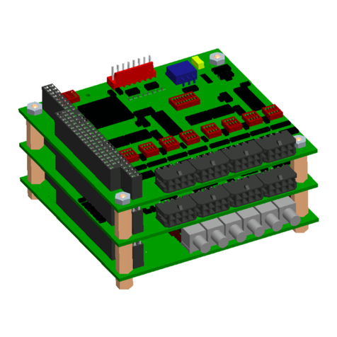
Focal 914-HDE User manual

MOOG PROPRIETARY AND CONFIDENTIAL INFORMATION
THIS TECHNICAL DATA/DRAWING/DOCUMENT CONTAINS INFORMATION THAT IS PROPRIETARY TO, AND IS THE EXPRESS PROPERTY OF MOOG
INC., OR MOOG INC. SUBSIDIARIES EXCEPT AS EXPRESSLY GRANTED BY CONTRACT OR BY OPERATION OF LAW AND IS RESTRICTED TO USE
BY ONLY MOOG EMPLOYEES AND OTHER PERSONS AUTHORIZED IN WRITING BY MOOG OR AS EXPRESSLY GRANTED BY CONTRACT OR BY
OPERATION OF LAW. NO PORTION OF THIS DATA/DRAWING/DOCUMENT SHALL BE REPRODUCED OR DISCLOSED OR COPIED OR FURNISHED
IN WHOLE OR IN PART TO OTHERS OR USED BY OTHERS FOR ANY PURPOSE WHATSOEVER EXCEPT AS SPECIFICALLY AUTHORIZED IN
WRITING BY MOOG INC. OR MOOG INC. SUBSIDIARY.
Focal Technologies Corporation
A Moog Inc. Company
77 Frazee Avenue
Dartmouth, Nova Scotia, Canada B3B 1Z4
Tel: (902) 468-2263 | www.moog.com/focal
Model 914-HDE User Manual
Fiber Optic
HD Video, Data and Ethernet Multiplexer
Document No.:
914-0601-00
Revision:
4.0
Author(s):
EM
Date of Issue:
2017-07-21

Model 914-HDE User Manual
Focal Technologies Corporation ii
A Moog Inc. Company Document Number: 914-0601-00 Rev. 4.0
Document Revision History
Document
Revision
Details of Revision
Author(s)
Date
[yyyy-mm-dd]
Rev 1.0
Initial Release.
EM
2016-02-01
Rev 2.0
Release of B1 and C1 firmware
Ethernet Link Fault Pass Through
Trade HD-SDI for Gigabit Ethernet
Optional input of LED Header
Maximum 350Mb/s Ethernet throughput in M1 mode
while 3G-SDI is plugged
3G-SDI Level B support
Update to colour coded diagnostic cable
EM
2016-06-27
Rev 3.0
Added sections
7.0 Firmware Updates
8.0 Feature Upgrades
EM
2016-10-13
Rev 4.0
Added sections
Quick Start Check List
Troubleshooting Section
VDX Expansion Card
EM
2017-07-21
Reference Documents
Document
Number
Document Title and Description
914-2016-00
Model 914-HDE Configuration Drawing
914-0601-01
Model 914-HDE Diagnostic Protocol Manual
914-2020-00
Model 914 VDX Configuration Drawing
914-0401-00
Model 914 Diagnostic GUI

Model 914-HDE User Manual
Focal Technologies Corporation iii
A Moog Inc. Company Document Number: 914-0601-00 Rev. 4.0
TABLE OF CONTENTS
Introduction.....................................................................................................................................1-1
Setup Check List ............................................................................................................................2-1
System Overview............................................................................................................................3-2
3.1 914-HDE Versions..................................................................................................................3-4
3.2 Power......................................................................................................................................3-5
3.3 HD Video Channel..................................................................................................................3-6
3.4 Serial Data Ports ....................................................................................................................3-7
3.5 Ethernet Port...........................................................................................................................3-8
3.6 Diagnostic LEDs.....................................................................................................................3-9
3.7 Diagnostic LED Header........................................................................................................3-10
3.8 Optics....................................................................................................................................3-11
3.8.1 Flux Budget Calculation...........................................................................................3-11
3.8.2 Optical Safety ..........................................................................................................3-11
Model 914 Diagnostic GUI .............................................................................................................4-1
4.1 Installing the Model 914 Diagnostic GUI ................................................................................4-2
4.1.1 914-HDE Diagnostic Status Display..........................................................................4-4
4.1.2 914-HDE Serial Port Configuration ...........................................................................4-7
4.1.3 914-HDE Ethernet Port Configuration.......................................................................4-7
Expansion Cards............................................................................................................................5-1
5.1 914-VDX.................................................................................................................................5-1
5.1.1 914-VDX Serial Data Ports........................................................................................5-2
5.1.2 914-VDX Composite Video Channels .......................................................................5-1
5.1.3 914-VDX Power.........................................................................................................5-2
5.1.4 914-VDX Diagnostic LEDs ........................................................................................5-3
5.1.5 914-VDX Diagnostic LED Header .............................................................................5-4
5.1.6 914-VDX Expansion Channel Configuration .............................................................5-5
5.1.7 914-VDX Configuration..............................................................................................5-6
5.1.8 914-VDX Serial Port Configuration............................................................................5-7
5.1.9 914-VDX Diagnostics ................................................................................................5-8
5.2 914-EX (Preliminary Information)...........................................................................................5-9
5.3 914-DX (Preliminary Information)...........................................................................................5-9
5.4 Custom ...................................................................................................................................5-9
System Specification .....................................................................................................................6-1
6.1 Example 914-HDE L1 System................................................................................................6-1
6.2 Example 914-HDE M1 System...............................................................................................6-2
6.3 Example 914-HDE H1 System...............................................................................................6-2
Installation and Operation.............................................................................................................7-1
7.1 Installation...............................................................................................................................7-1
7.2 Bench Test..............................................................................................................................7-2
7.3 Electrical and Environmental Specifications...........................................................................7-3
7.4 Maintenance...........................................................................................................................7-3

Model 914-HDE User Manual
Focal Technologies Corporation iv
A Moog Inc. Company Document Number: 914-0601-00 Rev. 4.0
7.5 914-HDE Product Handling....................................................................................................7-4
7.6 Accessories ............................................................................................................................7-4
Firmware Updates ..........................................................................................................................8-1
8.1 Firmware Compatibility...........................................................................................................8-2
Feature Upgrades...........................................................................................................................9-1
Troubleshooting...........................................................................................................................10-2
10.1 Focal Technical Support Contact Information ......................................................................10-4

Model 914-HDE User Manual
Focal Technologies Corporation v
A Moog Inc. Company Document Number: 914-0601-00 Rev. 4.0
LIST OF TABLES
Table 1: 914-HDE Versions .......................................................................................................................3-4
Table 2: Power Connector Pinout..............................................................................................................3-5
Table 3: Serial Data Port Numbering.........................................................................................................3-7
Table 4: Serial Data Connector Pinout ......................................................................................................3-7
Table 5: Ethernet LEDs..............................................................................................................................3-8
Table 6: 914-HDE Diagnostic LEDs...........................................................................................................3-9
Table 7: 914-HDE Diagnostic LED Header Pinout ..................................................................................3-10
Table 8: Sample Flux Budget Calculation................................................................................................3-11
Table 9: J8 Diagnostic Connector Pinout...................................................................................................4-1
Table 10: Serial Data Port Numbering.......................................................................................................5-2
Table 11: Serial Data Connector Pinout ....................................................................................................5-2
Table 12: Power Connector Pinout............................................................................................................5-2
Table 13: 914-HDE Diagnostic LEDs.........................................................................................................5-3
Table 14: 914-HDE Diagnostic LED Header Pinout ..................................................................................5-4
Table 15: 914-VDX Expansion Channel Configuration..............................................................................5-5
Table 16: Signal Types and Required Bandwidths....................................................................................6-1
Table 17: Available Bandwidth by Card Version........................................................................................6-1
Table 18: Example 914-HDE L1 System Requirements............................................................................6-1
Table 19: Example 914-HDE L1 System Solution.....................................................................................6-1
Table 20: Example 914-HDE M1 System Requirements...........................................................................6-2
Table 21: Example 914-HDE M1 System Solution....................................................................................6-2
Table 22: Example 914-HDE H1 System Requirements...........................................................................6-2
Table 23: Example 914-HDE H1 System Solution ....................................................................................6-2
Table 24: Electrical Specification...............................................................................................................7-3
Table 25: Environmental Specification.......................................................................................................7-3
Table 26: Firmware Revisions....................................................................................................................8-2

Model 914-HDE User Manual
Focal Technologies Corporation vi
A Moog Inc. Company Document Number: 914-0601-00 Rev. 4.0
LIST OF FIGURES
Figure 1-1: 914-HDE Fiber Optic Multiplexer Card....................................................................................1-1
Figure 3-1: 914-HDE System Diagram......................................................................................................3-2
Figure 3-2: 914-HDE Top View..................................................................................................................3-3
Figure 3-3: Power Input Connector Location.............................................................................................3-5
Figure 3-4: Mini SMB Jack - Amphenol P/N 142146-75............................................................................3-6
Figure 3-5: Video Channel 1 Connector Location......................................................................................3-6
Figure 3-6: Molex Micro-fit P/N 43045-0800..............................................................................................3-7
Figure 3-7: Serial Ports 1 and 2.................................................................................................................3-7
Figure 3-8: Ethernet Port............................................................................................................................3-8
Figure 3-9: Diagnostic LEDs......................................................................................................................3-9
Figure 3-10: Diagnostic LED Header.......................................................................................................3-10
Figure 4-1: 914-HDE Diagnostic Interface Cable ......................................................................................4-1
Figure 4-2: 914-HDE Diagnostic Connector ..............................................................................................4-1
Figure 4-3: Diagnostic GUI Start Screen ...................................................................................................4-2
Figure 4-4: 914-HDE Card Info..................................................................................................................4-3
Figure 4-5: 914-HDE Voltage and Junction Temperature Information ......................................................4-4
Figure 4-6: 914-HDE Optical Link Status...................................................................................................4-5
Figure 4-7: 914-HDE Signal Status............................................................................................................4-6
Figure 4-8: 914-HDE Serial Port Configuration..........................................................................................4-7
Figure 4-9: 914-HDE Ethernet Settings .....................................................................................................4-7
Figure 5-1: 914-VDX..................................................................................................................................5-1
Figure 5-2: Molex Micro-fit .........................................................................................................................5-2
Figure 5-3: VDX Serial Ports......................................................................................................................5-2
Figure 5-4: Mini SMB Jack - Amphenol P/N 142146-75............................................................................5-1
Figure 5-5: Video Connector Locations .....................................................................................................5-1
Figure 5-6: Power Input Connector Location.............................................................................................5-2
Figure 5-7: VDX Diagnostic LEDs..............................................................................................................5-3
Figure 5-8: Diagnostic LED Header...........................................................................................................5-4
Figure 5-9: Diagnostic LED Header...........................................................................................................5-5
Figure 5-10: SW1 Position and Orientation ...............................................................................................5-5
Figure 5-11: 914-VDX Video Configuration ...............................................................................................5-6
Figure 5-12: 914-VDX Serial Port Configuration........................................................................................5-7
Figure 5-13: 914-VDX Voltages and Temperature ....................................................................................5-8
Figure 7-1: 914-HDE Dimensions..............................................................................................................7-1
Figure 8-1: Firmware Update GUI..............................................................................................................8-1
Figure 9-1: Feature Update Via Configuration Tool...................................................................................9-1

Model 914-HDE User Manual
Focal Technologies Corporation vii
A Moog Inc. Company Document Number: 914-0601-00 Rev. 4.0
ACRONYMS AND ABBREVIATIONS
The list below contains the acronyms and abbreviations used in this user's guide.
ACRONYM /
ABBREVIATION
DESCRIPTION
3G
3 Gbps HD Video
BER
Bit Error Rate
CWDM
Coarse Wavelength Division Multiplexer / Multiplexing
DX
Serial Data EXpansion
EIA
Electronic Industries Association
ESD
Electrostatic Discharge
EX
Ethernet EXpansion
FORJ
Fiber Optic Rotary Joint
FPGA
Field Programmable Gate Array
GBE
Gigabit Ethernet
Gbps
Gigabits Per Second
HD
High Definition
HS
High Speed
HDE
HD-Video, Serial Data, Ethernet
I/O
Input/output
kbps
Kilobits Per Second
LC/PC
Lucent Connector / Physical Contact
LED
Light Emitting Diode
LS
Low Speed
Mbps
Megabits Per Second
MDI/MDIX
Automatic medium-dependent interface crossover
MS
Medium Speed
P/N
Part Number
PCB
Printed Circuit Board
PCBA
Printed Circuit Board Assembly
SD
Standard Definition
SDI
Serial Digital Interface
SFP
Small Form-factor Pluggable (Optical Transceiver)
SMT
Surface Mount Technology
TDM
Time Division Multiplexer / Multiplexing
TTL
Transistor-Transistor Logic
VDX
Composite Video, Serial Data, EXpansion
VOAT
Variable Optical Attenuator
WDM
Wavelength Division Multiplexer / Multiplexing

Model 914-HDE User Manual
Focal Technologies Corporation 1-1
A Moog Inc. Company Document Number: 914-0601-00 Rev. 4.0
Introduction
The Focal Model 914 High Definition Video Multiplexer (914-HDE) is a compact and rugged video, data and
Ethernet multiplexer and fiber optic transmission system designed for industrial environments and other
applications requiring the transmission of HD video, data and Ethernet over an optical link. The 914-HDE has
been optimized for low power operation and delivery of low latency, uncompressed 3G/HD/SD-SDI video.
A series of expansion cards are available, allowing additional composite video channels, serial data channels,
and Ethernet ports to be added to any 914-HDE system without requiring extra fibers of wavelengths.
This manual provides 914-HDE users with detailed information relevant to the design, configuration, installation,
and operation of the 914-HDE system. This manual and the appropriate reference documents should be
reviewed prior to installation or configuration of the multiplexer system.
Figure 1-1: 914-HDE Fiber Optic Multiplexer Card

Model 914-HDE User Manual
Focal Technologies Corporation 2-1
A Moog Inc. Company Document Number: 914-0601-00 Rev. 4.0
Setup Check List
The purpose of this section is to provide a check list that can be followed to setup 914-HDE systems both
physically and through electronic configuration. Details regarding each step can be found in the manual via the
referenced section links.
1. Expansion cards:
a. 914-VDX: Set dip switch to appropriate setting, refer to Section 5.1.6.
i. The (bottom) card closest to the 914-HDE should be set to OFF, OFF (Expansion 1).
2. Mounting cards:
a. 4 mm minimum clearance under the 914-HDE.
b. 16.15 mm (nominal) standoffs of 2-56 type between cards.
c. Thermal gap material to provide conductive cooling to an enclosure should be placed under
the 914-HDE.
d. Refer to Section 7.1.
3. Connect console to remote via LC to LC fiber jumper. For short links, attenuation is required. 10 dB is
the suggested minimum attenuation in the fiber link. For flux budget calculations refer to Section 3.8.1.
4. Connect the diagnostic port on console 914-HDE to a local COM port of a computer running the 914
Diagnostic GUI. Refer to Section 4.0.
5. Connect the 914-HDE to a DC power supply with 5 V to 12 V power. Refer to Section 3.2. Verify all
system voltages in the 914 Diagnostic GUI.
6. Configure all cards via Diagnostic GUI:
a. Configure console HDE
i. Serial protocol. Refer to Section 4.1.2.
ii. Ethernet auto-negotiate settings. Refer to Section 4.1.3.
b. Configure console VDX
i. Remote vs console. Refer to Section 5.1.7.
ii. Video direction. Refer to Section 5.1.7.
iii. Serial protocol. Refer to Section 5.1.8.
c. Configure remote HDE
i. Serial protocol. Refer to Section 4.1.2.
ii. Ethernet auto-negotiate settings. Refer to Section 4.1.3.
d. Configure remote VDX
i. Remote vs console. Refer to Section 5.1.7.
ii. Video direction. Refer to Section 5.1.7.
iii. Serial protocol. Refer to Section 5.1.8.
e. Turn the power off, wait 10 seconds and power up again. Confirm settings using the 914
Diagnostic GUI.
7. Connect video, Ethernet and serial as required. Verify plug status and activity in the 914 Diagnostic
GUI.
a. HD Video –Refer to Section 3.3.
b. Ethernet –Refer to Section 3.5.
c. Serial Ports –Refer to Section 3.4.
d. Composite Video –Refer to Section 5.1.2.
8. Perform bench level testing to verify links. Refer to troubleshooting Section 10.0.
9. Install cards in system, ensure good thermal contact via mounting hardware, thermal gap pads, and
heat spreaders. Refer to Section 7.3.
10. Verify and monitor the FPGA and SFP temperatures and voltages during operation. All values should
remain in green.

Model 914-HDE User Manual
Focal Technologies Corporation 3-2
A Moog Inc. Company Document Number: 914-0601-00 Rev. 4.0
System Overview
914-HDE systems are used as pairs (one remote and one console) to provide a transparent HD video and data
link over optical fiber(s). The installed optical transceivers determine the maximum optical link speed, fiber type,
number of fibers (1 or 2), and link distance. The card version sets the operational bandwidth, which is
independent from the optical data rate. The optical link uses a proprietary data protocol ensuring reliable
transmission with extremely low latency using highly efficient and dynamic bandwidth utilization.
Typically, the uplink (remote to console) and downlink (console to remote) are combined on a single fiber –
multimode or singlemode (standard) –with a passive optical coupler known as a wavelength division multiplexer
(WDM). Standard systems operate with 1310 nm uplink and 1550 nm downlink wavelengths. In larger systems,
multiple 914-HDE units may be combined on a single fiber using a coarse wavelength division multiplexer
(CWDM) to take advantage of the high bandwidth of optical fiber.
Figure 3-1 illustrates an example of a 914-HDE system configuration using a standard, standalone 914-HDE,
which supports the multiplexing of one (1) 3G/HD/SD-SDI channels, two (2) bidirectional RS-232 / RS-485 /
RS-422 serial data channels and one (1) Gigabit Ethernet channel over a single optical fiber.
Note that the HD video source (e.g. from an HD camera) is connected at the remote end. The HD video output
is provided at the console end (e.g. to an HD monitor).
The expansion connector supports 6 expansion card ports: 2 low speed and 4 medium speed ports. Optional
expansion cards are detailed in Section 5.0.
The external fiber optic system includes optical components such as optical connectors and a Fiber Optic Rotary
Joint (FORJ).
Figure 3-1: 914-HDE System Diagram

Model 914-HDE User Manual
Focal Technologies Corporation 3-3
A Moog Inc. Company Document Number: 914-0601-00 Rev. 4.0
Figure 3-2 shows the top view of a 914-HDE card with user interface connectors highlighted. The remote and
console 914 cards are physically identical; the only difference between them is the EEPROM configuration and
optical transceiver. The 914-HDE does not use physical DIP switches for system configuration and settings. All
settings are accessed via the Model 914 Diagnostic GUI and are saved in non-volatile memory. Firmware
updates may also be available. Please visit http://www.moog.com/products/multiplexers-media-
converters/focal-multiplexer-product-line/multiplexer-technical-documents.html to check for updated firmware
and/or manuals.
Figure 3-2: 914-HDE Top View

Model 914-HDE User Manual
Focal Technologies Corporation 3-4
A Moog Inc. Company Document Number: 914-0601-00 Rev. 4.0
3.1 914-HDE Versions
Depending on system requirements, different 914-HDE versions may be ordered. Each version supports
different optical bandwidths and expansion cards. Version upgrades are possible, please contact Focal
Technologies for availability. For more information regarding the expansion cards, system bandwidth
capabilities, and system configurations, please consult sections 5.0 and 6.0.
Table 1: 914-HDE Versions
Version
Available
Bandwidth
Serial Channels
Ethernet
Video
Supported
Expansion
Cards
L1
1.75 Gb/s
2x
RS-232/485/422
1x
10/100/1000 Mb/s *
1x
HD/SD-SDI
914-DX
M1
3.5 Gb/s
2x
RS-232/485/422
1x
10/100/1000 Mb/s **
1x
3G/HD/SD-SDI
914-DX
914-VDX ***
914-EX ***
H1
5.6 Gb/s
2x
RS-232/485/422
1x
10/100/1000 Mb/s
1x
3G/HD/SD-SDI
914-DX
914-VDX
914-EX
* 1000 BASE-T is not supported by default. If HD-SDI video is not required, this feature can be traded for 1000
BASE-T in L1 versions via the diagnostic GUI under the Ethernet options tab.
** In M1 version both 3G-SDI and full bandwidth gigabit Ethernet cannot be supported simultaneously. While
3G-SDI video is passing through the system, the maximum available bandwidth for Ethernet is 350Mb/s.
*** 914-VDX and 914-EX cannot be stacked with the 914-HDE M1 version if 3G-SDI video is required.

Model 914-HDE User Manual
Focal Technologies Corporation 3-5
A Moog Inc. Company Document Number: 914-0601-00 Rev. 4.0
3.2 Power
Power to the 914-HDE card is provided through connector J3, Molex P/N 09-75-2024. The mating plug is Molex
P/N 26-03-4020 with crimps P/N 08-52-0113. The pinout is provided in the table and figure below.
Figure 3-3: Power Input Connector Location
The recommended input voltage range is 4.5 VDC to 13.0 VDC (typically +5 VDC regulated). Nominal power
consumption is 5 W, increasing to 5.5 W at 60oC ambient temperature. Power leads should be AWG 18 –20.
The onboard surface mount fuse, F1, is rated to 2A and is not intended to be field replaceable. If the power
fuse is blown, the card should be evaluated for damage by the factory or trained service personnel prior to
any repair.
Pin #
Function
1
GND
2
VCC
Table 2: Power
Connector Pinout

Model 914-HDE User Manual
Focal Technologies Corporation 3-6
A Moog Inc. Company Document Number: 914-0601-00 Rev. 4.0
3.3 HD Video Channel
The 914-HDE card has one video port, supporting 3G/HD/SD-SDI video conforming to SMPTE 259M-C,
SMPTE 292M, and SMPTE 424M-A. On the remote card the video is an input, and on the console it is an
output. SMPTE 424M-B is supported on firmware revision B1 or newer.
The connector is a Mini SMB jack, Amphenol P/N 142146-75. Recommended mating plug is Cinch P/N 131-
8403-101, although other 75 Mini SMB plugs may be suitable. Cabling should be RG-179, 75 coaxial type.
Video latency through the mux/demux system is less than 100 s, not including fiber delays of 5 ns/m.
Figure 3-4: Mini SMB Jack - Amphenol P/N 142146-75
Figure 3-5: Video Channel 1 Connector Location

Model 914-HDE User Manual
Focal Technologies Corporation 3-7
A Moog Inc. Company Document Number: 914-0601-00 Rev. 4.0
3.4 Serial Data Ports
The 914-HDE has two non-isolated serial ports supporting RS-232, RS-485 or RS-422 signaling protocols.
These three protocols may be configured by the user in the field via the 914 Diagnostic GUI. TTL and PPS are
factory options. All data rates are supported up to 2.5 Mbaud for RS-485 and RS-422 and up to 500 KBaud for
RS-232. Each port can support completely independent serial data links with independent baud rates. By
default, RS-485 and RS-422 inputs are terminated differentially with an on-board 120 resistor that can be
disabled via software configuration. Latency through the Mux/Demux system less than 100 s, not including
fiber delays of 5 ns/m.
For RS-485 which is a half-duplex protocol, a programmable turn-around time is implemented. The default turn-
around time (timeout between Tx and Rx) is set to 1 ms. Serial port settings, including protocol, timeouts, and
terminations may be accessed and changed via the Model 914 Diagnostic GUI.
The serial port connector is Molex Micro-fit P/N 43045-0800. The mating plug is Molex Micro-fit P/N 0430250800
with Molex crimps P/N 0430300010. The pinout is detailed in Table 4. Tx refers to transmit data from the 914-
HDE to the external equipment. Rx refers to receive data into the 914-HDE from the external equipment. Data
coming into the RS-422 RX lines at the remote, for example, will exit from the RS-422 TX lines at the console.
Table 3: Serial Data Port Numbering
Port Number
Reference Designator
1
J6 (lower pin row)
2
J6 (upper pin row)
Table 4: Serial Data Connector Pinout
REF.
PIN
MODE
RS-232
RS-485
RS-422
J6
CH1
1
CH2
5
RS232-RX
DO NOT CONNECT
RX 422+
2
6
GND
GND
RX 422-
3
7
DO NOT CONNECT
RS485+
TX 422+
4
8
RS232-TX
RS485-
TX 422-
Figure 3-6: Molex Micro-fit P/N 43045-0800
Figure 3-7: Serial Ports 1 and 2

Model 914-HDE User Manual
Focal Technologies Corporation 3-8
A Moog Inc. Company Document Number: 914-0601-00 Rev. 4.0
3.5 Ethernet Port
The 914-HDE provides an un-switched, low latency 10/100/1000 BASE-T(X) Ethernet link through the optical
port. Ethernet frames are guaranteed across the optical link in less than 2 frame times (frame size x Ethernet
link speed) plus a typical fiber link latency of 5 ns/m. The part is default configured for 10/100 BASE-T(X) in the
L1 version, and 10/100/1000 BASE-T(X) for M1 and H1 versions. Auto-negotiate settings can be accessed via
the Model 914 Diagnostic GUI. A standard 8P8C (RJ45) modular jack provides the mechanical interface for the
Ethernet port. The port is auto MDI/MDIX capable, and supports jumbo frames up to 9000 bytes.
An optional “Link Fault Pass Through” can be enabled on firmware revisions B1 or newer. This feature will
disconnect the Ethernet link if the far side is not linked. Therefore the system must be linked on both sides for
the Ethernet link to be established. Enabling or disabling this feature is done through the diagnostic GUI.
Figure 3-8: Ethernet Port
Integrated LEDs show Ethernet Link Status as shown in Table 5.
Table 5: Ethernet LEDs
LED Status
Function
Green
Yellow
OFF
OFF
No Link
ON
OFF
Linked at either 1000 BASE-T or 10 BASE-T
ON
ON
Linked at 100 BASE-TX
FLASHING
OFF
Link Activity at either 1000 BASE-T or 10 BASE-T
FLASHING
ON
Link Activity at 100 BASE-TX

Model 914-HDE User Manual
Focal Technologies Corporation 3-9
A Moog Inc. Company Document Number: 914-0601-00 Rev. 4.0
3.6 Diagnostic LEDs
The 914-HDE card includes 9 on-board diagnostic LEDs. A description and location of each LED is provided in
Table 6 and Figure 3-9.
Table 6: 914-HDE Diagnostic LEDs
Reference
Designator
Color
Description
D5
Red
Indicates a power fault when lit. A power fault is encountered when the input voltage
falls outside of the supported range of 4.5 to 13.5 V. Recommended input voltage is
5 VDC. When this LED is lit, the card is not powered properly and will not function.
D6
Green
Indicates that the card is powered properly when lit.
D7
Green
Indicates a valid video signal is present when lit
D8
Green
Indicates a valid optical link is being received. (data frames are present)
D9
Red
Indicates that insufficient optical power is present at the receiver.
D10
Green
Flashing LED indicates serial channel 1 is transmitting to external equipment.
D11
Yellow
Flashing LED indicates serial channel 1 is receiving from external equipment.
D12
Green
Flashing LED indicates serial channel 2 is transmitting to external equipment.
D13
Yellow
Flashing LED indicates serial channel 2 is receiving from external equipment.
Figure 3-9: Diagnostic LEDs

Model 914-HDE User Manual
Focal Technologies Corporation 3-10
A Moog Inc. Company Document Number: 914-0601-00 Rev. 4.0
3.7 Diagnostic LED Header
The 914-HDE card includes a 10-pin header capable of driving 8 LEDs. This is useful for LED integration into
an enclosure. Each LED pin is driven low to turn on an LED, and includes a 267 ohm resistor in series to limit
the current draw. Maximum current draw is 8 mA.
This header may optionally become an input via the diagnostic GUI with firmware revisions greater than B1.
The LED header is FCI P/N 20021521-00010T1LF, and the mating part is FCI P/N 20021444-00010T1LF. This
can be used with most 0.050” (1.27mm) spacing ribbon cables.
Table 7: 914-HDE Diagnostic LED Header Pinout
Pin
Name
Description
1
3.3V
3.3V
This pin can be used to drive the LEDs, Maximum current is 0.5A.
2
LINK
Indicates a valid optical link is being received. Active low.
3
LINK FAULT
Indicates that insufficient optical power is present. Active low.
4
VIDEO
Indicates a valid video signal is present when lit. Active low.
5
ETHERNET
Indicates that an Ethernet link is established locally. Active low.
6
SER1 RX
Flashing LED indicates serial channel 1 receive activity. Active low.
7
SER1 TX
Flashing LED indicates serial channel 1 transmit activity. Active low.
8
SER2 RX
Flashing LED indicates serial channel 2 receive activity. Active low.
9
SER2 TX
Flashing LED indicates serial channel 2 transmit activity. Active low.
10
GND
Ground
Figure 3-10: Diagnostic LED Header

Model 914-HDE User Manual
Focal Technologies Corporation 3-11
A Moog Inc. Company Document Number: 914-0601-00 Rev. 4.0
3.8 Optics
An SFP or SFP+ transceiver provides the optical interface for the 914-HDE. Many options exist including:
Singlemode or multimode fiber
Bi-directional 1310/1550 nm transceivers (L1 and M1 versions)
Bi-directional 1270/1330 nm transceivers (H1 version)
CWDM wavelengths
Higher or lower optical budgets
Due to the high data rates, singlemode fiber is recommended. Multimode fiber is only suitable for very short
links (< 300m). Typical link budgets for single mode fiber are 20dB for bi-directional single fiber or 24dB for dual
fiber CWDM. Focal Technologies has compatible CWDM modules that can be mounted and stacked with 914-
HDE systems.
Contact the factory for specific part numbers.
3.8.1 Flux Budget Calculation
When specifying an optical system, it is important to analyze system losses and fiber link distances in order to
calculate the required optical configuration. The following table shows a sample flux budget calculation for a
system with multiple ST bushings, a 10km singlemode fiber link and a FORJ. Actual losses can vary widely
from this, each system flux budget calculation must use data based on actual parts in use.
Table 8: Sample Flux Budget Calculation
Component
Uplink (1310 nm)
Downlink (1550 nm)
Unit
Typical Output Power
-1.0
-1.0
dBm
Connector
-0.3
-0.3
dB
Connector
-0.3
-0.3
dB
FORJ
-4.0
-3.0
dB
Connector
-0.3
-0.3
dB
Connector
-0.3
-0.3
dB
Cable (for 10 km length)
-4.0
-3.0
dB
Connector
-0.3
-0.3
dB
Connector
-0.3
-0.3
dB
Total Losses
-9.8
-8.8
dB
Received Power
-10.8
-9.8
dBm
Dispersion Penalty
-1.0
-1.0
dB
Required Receive Sensitivity
-11.8
-10.8
dBm
Typical Receive Sensitivity
-21.0
-21.0
dBm
Available Margin
9.2
10.2
dB
Notes:
Fiber Loss 0.4 dB/km @ 1310 nm; 0.3 dB/km @1550 nm
Connector (ST/PC) 0.3 dB/conn
FORJ Loss (Max.) 4.0 dB
3.8.2 Optical Safety
All lasers used in the 914-HDE system are Class I laser devices per IEC-60825 unless otherwise specified in
installation or configuration drawing. No special control measures or warning labels are required, although any
needless exposure of the eye should be avoided as a matter of good practice, and fibers should never be
viewed with magnifying instruments, e.g. fiber scopes, while optical power is present. Note that the optical
wavelengths are in the infrared range, so not visible, but magnifying instruments can still cause damaging levels
to the eye.

Model 914-HDE User Manual
Focal Technologies Corporation 4-1
A Moog Inc. Company Document Number: 914-0601-00 Rev. 4.0
Model 914 Diagnostic GUI
The 914-HDE has advanced diagnostics available over a dedicated RS-232 port on the console 914-HDE. This
one port gives access to all 914 cards in the 914-HDE stack. This diagnostic link is critical during the setup
phase of any system, as it gives access to the settings of any port in the system. This is useful to configure
serial port protocols, Ethernet negotiation settings, and any special video settings, for example.
Included with every 914-HDE Console PCBA is a pigtailed jumper for the RS-232 diagnostic port, as shown in
the figure below. This cable plugs into J8 on the 914-HDE PCBA. To install the cable, the plug is pressed down
into the connector.
Figure 4-1: 914-HDE Diagnostic Interface Cable
Figure 4-2: 914-HDE Diagnostic Connector
Table 9: J8 Diagnostic Connector Pinout
Pin Number
Colour
Function
1
Black
GND
2
Violet
RS-232 Tx (Data from 914-HDE to PC GUI)
3
White
RS-232 Rx (Data from PC GUI)
Table of contents
Other Focal Multiplexer manuals
Popular Multiplexer manuals by other brands

Teledyne
Teledyne Everywhereyoulook T3SP-D4MX Operator's manual

C&H
C&H M 2 2 0 user manual

Omnitron Systems Technology
Omnitron Systems Technology iConverter CWDM/AD user manual

Pickering
Pickering 40-613A user manual

Viessmann
Viessmann 5229 Operation manual

Ultra electronics
Ultra electronics EOTec MXB-MM2 installation instructions