manuals.online logo
Brands
  1. Home
  2. •
  3. Brands
  4. •
  5. DataComm
  6. •
  7. Industrial Electrical
  8. •
  9. DataComm Cable Trench System CT-75-2P User manual

DataComm Cable Trench System CT-75-2P User manual

Instruction / Installation Sheet
Cable Trench System
Part # CT-75-2P
Parts Included:
● (3) 15 in. Stackable Enclosure Box
● (1) 15 in. Stackable Enclosure Box w/ Open End Cap
● (1) 15 in. Stackable Enclosure Box w/ knockout End Cap
● (4) 15” Gangable Solid Cover
● (1) 15” Cover w/ Cable Pass-Through
Tools Needed:
● Phillips Head Screwdriver
● (10) Metal Wood Screws
4. Stack and Install Next Box
Slide the Stackable Enclosure Box (A) onto the Stackable Enclosure Box w/ knockout End Cap (C). Secure the Boxes together using six included Box
Screws (H) with a Phillips head screwdriver.
5. Installing Next Two Boxes
Repeat step 3 for the remaining two back boxes.
6. Stack and Install Next Box
Slide the Stackable Enclosure Box w/ Open End Cap (B) onto the top of the trench. Secure the Box to the stack with the remaining six Box Screws (H)
with a Phillips head screwdriver.
7. Installing the Screw Cover
Once you have run wires down through cable trench, you can place the drywall over the location, removing the cutout for the trench. Secure the
Cover w/ Cable Pass-Through (E) to the Stackable Enclosure Box w/ knockout End Cap (C). Secure the cover to the studs with the Screw Cover
Screws (G). Slide and secure the Gangable Solid Cover (D) incrementally to the trench.
8. Installing the End Caps
Snap on the Screw Cover End Caps (F) to the top and bottom covers.
Page 1 of 2
Installation Instructions:
1. Preparing the Wall
Cut out a space in the dry wall 75in. tall (or increments of 15in.) x 15 in wide.
2. Placing the Bottom Box
Place the Stackable Enclosure Box w/ knockout End Cap (C) between studs where the cables are intended to exit the trench.
3. Installing the Bottom Box
Secure the two tabs to the studs using Metal Wood screws (not included) and a Phillips head Screwdriver.
Parts Identification:
A- (3) 15 in. Stackable Enclosure Box
B- (1) 15 in. Stackable Enclosure Box w/ Open End Cap
C- (1) 15 in. Stackable Enclosure Box w/ knockout End Cap
D- (4) 15 in. Gangable Solid Cover
E- (1) 15 in. Cover w/ Cable Pass-Through
F- (2) Screw Cover End Caps
G- (20) Screw Cover Screws
H- (36) Box Screws
DataComm Electronics, Inc.
6349 Peachtree Street
Norcross, GA 30071-1725
888.223.7977
770.662.8205
www.DataCommElectronics.com
F
G
D
E
H
C
A
B
F
06/19/2018
4. Stack and Install Next Box
Slide the Stackable Enclosure Box (A) onto the Stackable Enclosure Box w/ knockout End Cap (C). Secure the Boxes together using six included Box
Screws (H) with a Phillips head screwdriver.
5. Installing Next Two Boxes
Repeat step 3 for the remaining two back boxes.
6. Stack and Install Next Box
Slide the Stackable Enclosure Box w/ Open End Cap (B) onto the top of the trench. Secure the Box to the stack with the remaining six Box Screws (H)
with a Phillips head screwdriver.
7. Installing the Screw Cover
Once you have run wires down through cable trench, you can place the drywall over the location, removing the cutout for the trench. Secure the
Cover w/ Cable Pass-Through (E) to the Stackable Enclosure Box w/ knockout End Cap (C). Secure the cover to the studs with the Screw Cover
Screws (G). Slide and secure the Gangable Solid Cover (D) incrementally to the trench.
8. Installing the End Caps
Snap on the Screw Cover End Caps (F) to the top and bottom covers.
CAUTION:
● Never install low voltage wiring during lightning storms.
● Never install low voltage wiring in wet locations unless the wire is specifically designed for wet locations.
● Never touch un-insulated low voltage wires or terminals unless the wire has been disconnected at its source.
● Do not use this product near water. For example: near a bath tub, wash bowl, kitchen sink, laundry tub, in a wet basement or near a
swimming pool.
● Consult and comply with local building and electrical codes, before and during installation of any equipment.
● Never push objects of any kind into this product through cabinet slots as they may touch dangerous voltages.
● Use caution when installing low voltage cables.
● Read and understand all instructions.
● Save these Instructions.
NOTE: The Cable Trench System is a distribution panel for low voltage wiring systems. It is not designed
to be used as an AC power distribution panel. Use only Class 2 powered or passive devices.
Page 2 of 2
Installation Instructions:
1. Preparing the Wall
Cut out a space in the dry wall 75in. tall (or increments of 15in.) x 15 in wide.
2. Placing the Bottom Box
Place the Stackable Enclosure Box w/ knockout End Cap (C) between studs where the cables are intended to exit the trench.
3. Installing the Bottom Box
Secure the two tabs to the studs using Metal Wood screws (not included) and a Phillips head Screwdriver.
ETL LISTED. CONFORMS TO UL STD 1863 ANSI/UL STD 60950-1 CERTIFIED TO CAN/CSA STD C22.2 NO 60950-1
06/19/2018

Popular Industrial Electrical manuals by other brands

Siemens 3VA9157-0PK11 operating instructions

Siemens

Siemens 3VA9157-0PK11 operating instructions

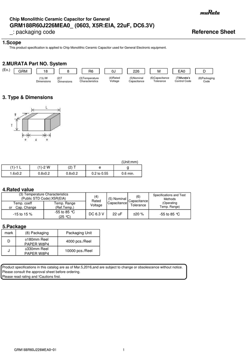
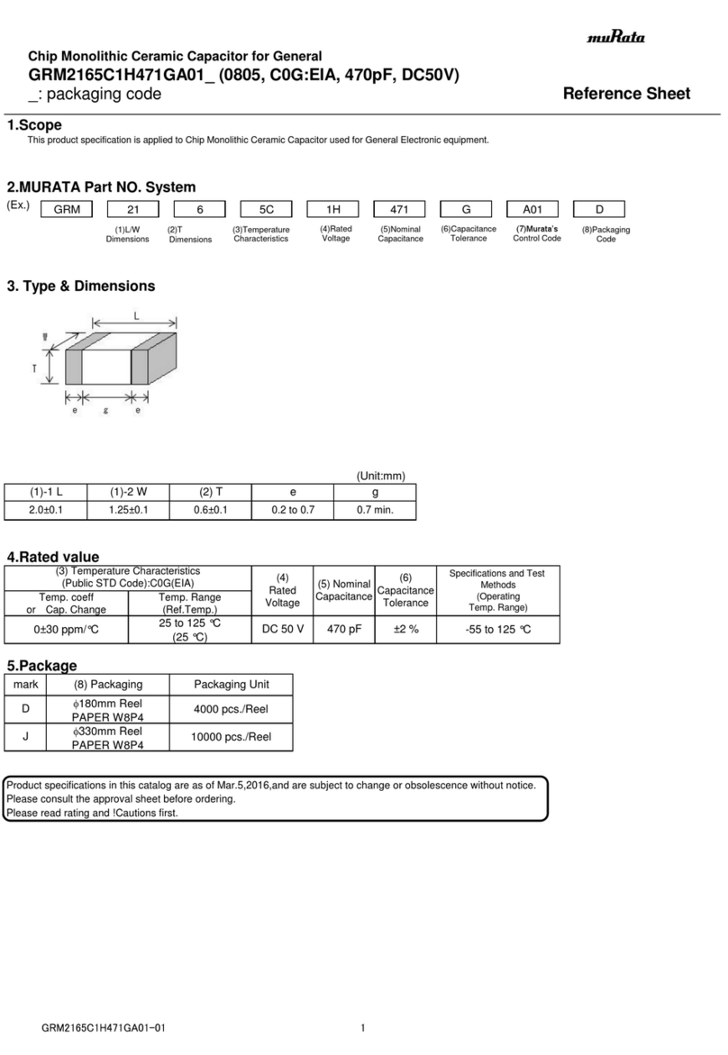
Murata GRM2165C1H471GA01 Series Reference sheet

Murata

Murata GRM2165C1H471GA01 Series Reference sheet

Mennekes AMAXX Installation & operating instructions

Mennekes

Mennekes AMAXX Installation & operating instructions

Pelican 9455 user manual

Pelican

Pelican 9455 user manual

Murata GRM188R60J226MEA0 Series Reference sheet

Murata

Murata GRM188R60J226MEA0 Series Reference sheet

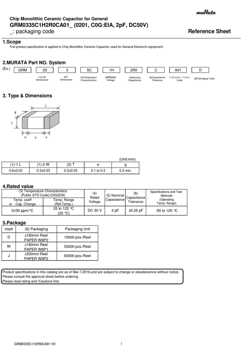
Murata GRM0335C1H2R0CA01 Series Reference sheet

Murata

Murata GRM0335C1H2R0CA01 Series Reference sheet

YASKAWA SI-EL3 installation manual

YASKAWA

YASKAWA SI-EL3 installation manual

Murata GJM0335C1E130GB01 Series Reference sheet

Murata

Murata GJM0335C1E130GB01 Series Reference sheet

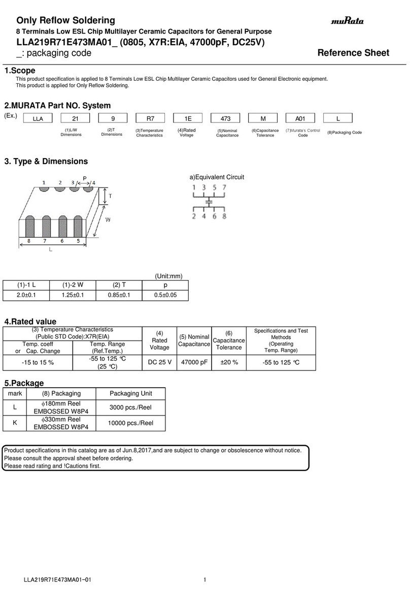
Murata LLA219R71E473MA01 Series Reference sheet

Murata

Murata LLA219R71E473MA01 Series Reference sheet

Murata GQM2195C2A130GB01 Series Reference sheet

Murata

Murata GQM2195C2A130GB01 Series Reference sheet

LEAB CDR 200/40 user manual

LEAB

LEAB CDR 200/40 user manual

Siemens 3VA9588-0VM10 operating instructions

Siemens

Siemens 3VA9588-0VM10 operating instructions

Murata GJM0225C1E5R9CB01 Series Reference sheet

Murata

Murata GJM0225C1E5R9CB01 Series Reference sheet

Ormazabal velatia cpg.1 General instructions

Ormazabal

Ormazabal velatia cpg.1 General instructions

Murata GCJ216R71E103KA01 Series Reference sheet

Murata

Murata GCJ216R71E103KA01 Series Reference sheet

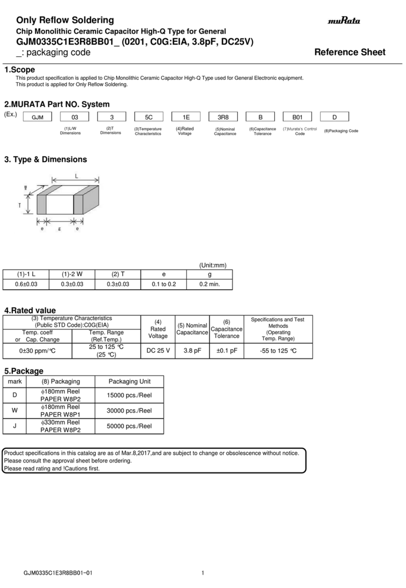
Murata GJM0335C1E3R8BB01 Series Reference sheet

Murata

Murata GJM0335C1E3R8BB01 Series Reference sheet

Eaton CHFPCS manual

Eaton

Eaton CHFPCS manual

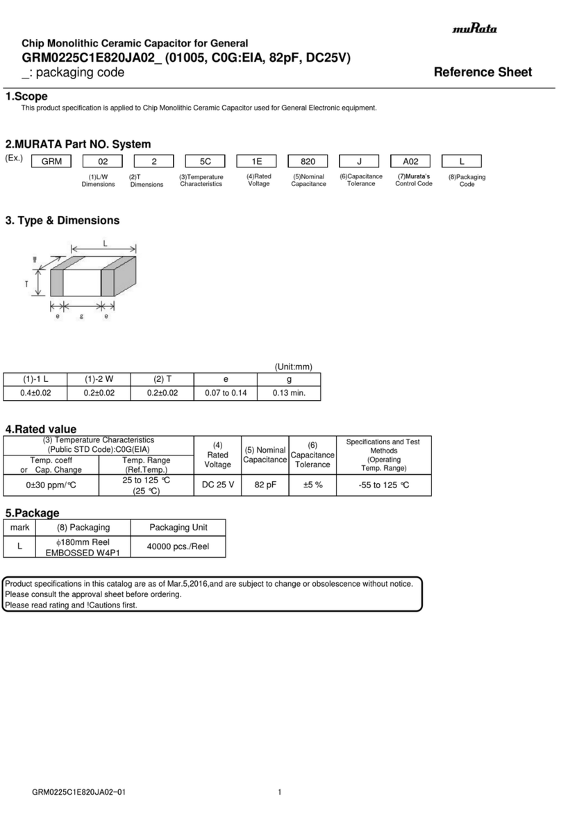
Murata GRM0225C1E820JA02 Series Reference sheet

Murata

Murata GRM0225C1E820JA02 Series Reference sheet

manuals.online logo
manuals.online logoBrands
  • About & Mission
  • Contact us
  • Privacy Policy
  • Terms and Conditions

Copyright 2025 Manuals.Online. All Rights Reserved.