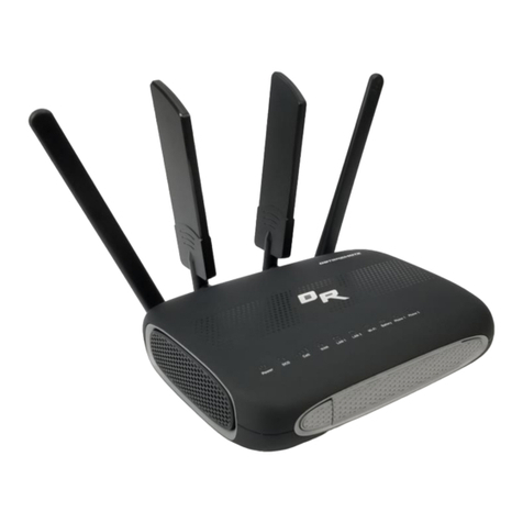
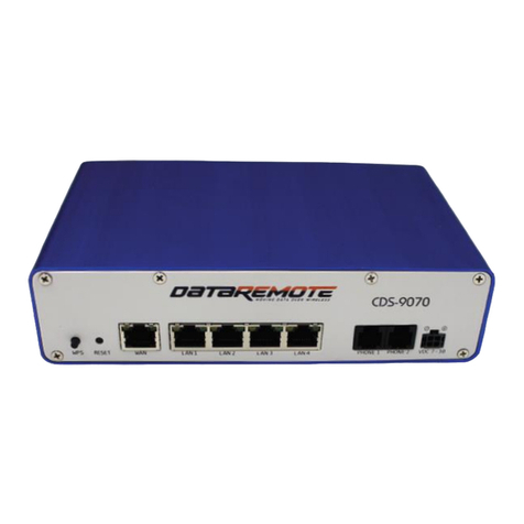
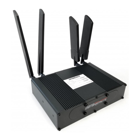
DataRemote Pots In a Box CDS-9090 User manual

WHAT CAN YOUR
NEW DEVICE DO?
Virtually every application
that requires a copper hard-line
can now be replaced with one device!
USER MANUAL
CDS-9090
Dual Band Wi-Fi Router
LTE VoIP
Revision No. 004 April 2020

ONE DEVICE
TO REPLACE ALL YOUR LANDLINES
DATAREMOTE
DEVICE MANAGER
PSTN
LTE/WAN PBX
Meter Reading
Voice
Fire Alarms
Burglar Alarms
Elevator
Fax
Emergency Call Box
Point of Sale
Security Gate / Door Access Box
Modem Data
DATA
Cell 1 Main Cell 1 Div
Reset
SIM 1 SIM 2
1 2 3 4 5 6 7 8
WiFi WiFi
Console
LAN 1 LAN 3
LAN 2 LAN 4 SFP VDC 7-16 ON/OFF
CDS-9090
WAN
TheDataRemote CDS-9090 wireless router with VoIP is a stand-alone device which facilitates clear
and reliable voice quality over the Internet; it is fully compatible with Session Initiation Protocol (SIP)
industry standards andcan integrate with many other SIP devices and software on the market.
HARDWARE INSTALLATION
FOLLOW ALL THE STEPS AS SHOWN ON THE PICTURES AND THE DESCRIPTION, IF
YOU HAVE ANY QUESTIONS RELATED TO THE HARDWARE INSTALLATION, PLEASE
CONTACT THE SUPPORT NUMBER PROVIDED ON YOUR DEVICE’S BOX.
Page 2
DataRemote offers enterprise-grade solutions for traditional landline replacement.
Our suite of products converts all your existing legacy landlines to next generation
service via VoIP and the LTE cellular network whether it be voice, Fax lines, burglar,
fire alarms, elevators, ATM's, emergency call boxes, point of sale systems and more.
Revision No. 004 April 2020

TABLE OF CONTENTS
Page 3
What comes in the Box
What do you need to know before installing your device
LED Lights Indicators
What is on the front of your device
Basic Installation (Step by Step)
Service Technician Installation
Overview
Scope of Work
Materials List
Pre-Work
Phase 1 – DataRemote CDS-9090 device assembly/Pre-Test + Fire Panel location
Phase 2 - Installation Tasks – Locate existing POTS lines
Phase 3 - Cut-over Fire Panel Lines to new ATA device
Phase 4 - Testing Fire Alarm Communication over DataRemote's CDS-9090 device.
Phase 5 - Testing Fax Lines.
Phase 6 - Testing Analog Data Lines.
Post Installation Tasks
Deliverables
Advanced Programming Information
Statements and Disclaimers
Revision No. 004 April 2020

WHAT COMES IN THE BOX
DATAREMOTE CDS-9090 DEVICE LTE AND WiFi ANTENNAS
AC POWER ADAPTER ETHERNET AND PHONE (RJ11) CABLES
SET OF MOUNTING
HARDWARE X1 MOUNTING BRACKET
Page 4
Revision No. 004 April 2020

Before you can connect your DataRemote CDS-9090 device to the Internet and use it, you must
have access to high-speed Internet. A high-speed Internet connection can be accessed through
DSL, LTE wireless network, cable modem, Wi-Fi access point, or a leased line.
Make sure you are connecting your new DataRemote CDS-9090 device near a power source and
away from extreme heat / humid sources.
As this device uses LTE, please make sure that wherever you are installing the device, there is good
cell reception. The device should also be installed in a location which is easily accessible.
WHAT DO YOU NEED TO KNOW
BEFORE INSTALLING YOUR DEVICE
IMPORTANT:Please refrain from putting furniture or otherobstaclesin front of the device
as it might influence the signal, thus degrading the quality of service.
LED LIGHTS INDICATORS
NOTE: Before you use your device, please get acquainted with the LED indicators and
connectors first.
REAR PANEL
LED STATUS
LED STATUS EXPLANATION
POWER On (GREEN)
On blinking (GREEN)
OFF
On (RED)
The router is powered on (external power) and running normally.
The router is powered on (Internal Power - BAT) and running normally.
The router is powered off.
System Fault (Software or Hardware)
Page 5
Revision No. 004 April 2020

LED STATUS EXPLANATION
BATTERY(BAT)
FXS ports
WiFi Client
WiFi AP
WAN ETH
Cell 1/2
RSSI
CELL DCD
SIM
On (GREEN)
On blinking (GREEN)
RED
On (GREEN)
OFF
On (GREEN)
OFF
On (GREEN)
On blinking (GREEN)
OFF
On (GREEN)
On blinking (GREEN)
OFF
On (GREEN)
On blinking (GREEN)
OFF
On (GREEN)
On blinking (GREEN)
OFF
On (GREEN)
On blinking (GREEN)
On (RED)
On (GREEN)
On blinking (GREEN)
Off
On (GREEN)
Battery charged
Battery charging
Battery low or not connected
Registered
Not registered
Active for key registration
Non active for key registration
Wireless client connected
Wireless traffic (data)
The wireless client is powered off or not connected
Wireless AP ready
Wireless traffic (data)
The wireless AP is powered off
Connected (registered)
Connected (data)
Disconnected
Connected (registered)
Connected (data)
Disconnected
Strong
Medium
Weak
LTE
3G
No service
SIM accepted
LED LIGHTS
INDICATORS (continued)
Page 6
Revision No. 004 April 2020

WHAT IS ON THE
FRONT OF YOUR DEVICE?
Cellular antennas connectors Wi-Fi antennas connectors
Front panels
LED status
SIM cards slots Eight (8)
FXS phone line
outlets
Four (4)
Ethernet
outlets
WAN
Wide Area Network
(Internet)
connector outlet
AC power
cord connector
outlet
ON/OFF
button
SFP outlet
(High speed
data transfer)
REAR PANEL INTERFACE DESCRIPTION
AC power cord connector outlet DC
Wide Area Network (Internet) connector outlet
Four (4) Ethernet outlets
WAN
LAN1/2/3/4
Connector for a power adapter.
Connector for accessing the Internet.
Connectors for local networked devices.
BASIC INSTALLATION
IMPORTANT! Before starting to configure the router, please
connect your device as shown in these "step by step" directions. If
you have any questions regarding installation, please contact the
Support number provided on your device’s Box.
Page 7
Revision No. 004 April 2020

STEP 1
The SIM card slots are located on the left bottom corner of your device. Insert the
SIM card inside the slot marked “SIM 1”. Make sure is inserted all the way into the
slot. You will feel a spring lock the SIM card into place.
BASIC INSTALLATION (Continued)
Page 8
Revision No. 004 April 2020
Then connect one end of the power cord to the power port of your device, then
connect the other end to an electric outlet.

STEP 2
Connect the WAN port of your device to a modem, switch, router or Internet with
an Ethernet cable (RJ-45).
DISCLAIMER: This is just a representation of a modem. Modem models and appearance may vary
depending on your Internet provider.
STEP 3
Connect to one of the four LAN ports on your device with an Ethernet cable
(RJ-45) to your equipment or computer that needs to receive an Internet
connection from the DataRemote CDS-9090 device. Your device allows you to
connect up to four (4) devices.
Page 9
Revision No. 004 April 2020

STEP 5
Connect the antennas to their respective ports (WiFi and CELL)
Page 10
Revision No. 004 April 2020
STEP 4
Connect the RJ-11 (Phone line) from your phone or equipment requiring a phone
line to the DataRemote CDS-9090 device’s FXS port.
Do not connect an active RJ-11 with voltage directly from the
wall into the DataRemote device’s RJ-11 ports, this will
damage the device permanently. Each DataRemote device’s
RJ-11 FXS port is an active port supplying voltage. The FXS
port is only to be connected to an FXO analog phone or
another FXO device.
WARNING!

STEP 5 (continued)
STEP 6
Check the Power, WAN and LAN LEDs lights to make sure you are connected
properly.
Your device should look like this when connected to a phone line, WAN and one
LAN/computer device. Make sure the antennas do not touch each other.
Page 11
Revision No. 004 April 2020
Make sure the antennas do not
touch each other, this will
cause the connection to be
degraded.
WARNING!

STEP 7
Finally, with the help of a clip or a pen, turn 'ON' the ON/OFF button to turn on
your device.
SERVICE TECHNICIAN
INSTALLATION
Overview of the DataRemote CDS-9090 device.
The DataRemote CDS-9090 device is part of DataRemote's POTS (Plain Old Telephone
Service) In A BOX product line. It is an Analog Telephone Adapter (ATA) with battery backup that
uses the Internet and the LTE Cellular Data Network to provide high levels of reliable cellular
connectivity to directly replace wire-line POTS lines, including the capability for transmission of
voice, FAX, alarm, analog data, ring-down and emergency lines with full access to E-911.
SCOPE OF WORK.
The scope of work to be completed on-site can be summarized to consist of the following:
Locate existing devices (ie: Fire Panel(s), Call Boxes, Faxes, Voice lines).
Using a cable toner, locate demarc for existing POTS lines currently serving devices.
Unpack, assemble then test DataRemote CDS-9090 device unit in "Standalone" Mode with
power cable connected.
Mount DataRemote device and test FXS 1-8 (if applicable) phone jacks by calling in/out
using a telephone test set or a simple single line telephone and cell phone prior to
connecting any device/appliance.
Page 12
Revision No. 004 April 2020

SCOPE OF WORK. (Continued)
MATERIALS LIST.
PROVIDED BY DATAREMOTE:
Basic Package Contains (Refer to “What comes in the Box” section)
One (1) DataRemote CDS-9090 device.
One (1) 100-240VAC, 50/60Hz, 1.0A to 15.0VDC, 2.0A power adapter.
One (1) AC power cord.
One (1) Ethernet cable RJ-45.
Two (2) Phone cable RJ11.
Two (2) LTE antennas (SMA-M connectors)
Two (2) Wi-Fi antennas (SMA-M-RP connectors)
One (1) Mounting bracket.
TOOLS LIST FOR TECH:
Sufficient quantity of dual RJ-45 port surface mount boxes (aka biscuit jack)
Sufficient quantity of RJ11 or RJ-45 keystone plugs
CAT5E cable – minimum 150'
Power strip (this may not be used, it is in case there are not enough outlets in the room)
Zip Ties / Velcro for wire management
Extra RJ-11 cable and RJ-11 male adapters, in the event additional or longer runs are
required.
Page 13
Mount the biscuit (RJ-11 Surface mount) jacks close to the DataRemote CDS-9090 device
that will connect with the remote device.
Connect existing devices to newly installed RJ11 biscuit jacks.
Ensure no "Foreign Voltage" is present by measuring the voltage at the tip and ring
terminals on the new biscuit jacks connected to the devices. Voltage should read: “zero”
volts DC (direct current)
IMPORTANT! IF foreign voltage is present, locate and disable it. IF no foreign
voltage is present, proceed to next step
Connect the DataRemote CDS-9090 device FXS 1-8 (if applicable) jacks to existing devices.
If Call Box or Voice line, test by making inbound/outbound calls.
If Call Box also test 'Gate/Door Entry" tone (DTMF / 'Press 9") and programming calls
inbound to the device. Request client or call vendor technical support to facilitate
programming test calls as needed.
If Fire Alarm Panel, test that Fire Alarm Panels primary & secondary lines accordingly, calling
out through the DataRemote CDS-9090 device. If RJ-31 style jack is used, verify that tip/ring
connections are on pins 4 & 5 of jack.
If FAX, test by sending/receiving FAX using customer equipment.
Revision No. 004 April 2020

TOOLS LIST FOR TECH (continued)
Flashlight
Cat5 patch cables of varying lengths
Cordless drill/driver with bits to install light-duty ATA mounting bracket to wallboard
All termination tools and line/tone testers
NOTE: Photo of Cable Tester results will be required in deliverables
All hand tools required to make Cat5 cable runs (glow-stick, wire tape, etc.)
Butt Set (or analog test telephone if Butt Set doesn't have an RJ11 plug/jack interface)
Label maker (to label biscuit jacks)
Digital camera with 3.0 mega pixels or higher photo resolution
6" torpedo level
Voltmeter
Please review this steps before starting and ensure you bring a printed copy of this guide and
installation checklist to the site, to use it as a reference during the installation.
PREP-INSTALLATION TASKS.
On-site Arrival and Initial Equipment Testing:
1. Upon arrival, call your respective Program Manager on the check-in line to confirm that you are
on-site and be prepared to supply the store number/location ID & city/ST listed on your Work
Order
2. Ask for the Manager On Duty (MOD), and introduce yourself with the purpose of your visit as the
installer for the DataRemote CDS-9090 device.
a. Please report any store access issue to your Project Manager immediately.
3. The DataRemote device was shipped to the site in advance of your dispatch; please obtain this
package from the Manager.
a. IMPORTANT: Please open the package in front of MOD and inspect for a complete kit
per the previous page's material's list; especially if package was already opened when
it was given to you
b. Report any missing equipment immediately to Project Manager.
4. IMPORTANT: ANY directives from on-site store personnel deviating from the norm or outside
the scope of this guide must be relayed to the PM immediately. If you encounter a problem in
the field which requires escalation, please contact the PM immediately (bottom line, contact
PM for approval prior to accepting and acting upon any direction from store personnel
on-site).
IMPORTANT! TECHNICIAN MUST FOLLOW THIS MANUAL EXACTLY, AS EACH PHASE & STEP
IS DESIGNED TO ENSURE PROPER MIGRATION. ANY DEVIATION MUST ABSOLUTELY BE APPROVED
BY YOUR RESPECTIVE EMPLOYER ONLY!!
Page 14
Revision No. 004 April 2020

ASSEMBLE THE DATAREMOTE CDS-9090 DEVICE TO PRE-TEST:
1. Remove the CDS-9090 device and affix the antenna accordingly:
a. WARNING! THE WiFi ANTENNAS CONNECTORS ARE DIFFERENT FROM THE
LTE ANTENNAS CONNECTORS, SO FORCIBLY CONNECTING THEM INCORRECTLY
WILL DAMAGE THE ANTENNAS AND POSSIBLY THE CDS-9090 DEVICE
APPLIANCE COAXIAL PORT AS WELL.
b. LTE Antennas – Male Center Pin WiFi Antennas – Female Center Hole
DATAREMOTE CDS-9090 DEVICE ASSEMBLY
/PRE-TEST + FIRE PANEL LOCATION.
PHASE 1
*Be aware of the difference of LTE and WiFi Antennas*
Page 15
LTE
WiFi
LTE
WiFi
Revision No. 004 April 2020

Cellular antennas connectors Wi-Fi antennas connectors
c. LTE antennas connect to outer two (2) coaxial connectors on the DataRemote
CDS-9090 device and WiFi antennas connect to the two (2) inner coaxial connectors:
2. Slide power switch, located on the lower front right side of the CDS-9090 device, to "ON" position
to turn unit on running off its battery and temporarily plug the device into AC power. Ensure the
power block and power cable are supported to prevent damage to the molex power plug.
3. Once the DataRemote CDS-9090 device is positioned to achieve the best signal strength
possible: high on the wall with antennas facing up, use your eye and torpedo level to install the
DataRemote CDS-9090 device mounting bracket in the selected location. Dress and secure the
DataRemote CDS-9090 device's AC adapter and power cable's path neatly, then secure the
DataRemote CDS-9090 device unit to the bracket with the included screws. If there are questions
about the unit's placement, please contact Installation Support.
4. Plug the device into its permanent AC power; verify correct LED lights on the DataRemote
CDS-9090 device.
WAN (Wired Broadband) – WAN link light is on
LTE (SIM, DCD, SVC) – Lights all light for each SIM in the device is on, cell strength LEDs (1 -3, 3 being
the strongest) are on
WiFi – AP LED on 2.4G or 5G respectively is on
Line Registration Verification via LEDs
FXS port – LED light is on for each line enabled and registered
PHASE 1 (continued)
Page 16
DATAREMOTE CDS-9090 DEVICE ASSEMBLY
/PRE-TEST + FIRE PANEL LOCATION.
Revision No. 004 April 2020
WAN CONNECTIVITY VERIFICATION VIA LEDs

TESTING FIRE PANEL.
1. Phone FXS 1-8 indicators should be either solid green (On-Hook) or flashing green
(Off-Hook/Busy). Call Installation Support if LED indicators for the FXS ports are not lit. Once the
lights above have been verified, use a butt-set (or an analog test phone if your model butt-set doesn't
have an RJ-11 modular connection) to place a test call from the phone 1 jack to your cell phone (if line
one is a voice line.)
2. IMPORTANT: You MUST complete the call by answering it; otherwise the device won't
register the test call event in the server logs, which is used for install validation.
3. NOTE: If there are any issues other than a completed call and calling number
identification/verification such as call didn't go through or any other condition, STOP and call
Installation Support to report the issue and work to resolve before proceeding. Record the
calling phone numeber in the checklist for this site as phone 1's (primary) new ATA number.
Repeat steps 2 - 5 accordingly by performing the steps again using the phone 2-8 line ports of
the DataRemote CDS-9090 device (If the lines are voice lines.)
TESTING VOICE LINE.
.
NOTE: ANY VARIATIONS FROM THE ABOVE, SEE THE TROUBLESHOOTING GUIDE attached
separately in your Work Order and/or call your respective Installation Support Line.
1. Locate the Fire Alarm Panel. Have the Manager escort you to the room/area where the active
Fire Panel is located, if not already visible refer to your Installer Representative Manual for a sample
picture of typical Fire Alarm Panels.
-A good indication that you've identified the correct Fire Alarm Panel is when you find the
two(2) existing POTS lines that are associated with the Fire Alarm Panel. The two (2) existing POTS
lines can appear in varied termination options and locations, such as:
a. Two(2) surface-mount jacks located just outside of the Fire Panel, generally
RJ-31 style
b. In a 4x4 electrical box just off to the side of the fire panel.
c. Jacks may be inside the Fire Alarm Panel on Motherboard and/or a dialer
module.
IMPORTANT: DO NOT TOUCH these existing surface mount jacks or their cabling at this time!
.
Page 17
Revision No. 004 April 2020

-Take a "BEFORE" picture of the panel and any status indicators/displayed messages
appearing to represent the condition of the panel upon arrival!
CAUTION: DO NOT DISCONNECT ANY EXISTING PHONE LINES UNTIL INSTRUCTED TO DO SO LATER IN
THIS DOCUMENT. TO DO SO EARLIER, MAY RISK A POSSIBLE DISPATCH FROM THE RESPECTIVE ALARM
COMPANY.
Installation Tasks – Locate Existing POTS Lines
PHASE 2
WARNING! DO NOT TOUCH THE EXISTING RJ-31 POTS JACKS NEAR FIRE PANEL UNLESS
INSTRUCTED TO DO SO
Once the Fire Panel is located, you will need to connect the DataRemote CDS-9090 device's phone
1-8 ports respectively with the Fire Alarm Panel's primary & secondary phone line ports preferably
utilizing the existing cabling already connecting those ports to their current POTS lines.
As stated earlier in Step 1, when trying to find the Fire Alarm Panel, that cabling is typically
terminated near the Fire Panel via some method before running inside the panel to connect to it. A
common method uses two (2) surface mount jacks, but you may see other methods as well.
ID the termination points of those two(2) POTS lines serving the Fire Alarm Panel at the telco
Closet/demarc. To do so, try one or more of the following:
TESTING FIRE PANEL. (Continued)
Look for the two (2) telephone number's (TN) if ID's and labeled at the Fire Panel and record
them in your installation checklist and then look for labels with those TN's at the Telco
Room/Demarc.
Be sure to also note which TN may be labeled primary or secondary.
Tone-trace the existing cabling:
Temporarily unplug the cable from the Fire Alarm Panel leading into one of the RJ-31x
surface mount jacks.
Page 18
Revision No. 004 April 2020

Plug tone-generator into the surface mount jack to tone-out the cabling back towards the
Demarc to discover its location. Repeat for other RJ-31x jack/cable too if needed.
Restore connection to RJ-31 jack(s) if removed to conduct tone-test.
Installation Tasks – Locate Existing POTS Lines
PHASE 2 (continued)
Cut-over Fire Alarm Panel lines to new CDS-9090 device.
PHASE 3
CAUTION: ONLY PROCEED IF STEPS 1 AND 2 ARE COMPLETE & WITHOUT ANY OPEN ISSUES.
Once those POTS Line terminations are found in the telco closet demarc/SIN, their cable-runs to
the Fire Alarm Panel need to be isolated from their telco POTS lines and redirected to the
DataRemote CDS-9090 device’s phone ports using included 5' long phone cords. The method of
termination of those lines coming back from the Fire Alarm Panel will dictate the next steps taken to
cut them over to DataRemote CDS-9090 device.
1. If the cable runs coming from the Fire Panel terminate in the Telco closet demarc/SIN to an RJ-11
or RJ-45 patch-panel or surface-mount (SMT) jack:
a. Determine which jack is associated to the primary or secondary line from Fire Alarm
Panel and mark them respectively with new device’s telephone numers as noted
in your checklist during Step 1 tasks for 9090's phone 1-8 ports respectively.
b. Remove what's plugged into the Primarily marked jack now and plug one end of a
phone cord included in the kit into that jack and the other end into Phone jack of the
DataRemote CDS-9090 device respective line for Fire Alarm – Primary Dialer connection.
NOTE: Mark this phone 1 port's phone cord with a "1" or "P" to reflect it connects to the
CDS-9090 pevice's phone alarm port.
c. Repeat with other included phone cord for secondary marked jack into phone 2 jack of
the DataRemote CDS-9090 device for Fire Alarm – secondary dialer connection
Page 19
Revision No. 004 April 2020

Cut-over Fire Panel Lines to New CDS-9090 device.
PHASE 3 (continued)
NOTE: Leave it unmarked or place a "2" or an "S" on its phone cord.
d. If cable runs coming from the Fire Panel terminate in the Telco closet demarc/SIN to
a 66 or 110 block, check the following:
- Determine which jack is associated with the Primary or Secondary line of Fire Panel and
mark them accordingly it if not already apparent/visible.
- Isolate the Telco side connection from those two (2) pairs (i.e. lift bridging clips on
66-Block) Punch-down the two pairs of the new cable run to a dual SMT jack or two (2)
Single-port SMT jacks (a.k.a. biscuit jacks)
- Determine and mark/label each SMT jack cover with its new device Telephone number
plus some primary or secondary suffix - i.e: 678.555.1234 678.555.2468 FIRE PNL-Prim
FIRE PNL-Sec
2. Mount the SMT Jack(s) somewhat near to the DataRemote CDS-9090 device depending on 5' long
phone cord's reach and distance between 66-Blk & SMT box(es)
3. Using your cable tester, test both SMT jack terminations and take PHOTO of test results to add to
deliverables (REQUIRED).
4. Using included phone cords with RJ-11 terminations, connect FXS alarm ports from CDS-9090
device to the “FIRE-Primary & FIRE-Secondary” SMT box respectively
5. Mark Cables:
- Mark the DataRemote CDS-9090 device alarm line 1 port's phone cord with a "1" or "P"
to reflect it connects to the DataRemote CDS-9090 device's alarm line 1 port.
- Mark the DataRemote CDS-9090 device's alarm 2 port's phone cord with a "2" or "S" to
reflect it connects to the DataRemote CDS-9090 device's alarm line 2 port.
Testing Fire Alarm communication over
DataRemote's CDS-9090 device.
PHASE 4
The DataRemote CDS-9090 device will be set in auto alarm mode. Meaning it will detect what type
of supported protocol the panel communicates in (Contact-ID, SIA, Pulse...Etc)
NOTE: do not plug in a butt set to the cds-9090 device and make a test call on any of the alarm
lines as this will deactivate the auto detect mode.
The first call will fail, if calls continue to fail contact installation support.
Page 20
Revision No. 004 April 2020
Other manuals for Pots In a Box CDS-9090
2
This manual suits for next models
1
Table of contents
Other DataRemote Wireless Router manuals
