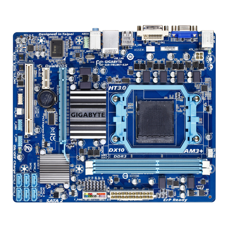
Datatech Enterprises Mini 80386SX User manual

o
Mini 803863X
20MHz Mainboard
User’s Manual

PPM-2030C
Mini 803863X
20 Hz Mainboard
User’s Manual
-
_
Edition 1.01
©1990 Datatech Enterprises Co., Ltd.
The PPM-20300. this manual and all illustrations in it are
copyrighted with all rights reserved. Under the copyright laws the
PPM-20300. this manual and illustrations may not be copied
without the written consent of Datatech EnterprisesCo., Ltd.

Warning
Reconfiguring
NEVER reconfigure the board while the power is
ON.
If you wish to reconfigure the board at any time,
make sure that the power is tumed OFF before
changing any hardware settings such as DlP
switches or jumpers.
N019
-When you see an error message on the screen
after turning the power on, leave the system
switched on for one to two hours to charge the
battery. You can then enter the system con-
figuration.
-Later, leave your system switched on for 10 to
15 hours to completely charge the battery.
-It you leave the system switched off for more
than one month, repeat the steps above.
-It you are using an onboard battery, be sure
pins BATl' and INT (2 and 3) of jumper W13
are shorted when you install your system.
Otherwise, you will have to set up your con-
figuration whenever you turn on your computer.
Checklist
Your PPM-20300 mainboard package contains the
following:
-One PPM-20300 mainboard
-One user’s manual
-One BIOS system setup manual
-One EMS driver diskette
Theifollowing does not apply to any country where such
provrswns are inconsistentwith local law:
Datatechmakes no warrantieswith respect to this documentation
eitherexpress or implied and provides it “as is". This includes but
is not limited to any implied warranties of merchantability and
fitness for aparticular purpose.,Theinformation in this document
is subject to change without notice. Datatech assumes no
responsibility for any errors that may appear in this document.
All brand names are registered trademarks of their respective
companies.

Contents
_
Introduction ............ ..................... 1)
Features ........................... 2
Board Layout ................................ 3
Dimensions of PPM-2030C .................4
Board Setup ................................. 5
RAM Installation ....................... 5
Jumpers W1 -W6 ....................... 6
512KB Total System Memory .................. 8
640KB Total System Memory .................. 9
1MB Total System Memory ...................10
1.5MB Total System Memory ..................11
2MB Total System Memory ...................12
3MB TotalSystem Memory ...................13
4MB Total System Memory ...................14
5MB Total System Memory ...................15
ROM Installation ..................... 16
Connectors ........................ 17 )
Functions of Panel Indicators and Switches ..........17
CPU Frequency Indicator ....................17
Keylock &Power LED .....................18
Hardware Switch ........................18
Speaker ............................. 19
Turbo LED ........................... 19
Reset .............................. 19
Display AdapterSettings .................. 20
Power Good and Power Fail Detect ............ 20
803868X CPU ...-. ................... 21
Address Pipeline ........................21
Math Coprocessor Installation ............... 22
Connectionto Power Supply ............... 24
Choosing aPower Supply ...................25
Battery Connector ..................... 26
Keyboard Connector .................... 26
4—:-
Software .................................. 27
Shadow RAM Enable ....................27
EMS Driver Setup ..................... 28
Operation .................................. 30
Entering 20MHz Turbo Mode ............... 30
Software Turbo Switch ................... 30
Hardware Turbo Switch .................. 30
Factory Default Settings .................. 31
Technical Information ........... ............. 32
Microprocessor ...................... 32
Protected Virtual Address Mode .............. 32
Real Address Mode .................... 33
System Timers ................... '. .. . 33
System Interrupts ..................... 34
ROM Subsystem ...................... 35
RAM Subsystem ...................... 35
Direct Memory Access ................... 36
DMA Channel ....................... 36
I/O Channel Slots ..................... 38
Math Coprocessor Control ................. 39
Appendix A................. ....... ......... 40
Quick Reference for Jumper Settings ........... 41

Introduction
The PPM-2030C mainboard is compatible with the
PC/AT. This means that virtually all the software avail—
able for the PC/AT can also be run on asystem you
build around the PPM—2030C mainboard.
The PPM-2030C incorporates the Intel 80386SX
which is a32-bit CPU with a16-bit external data bus
and a24-bit external address bus. The 80386SXCPU
brings the high-performance software of the lntel
80386 architecture to midrange systems. It provides
the performance benefits of a32-bit programming
architecture and the cost savings associated with
16-bit hardware systems.
Moreover, the 803868X microprocessor is 100% ob-
ject-code compatible with the 386, 286, and 8086
microprocessors. Therefore, PPM-2030C CPU-
based systems optimize both for performance and
cost. The PPM-2030C can access the world's largest
existing microcomputer software base, including the
growing collection of 32-bit software.
For these reasons, the PPM-2030C mainboard is the
ideal choice for aperson seeking affordable ’386
power.
The clear, well-illustrated instructions in this manual
ensure that even if you are anewcomer to the com-
pUter world, you will have your system installed and
running with aminimum of effort.

Features Board~ Lazout
The PPM-20300 includes the following features:
-|nte| 803868X.20 microprocessor __ 32-bit Below is alayout 0f the PPM-2030C ShOWing the
CPU with a16-bit external data bus and a24- y)Jumpers and some of the connectors. The figure on
bit external address bus ‘the next page gives the dimensions of the board.
-lntel 80387SX—2O coprocessors optional
-Use of C&T’s CS8221 PC/AT-compatible chip ‘‘
w7
set. _W1—-wa ws—i ‘l
w2_wa_ mm J7—
-Switchable between 10MH2 Normal mode and
20MHz Turbo mode by either asoftware switch
or ahardware switch
'Onboard battery backup for CMOS configura-
tion table and real-time clock
-RAM subsystem of 512KB, 640KB, 1MB,
1.5MB, 2MB, 3MB, 4MB and 5MB
-Eight expansion slots —Six 16 bit slots and
two 8bit slots
-Sixteen—level interrupt )J:ahargable
iler
-Seven-channel DMAfor disk and special l/O I
-64KB legal DTK BIOS (ADL certified) :' ___-_ __ll __-:, 05%;?"
developed by Datatech Enterprises Co., Ltd. {
-Four-layermainboard “—m 'l ‘l E—w12 '3
0o
-LlM 4.0 EMS support _i‘
we mw“ w”
-Shadow RAM support J2—-.‘J3 PM,
-Choice of either 44256 DIP or 256K/1M SIMM i“_
°° ° ‘g‘fl -J‘ Si‘E’J’i"
DRAM modules with 80ns i
-Page/Interleaved DRAM access method sup—
port
-Power fail detect circuit Figure: The Location of Jumpers and Connectors
-Address pipeline support

Dimensions of PPM-20300
All the dimensions are in millimeter(s).
Board Setup
In this section references will be made to jumper
settings used to configure the variousfunctionsof the
PPM-20300 mainboard. Refer to the Board Layout
section for locations of all jumpers.
RAM Installation
Jumpers W1- W6 are used to set the RAM size you
want on the mainboard. The DIP and SIMM DRAM
banks can containfrom 512KB, 640KB, 1MB, 1.5MB,
2MB, 3MB, 4MB to 5MB by means of setting jumpers
W1 -W6. Reterto the illustration below torthe location
of jumpers W1 —W6 and the RAM banks.
JIllltlllllllllllllllllltllllll"
$1".ng r. Bantu/2
lIEEI EEEIJ DEED
lBank 0II Bank 1I
WIHHIlullIIHIIIIIIHHIIIIIVJ
wlllllllllllllllllllll _IIIII a4 ’~Bank 1/3
111111111111111
111111111111111
111
111 1111
TI11111HH1111111 1111
1111111 111111 111
11 111
111
I
l
I
IIIIIH lmm m
m In In-
___W
___- -I
-”E__
Figure: RAM Banks &Jumpers for Bank
Selection

The following figures show the configuration for total
onboard system memory.
Description
W1 -W6
Settings
Using one bank or two banks (banks 0&1) with
either DlP or SlMM DRAMs as onboard memory —> -
Using three or tour banks of DIP (banks 0, 1) and
SIMM (banks 2, 3) DRAMs as onboard memory
SysterTnolllflmorY Bank 0BagslM 21:; 2Bank a gill; lntgfiggvo R°f°'°"°°
512K 256K OK OK OK 1Disable Page 8
640K 256K 64K 0K 0K 1Disable Page 9
0Enable
1MB 256K 256K 0K 0K 1Enable Page 10
1Disable
1.5MB 256K 256K 256K OK 1Disable Page 11
0Enable
2MB 256K 256K 256K 256K 1Enable Page 12
1Disable
2MB 1M 0K 0K 0K 1Disable Page 12
3MB 256K 256K 1M 0K 1Disable Page 13
0 Enable
4MB 1M 1M 0K 0K 1Enable page 14
1Disable
0Enable
5MB 256K 256K 1M 1M 1Enable Page 15
1Disable
RAM access time is 80ns
Note: To function normally, your system has to be in
Normal Mode but not Turbo mode, if your system is
operating in both zero wait-state and disabled page
interleave mode.
Million Instruction Per secondTest
The Million Instruction Per Second (MIPS) perfor-
mance test —for page-interleave/zero—wait is in 2.45
and for Turbo mode/one—wait is 2.23.
<~e.—
.z,
.w,
'
Chip Insertion
Rememberthat when inserting chips, you must make
sure the notched or dotted end of the chip is lined up
wrth the notched end of the socket. Gently push the
chip into the socket, and be careful not to bend the
pins.
Jumper
Ajumper is akind of switch which uses aplastic cap
with ametal interior to connect (short) two pins. It a
jumper needs to be left open, you should save the cap
for future use by covering one pin only of the jumper.
This has no effect on the function of the board while it
keeps the cap handy. The illustration below shows the
side and top views of athree-pinjumper in which pins
two and three are shorted.
Side View Top View
.L
To select the proper jumper setting for the RAM size
that you want, refer to the figures on the following
pages.

512KB Total Onboard System Memory
Bank 0=41256 RAM Module x2pieces
°IIIIIIIII
IIIIIII
lllllll
IlIIIIl
or Bank 0=(44256 X4+41256 X2)
Jumpers W1 -W61
11
You may use either bank as bank 0.
1i» 1
640KB Total Onboard System Memory
Bank 0=41256 FlAM Module x2pieces
__°IIIIIIIII
30
L‘UIIIIIIIIIIIIIIIIIIIIIIIIIIIIIIG'J
Bank 1=4164 RAM Module x2pieces
°IIIIIIIII°
30
b‘DIIIIIIIIIIIIIIIIIIIIIIIIIIIIIID'J
y
llIllllIHIIIIHI
III—IT ”III”
-IIIIII IIIIIII
IIIIIII
or Bank 0=(44256 X4+41256 X2)
Jumpers W1- W6
I1
You may use either bank as bank 0.

1MB Total Onboard System Memory
Bank 0=41256 RAM Module x2pieces
oIIIIIIIII
30
Bank 1=41256 RAM Module x2pieces
oIIIIIIIII?»
or Bank 1=(44256 X4+41256 X2)
or Bank 0
=(44256 X4+41256 X2)
Jumpers W1- W61
E_ E_ EE
EE EE EE
111
Any bank 0may be used with any bank 1.
10
!!
1.5MB Total Onboard System Memory
Bank 2=41256 RAM Module x2pieces
°IIIIIIIII°
130
L'T-lllllllIIIIIIIIIIIIIIIIIIIIIIIIDJ
Bank 1=(44256 x4+41256 X2)
Bank 0=
Lullllllllllllllfillll lllllllllll flu
(44256 x4+41256 x2)
1Jumpers W1 -W6
0616:
1
11

2MB Total Onboard System Memory 3MB Total Onboard System Memory
Bank 2: “256 RAM M°d“'e x2News Bank 2=411000 RAM Module x2pieces
II HUN» )1 1Olllllllllag
Lullll|IllllllllllllllllllllllllEI'd
Bank 3=41256 RAM Module x2pieces
°IIIIIIIII Bank 1=(44256 x4+41256 x2)
Bank 1=(44256 X4+41256 X2)
Bank 0
=(44256 X4+41256 X2)
Jumpers W1 -W6
.Bank 0=(44256 x4+41256 x2)
.' OJumpers w1 -we
2MB Total Onboard System Memory om
1
Bank 0=411000 RAM Module x2pieces
°IIIIIIIII
Lvnnnluunnnnn ”lulu-«l
Jumpers W1 -
11

4MB Total Onboard System Memory 5MB Total Onboard System Memory
Bank 0=411000 RAM Module x2pieces Bank 2: 411000 RAM Module x2pieces
~"""l" W3’»°IIIIIIIII
Bank 3=411000 RAM Module x2pieces
°IIIIIIIII
Bank 1=411000 RAM Module x2pieces
°IIIIIIIII°
Bank 1=(44256 X4+41256 x 2)
Bank 0
=(44256 X4+41256 X2)
{}Jumpers W1 —W6
1l1
)1) OI11
\Wm
Jumper1sO
W1 -W6
)4 (<3
15

ROM Installation
To install the ROM chips, referto the illustration below
forthe location of the chip sockets and ROM selection
jumper W7 on the mainboard.
27 256/1 28
(U39)
27256/1 28
(U40) L°W
Figure: Installing ROM
Teof Type of ROM
£5.03 ROM chip Configuration Jumper W7
DTK BIOS
27255 2U39 -High byte
1
or any other x
of 64KB size U40 -Low byte 0
hBIOS use H' hbt 10
0t er _lg ye
of 32KB size 27128 x2U40 -Low byte
ROM access time is 200ns.
Table: Type of BIOS
16
it)
Connectors
Avariety of connections can be made from the PPM-
20300 mainboard to acontrol panel on the front of
your system. In addition you can connect aspeaker
(which comes installed in most system unit cases).
There are a variety of different control panel designs
currently available with system unit cases. ideally the
control panel will include akeyboard look, areset
switch, amicroprocessor speed switch with aLED
(commonly referred to as 3Turbo switch) and LEDs
that indicate power and hard disk activity. The panel
will probably look something like the figure below.
@POWER
sQQ
@“DD TURBO RESET
6,
Functions of Panel Indicators and Switches
Following is abrief explanation of the various func-
tions of acontrol panel that the PPM—20300 supports:
CPU Frequency Indicator(Jumper J1)
The CPU frequency indicator is used to indicate the
speed of the 803868X CPU. The PPM-20300 is
switchable between 10 and 20MHz.
Make sure pin one of the connector for the CPU
frequenccy indicator on the control panel matches pin
one of jumper J1. Otherwise, you will destroy the
display LED.
Refer to the figure on the following page forthe pinout.
17

Jumper J1 Pinouts
GND
OSC
/P.G.
Procclk Lil.
GND W'3
Keylock &PowerLED (Jumper J2) i
Jumper J2 is used to enable the use of the keyboard I
and the power LED. By disabling the keylock, you can
“lock" the data in your computer. Unlocking the
keylock enables the keyboard. Refer to the table
below for its pinouts.
OOOOOO
1+5V
l
l
l.Jumper J2 Pinouts
LED Power
Not Used
Ground
Keyboard Inhibit
Ground
1
00000
Hardware Switch (Jumper J3) )3 O
The hardware switch (Turbo switch) allows you to
toggle the speed between 10MHz and 20MHz. Refer
to the figures below for the pinouts and jumper set-
tings.
Jumper J3 Hardware Switch
1
$53; Turbo
1
Normal J
Jumper J3 Pinouts
1Select Pin J» 0
Ground ‘
18
Speaker (Jumper J4)
Jumper J4 is used to connect aspeaker. When the
four pins are connected to aspeaker in aclosed
circuit, the speaker is functional. Refer to the figure
below for the pinouts.
Jumper J4 Pinouts
i0Data Out
05 VDC
0Ground
05 VDC
Turbo LED (Jumper J5)
Jumper J5 is used to enable Turbo LED. The Turbo
LED in the hardware switch indicates operation in the
Turbo mode.
Jumper J5 Pinouts
1+5V
Indicate Pin
Reset (Jumper J6)
Jumper J6 is used to enable the hardware reset. If you
encounter any problems while using unfamiliar
software, you can always restart from the beginning
by pressing the reset button. Note, however that any
data which have not been saved to disk will be lost.
Refer to the figure below for its pinouts.
Jumper J6 Pinouts
IO Ground
0Reset
19

Display Adapter Settlngs
Jumper W12 is used to select the display adapter.
Refer to the Board Layout section for the location of
W12. To configure the mainboard for the kind of dis-
play adapter you want, set jumper W12 according to
the table below.
Jumper W12 Video Selection
I
5.2.3 0Monochrome
O"3.“; Color
Power GOOd and Power Fall Detect
The PPM-20300 providespowerfail detect and exter-
nal “power-good" signals to indicate proper operation
of the power supply. Jumper W11 is used to select an
onboard or external power-good signal.
When the powersupply is unstable orthe power-good
signal does not work well, the external power-good
will still operate at minimum line voltage and maxi-
mum load, but data loss may occurred. And you are
advised to use the power fail detect function (pins one
and two of jumper W11 shorted).
Jumper W11 Function
1
Power Fail Detect Circuit
Active
0
1O
‘. External Power-Good Function
Active
20
)ll 0
)0
803868X CPU
The PPM-20300 uses an Intel 803868X—20
microprocessorrunning at 20MHz. The 803868X has
anumber of features that enable asubstantial leap in
processing power and capability over the 80286
standard used in AT-type microcomputers. Aside from
being able to execute 80286 programs, the 803868X
is capable of concurrent processing, hardware-based
multi-tasking and the creation of 8086 “virtual
machines". The 803868X has superior extended
memory support and will execute the new 32-bit
programs of the future.
Address Pipeline
Jumper W8 is used to enable or disable piplining. If
piplining is enabled, the processor can access data
more quickly.
Refer to the figure below for the jumper settings and
pinouts.
Jumper W8 Pipelining
Disabled
Enabled
Jumper W8 Pinouts
1Non Pipeline
Select Pin
Pipeline
21

Math Coprocessor installation
plications.
coprocessor.
An optional 80387SX-20coprocessor can be installed
in socket U42 to accelerate calculation-intensiveap-
Jumper W9 is used to enable or disable the 80387SX
Make sure the notched ot the 80387SXis lined up with
the notched end of the socket.
Refer to the figures below and on the next page for
jumper W9, the 803868X and 80387SX.
Jumper W9 80387SX
Enable
Disable
Table: 80387SX Selection
22
)0
Dun-nunruimuummnfl
soasssx /.-‘ !/ \80387SX
Notch
80387SX
Socket
U4 2
Figure: The location of W9, 803868X and 80387SX
23

Connectionto Power Supply
If you are installing the PPM-20300 yourself, the final
step is attaching the power supply cable to the main-
board at connector J9, which is located in the upper
right quadrant of the board. There are some cables 0n
the power supply.
Be sure the four black wires of the power supply are
located at the middle of the power connectors. Refer
to the figure below. Pin 1is numbered in the picture
for your convenience.
The pinouts for the connectors at J9 are as follows:
Pin Assignment
Power Good
+5 VDC
+12 VDC
-12 VDC
Ground
Ground
Ground
Ground
-5 VDC
+5 VDC
+5 VDC
+5 VDC
(OGDVQU‘IACONA
_A O
_A .1
_A N
24
)0
)DO
)0
Choosing a Power Supply
The power supply provides a"power-good” signal to
indicate proper operation of the power supply. The
power-good signal is aTTL-compatible high level for
normal operation or alow level for fault conditions. It
the power-good signal works well, the system will
function properly. Otherwise, the CMOS RAM data
setting will be lost.
You are advised to use the internal power fail detect
circuit (pins one and two of jumperW11 shorted) if the
external power-good signal does not work well.
Following are some guidelinesfor choosing asuitable
power supply:
-The power-good signal should have aturn-on
delay of at least 200ms, but no longer than
500ms. (This means that the power-good sig-
nal goes to ahigh level later than +5V).
-The power-good signal goes to alow level at
least 100ms before +5V falls below the regula-
tion limits when the power is turned off.
To install apowersupply in your system case you may
need to consult your dealer for information. Neverthe-
less, installation is asimple and straightforward pro-
cedure.
25

Battery Connector
Jumper W13 is used to select an external battery or
the onboard rechargable battery. Refer to the Board
Layout section for the location of W13. Jumper J7 is
enables four size “AA" batteries instead of the circular
lithium battery to powerthe CMOS RAM. Referto the
figures below.
Jumper W13 Battery
1'EXT
:0 WT External
OINT
1O_ EXT
Q2 BATT Onboard
fig INT
Jumper J7 Plnouts
106V DC
0Not Used
0Not Used
0Ground
Be sure pins 2and 3of jumperW13 are shorted when
you install your system. Othewvise, you will have to
set up your system configuration whenever you turn
on your computer.
Keyboard Connector (J8)
The keyboard connector may be located at the back
of your system unit. The pin assignments for keyboard
connector J8 are as follows:
Jumper J8 Pinouts
Spare 3
Keyboard Data 2
Keyboard Clock 1
26
3
)0
If?
Software
PPM-20300 supports shadow RAM and Expanded
Memory System (EMS) to increas the system memory
capability.
Note that If you have more than one megabyte
memory, you may enable or disable the 384K memory
as shadow RAM.The 384K is always allocated at the
same address for shadow RAM, even if you disable
the shadow RAM.
IMPORTANT: You can only enter the setup menu by
pressing <Esc> when the power is switched on. You
may reset the system to enter setup menu, too.
Shadow RAM Enable
For efficient execution of BIOS, it is preferable to run
BIOS code through RAM rather than through the
slower EPROMs. The PPM-20300 can support
shadow RAM for BIOS and video.
To enable shadow RAM, follow the steps below:
-Hold down the <Esc> key to enter the DTK
setup menu as you turn the power on.
-Select item 6 to enter CHIP setup
-Select item 1to enable BIOS or video shadow
RAM (Refer to the DTK BIOS manual for
details.)
EMS Driver Setup
The PPM-20300 mainboardsupport LIM 4.0 EMS. To
set up the EMS driver, follow the steps below:
-Hold down the <Esc> key to enter the DTK
BIOS setup program. Choose item 6to enter
the CHIP setup menu. From this menu, you
may enable EMS and select EMS size. (Refer
to the DTK BIOS manual for details.)
27

NOTE: if you only have one megabyte onboard
memory, you must disable the shadow RAM function
first in order to use 384K extended memory as ex-
panded memory.
-Insert the EMS driver diskette into drive Aand
enter a: .
-Enter this command:
INSTALL
You will see the following screen.
This program installs the NEAT EMS driver on your hard disk.
(Press Esc key to quit: any other key to continue installation)
-The next screen will be as below if you con-
tinue setup.
Enter the path name for the location of NEMM.SYS:
(Press Esc key to quit: any other key to continue installation)
Indicate the path name where NEMM.SYS is to be
located. If you want the program to create adirectory
with the default name (NEMS) on your hard drive,
press the Enter key. Othenlvise, type in the path and
directory name of your choice.
-Ascreen like the following will appear:
DTK NEAT EMS hardware configuration setup.
Select the option you want for each item
:208H/209H
:218H/219H
:258H/259H
:268H/269H
:2A8H/2A9H
:ZBSH/ZBQH
:2E8H/ZE9H
PAGE REGISTER I/o :a
BASE unnnzss
FRAME START ADDRESS:4
mut-bthD—‘O
F1:accept,Esc,+ 0
28
)0
Indicate two parameters for EMS —page register l/O
base address and frame start address.
-Choose the correct configuration as you
desire, then press <F1> to complete setup.
You will get awarning if you give an incorrect
response. For example, if you give DOOOH as your
frame start segment, and shadow RAM in the same
area, the following message will appear.
DTK NEAT EMS hardware configuration setup.
Select the option you want for each item
:cooon, c4oon, ceoon,
:c4oon, ceoou, ccoou,
:caooa, CCOOH, DOOOH,
:ccoon, DOOOH, quon,
:DOOOH, n4oon, DSOOH,
:quon, DBOOH, DCOOH,
:DBOOH, DCOOH, sooon,
:DCOOH, aooon, E4OOH,
:EOOOH, E400H, EBOOH,
PAGE REGISTER I/O =O
BASE ADDRESS
FRAME START ADDRESS:4 mdo‘mthi—Io
Fl:accept,Esc,+ *
Cannot use as frame! This address is allocated for
Shadow RAM or ROM enable!
-If the installation is complete, the iollowing will
appear:
The installation is complete. Remove the diskette and
press Ctrl+Alt+Del to restart the system.
Reboot your 'system. The screen will look like
DTK NEAT Expanded Memory Manager Ver. 1.00 1989
(C) Copyright Datatech Enterprise Co.,Ltd
All Rights Reserved
User specified PAGE PORT =208E
User specified PAGE FRAME =DOOOH
Test Expanded Memory Page 128
There are 128 PAGES for EMS.
NEMM.SYS has been installed.
29

Operation
Eme
The main advantage of the PPM-20300 20MHz mini-
803868X mainboard over ordinary PC/AT main-
boards is its dual clock system. This innovation makes
it possible for your computerto operate at either of two
clock speeds: 10MHz or 20MHz.
ring 20MHz Turbo Mode
The PPM-20300 supports both asoftware and
hardware switch to toggle between 10MHz and
20MHz (Turbo) modes. The two switches are set up
using jumperJ3 and are mutually exclusive. You must
choose either software or hardware it you are setting
up the board yourself.
Software Turbo Switch
When jumper J3 is covered with ajumper cap or is
connected to aclosed hardware Turbo switch, the
speed can be toggled between Turbo and Normal
from the keyboard.The clock speed when you turn the
system on will be 10MHz (or 20MHz). To switch the
speed to 20MHz (or 10MHz), do the following: press
and hold down the control <Ctrl> and alternate <Alt>
keys on the keyboard while you press the minus <->
key. The Turbo LED on your panel, if you have one,
will light. For more information on the Turbo LED, refer
to the Connectors section.
Hardware Turbo Switch
If your hardware Turbo switch is connected to pins
one and two of jumper J3, pushing the switch on and
off will toggle between 10MHz Normal mode and
20MHz Turbo mode.
Alternate Use of Both Switches
Both the hardware and the software switches may be
used alternatively, but this is not advised because you
30
)0
)0
Beta
may become confused about the mode of operation.
When using both switches alternatively, the Turbo
LED will be the only accurate indicator of the actual
mode: the LED will be on in Turbo mode and off in
Normal mode.
ult Settings
Because of the numberof jumpers and options on the
board, it is recommended to start with the default
settings, and make experimental modifications from
that point. The following table shows the default set-
tings.
Jumpers Function
Used One or Two Banks Only
27256 ROM
Pipeline Enabled
80387SX Disabled
External Power-Good
W12 Mono Display
External Battery
31
Table of contents
