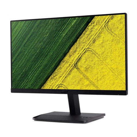
Datex-Ohmeda D-VNC15 Product manual

Datex-Ohmeda
VideoDisplay,D-VNC15(Rev.03)
S/5™VideoDisplay,D-VMC15(Rev.00)
VideoDisplay,D-VHC17(Rev.02)
S/5™21”DisplayMonitorUnit,D-VSC21(Rev.01)
S/5™LCDDisplay,D-LCC10A/W(Rev.01)
S/5™LCDDisplay,D-LCC15(Rev.00)
S/5™DisplayControllerBoard,B-DISP(Rev.01)
TechnicalReferenceManual
Allspecificationsaresubjecttochangewithoutnotice.
DocumentNo.8001004-1
June2001
Datex-OhmedaInc.
3030OhmedaDrive
53707-7550MADISON,WIS
USA
Tel.+1-608-2211551,Fax+1-608-2229147
www.us.datex-ohmeda.com
Datex-OhmedaDivision,
InstrumentariumCorp.
P.O.Box900,FIN-00031
DATEX-OHMEDA,FINLAND
Tel.+3581039411Fax+35891463310
www.datex-ohmeda.com
InstrumentariumCorp.Allrightsreserved.


Tableofcontents
DocumentNo.8001004-1
i
TABLEOFCONTENTS
DisplaysandControllerBoard
TABLEOF CONTENTS i
TABLEOF FIGURES iii
Introduction 1
1 Specifications 2
1.1 VideoDisplay,D-VMC15(Rev.00)............................................................................................................2
1.2 VideoDisplay,D-VNC15(Rev.03).............................................................................................................2
1.3 VideoDisplay,D-VHC17(Rev.01).............................................................................................................3
1.4 VideoDisplay,D-VHC17(Rev.02).............................................................................................................4
1.5 21”DisplayMonitorUnit,D-VSC21(Rev.02).............................................................................................4
1.6 LCDDisplay,D-LCC10A/W.......................................................................................................................5
1.7 LCDDisplay,D-LCC15(Rev.00)................................................................................................................5
1.8 DisplayControllerBoard,B-DISP...............................................................................................................6
2 FunctionalDescription 7
2.1 VideoDisplaysD-VMC15,D-VNC15,D-VHC17andD-VSC21.....................................................................7
2.2 LCDdisplay..............................................................................................................................................7
2.2.1 LCDinterfaceboard..........................................................................................................................8
2.3 Externalconnectorconfigurations..............................................................................................................9
2.4 DisplayControllerBoard,B-DISP.............................................................................................................11
2.4.1 Connectorsandsignals ..................................................................................................................13
3 Serviceprocedures 14
3.1 Generalserviceinformation.....................................................................................................................14
3.1.1 VideoDisplay, D-VMC15 ................................................................................................................14
3.1.2 VideoDisplay,D-VNC15.................................................................................................................14
3.1.3 VideoDisplay,D-VHC17.................................................................................................................14
3.1.4 VideoDisplay,D-VSC21.................................................................................................................14
3.1.5 LCDDisplay,D-LCC10A/W.............................................................................................................14
3.1.6 LCDDisplay,D-LCC15....................................................................................................................14
3.2 Servicecheck.........................................................................................................................................15
3.2.1 VideoDisplay, D-VMC15 ................................................................................................................15
3.2.2 VideoDisplay,D-VNC15.................................................................................................................17
3.2.3 VideoDisplay,D-VHC17.................................................................................................................20
3.2.4 VideoDisplay,D-VSC21.................................................................................................................23
3.2.5 LCDDisplay,D-LCC10A,WorkstationLCDDisplay,D-LCC10W.........................................................24
3.2.6 LCDDisplay,D-LCC15....................................................................................................................27
3.3 Disassemblyandreassembly..................................................................................................................29
3.3.1 LCDDisplay,V-LCC10A/W.............................................................................................................29
3.3.2 LCDDisplay,D-LCC15....................................................................................................................30
3.3.3 VideoDisplay, D-VMC15 ................................................................................................................31
3.3.4 VideoDisplay,D-VNC15.................................................................................................................31
3.3.5 VideoDisplay,D-VHC17.................................................................................................................31
3.3.6 VideoDisplay,D-VSC21.................................................................................................................31

S/5AnesthesiaMonitorandS/5CriticalCareMonitor
DocumentNo.8001004-1
ii
4 Troubleshooting 32
4.1 VideoDisplays,D-VMC15,D-VNC15,D-VHC17,D-VSC21.......................................................................32
4.2 LCDDisplays,D-LCC10,D-LCC15...........................................................................................................33
4.3 DisplayControllerBoards,B-DISP...........................................................................................................33
5ServiceMENU 34
5.1 Keyboardmenu......................................................................................................................................35
5.1.1 KeyboardLog.................................................................................................................................36
5.1.2 KeyboardType...............................................................................................................................36
6 SpareParts 37
6.1 14”VideoDisplay,D-VHC14...................................................................................................................37
6.2 15”VideoDisplay,D-VMC15..................................................................................................................37
6.3 15”VideoDisplay,D-VNC15...................................................................................................................38
6.3.1 15”VideoDisplay,D-VNC15Rev.00..............................................................................................38
6.3.2 15”VideoDisplay,D-VNC15Rev.01..............................................................................................38
6.3.3 15”VideoDisplay,D-VNC15Rev.02..............................................................................................38
6.3.4 15”VideoDisplay,D-VNC15Rev.03..............................................................................................39
6.4 17”VideoDisplay,D-VHC17...................................................................................................................39
6.4.1 17”VideoDisplay,D-VHC17Rev.00..............................................................................................39
6.4.2 17”VideoDisplay,D-VHC17Rev.01,02........................................................................................40
6.5 21”VideoDisplay,D-VSC21...................................................................................................................40
6.5.1 21”VideoDisplay,D-VSC21Rev.00..............................................................................................40
6.5.2 21”VideoDisplay,D-VSC21Rev.01..............................................................................................40
6.5.3 21”VideoDisplay,D-VSC21Rev.02..............................................................................................40
6.6 LCDDisplay,D-LCC10............................................................................................................................41
6.6.1 LCDDisplay,D-LCC10Rev.01.......................................................................................................41
6.6.2 LCDDisplay,D-LCC10Rev.02.......................................................................................................42
6.6.3 LCDDisplay,D-LCC10Rev.03.......................................................................................................43
6.6.4 LCDDisplay,D-LCC10Rev.04.......................................................................................................44
6.6.5 LCDDisplay,D-LCC10A,LCDDisplay,D-LCC10C,WorkstationLCDDisplay,D-LCC10WRev.00.......45
6.6.6 FrontPanelStickerforLCDdisplays................................................................................................46
6.6.7 S/5FrontPanelStickerforLCDdisplays.........................................................................................47
6.7 LCDDisplay,D-LCC15............................................................................................................................48
6.8 DisplayControllerBoards,B-DISP,B-DVGA,B-DHIGH..............................................................................48
7 EarlierRevisions 49
APPENDICESA-G
51
SERVICECHECKFORMVideoDisplay,D-VHC14............................................................................................A-1
SERVICECHECKFORMVideoDisplay,D-VMC15............................................................................................B-1
SERVICECHECKFORMVideoDisplay,D-VNC15............................................................................................C-1
SERVICECHECKFORMVideoDisplay,D-VNC17........................................................................................... D-1
SERVICECHECKFORMVideoDisplay,D-VSC21 ............................................................................................E-1
SERVICECHECKFORMLCDDisplay,D-LCC10A,LCDDisplay,D-LCC10C,WorkstationLCDDisplay,D-LCC10WF-1
SERVICECHECKFORMLCDDisplay,D-LCC15..............................................................................................G-1

Tableofcontents
DocumentNo.8001004-1
iii
TABLEOFFIGURES
Figure1 General block diagram, D-LCC10A/C(rev.01) 8
Figure2 LCD interface board block diagram,D-LCC10A/C 9
Figure3 DisplayControllerBoard, B-DISP,blockdiagram 12
Figure4 Exploded view, D-VNC14 38
Figure5 Exlploded view, VideoDisplay,D-VHC17 39
Figure6 Explodedview,LCDDisplay, D-LCC10 41
Figure7 Explodedview,LCDDisplay, D-LCC10Rev.03 43
Figure8 Explodedview,LCDDisplay,D-LCC10A,LCDDisplay,D-LCC10C,WorkstationLCDDisplay,D-LCC10W
Rev.00 45

S/5AnesthesiaMonitorandS/5CriticalCareMonitor
DocumentNo.8001004-1
iv

DisplaysandControllerBoards
DocumentNo.8001004-1
1
INTRODUCTION
Thissectionprovidesinformationaboutthemaintenanceandserviceofthefollowingproducts:
•LCDDisplays,D-LCC10A/W,D-LCC15
•Displaycontrollerboard,B-DISP
ServiceManualfor VideoDisplaysD-VMC15,D-VNC15,D-VHC17,andD-VSC21isnotavailable.

S/5AnesthesiaMonitorandS/5CriticalCareMonitor
2
DocumentNo.8001004-1
1SPECIFICATIONS
1.1 VideoDisplay,D-VMC15(Rev.00)
Dimensions
W×D×H 339×432×366 mm
Weight 15kg
CRT
Diagonal 15”
Facetreatment Black matrix withanti-reflection,antistatic
Deflectionangle 90°
Phosphor P22
Aperturegrillepitch 0.28mm
Resolution
Horizontal×Vertical 1024×768/75Hz
ElectricalRequirements
Linevoltage AC,90...264V,47…63Hz
Powerconsumption <110W
EnvironmentalRequirements
Ambienttemperature:
Operating +0°C...+40°C
Packed -20°C...+65°C
Relativehumidity:
Operating 10%...95%,non-condensing
1.2 VideoDisplay,D-VNC15(Rev.03)
Dimensions
W×D×H 362×400×381mm
Weight 14kg
CRT
Diagonal 15”
Facetreatment non-glare,antistatic
Deflectionangle 90°
Phosphor P22
Aperturegrillepitch 0.25mm
Resolution
Horizontal×Vertical 1024×768

DisplaysandControllerBoards
DocumentNo.8001004-1
3
ElectricalRequirements
Linevoltage AC,90...264V,Autosense,50/60Hz
Powerconsumption:
Normaloperation <100W
Stand-by ~70W
Suspend <15W
Autopoweroff <5W
EnvironmentalRequirements
Ambienttemperature:
Operating +10°C...+40°C
Packed -20°C...+60°C
Relativehumidity:
Operating 15%...85%
Packed 5%...95%
1.3 VideoDisplay,D-VHC17(Rev.01)
Dimensions
W×D×H 410×465×429mm
Weight 22kg
CRT
Diagonal 17”
Facetreatment Blackmatrix,invarshadowmask,Anti-Reflectioncoat
Deflectionangle 90°
Phosphor Shortpersistence phosphors
Aperturegrillepitch 0.22mm(optional0.24mm)
Resolution
Horizontal×Vertical 1280×1024
Electricalrequirements
SeepowerconnectionrequirementsrelatedtoS/5systemsfrom
PartI/Installation
.
Linevoltage AC,110...120/200...240V,
automatically select.Providedwithpowersavecircuit.
Powerconsumption 110W(nominal)
Warm-uptime 30minutestoreachoptimumperformancelevel.
Environmentalrequirements
Ambienttemperature:
Operating +10°C...+30°C
Storage -20°C...+60°C
Relativehumidity:
Operating 10%...80%
Storage 10%...90%

S/5AnesthesiaMonitorandS/5CriticalCareMonitor
4
DocumentNo.8001004-1
1.4 VideoDisplay,D-VHC17(Rev.02)
Dimensions
W×H×D 412×402×413.5mm
Weight 17.0kg/37lbs(app.)
CRT
Diagonal 17”
Facetreatment ARASCcoating
Deflectionangle 90°
Aperturegrillepitch 0.26mm(optional0.28mm)dot-pitch
Resolution
Horizontal×Vertical 1600×1200
Electricalrequirements
SeepowerconnectionrequirementsrelatedtoAS/3andCS/3systemsfrom
PartI/Installation
.
Powersupply 90...132VAC,60/50Hz,2.0A
180...264VAC,60/50Hz,1.2A(autoselect)
Powerconsumption 135Wmax.
Environmentalrequirements
Ambienttemperature:
Operating +5°C...+35°C
Relativehumidity:
Operating 10%...80%
1.5 21”DisplayMonitorUnit,D-VSC21(Rev.02)
Dimensions
W×D×H 515×544×490mm
Weight 31kg
CRT
Diagonal 53.3cm/21”fullsquare
Facetreatment CRTwithinvarshadowmask,
Dotpitch 0.28mm/0.22horizontal
Resolution
Horizontal×Vertical 1280×1024@90Hz
1600×1280@76Hz
Electricalrequirements
Linevoltage AC,90...260V/autosense,50/60Hz
Powerconsumption <160W

DisplaysandControllerBoards
DocumentNo.8001004-1
5
Environmentalrequirements
Ambienttemperature:
Operating +10°C...+40°C
Storage -20°C...+60°C
Relativehumidity:
Operating 15%...85%
Storage 5%...95%
1.6 LCDDisplay,D-LCC10 A/W
Displaysize 10.4in
Displaytype ActiveMatrixColorLCDDisplay
Resolution 640×480×(R,G,B)
Dimensions
Outline(ComWheelincluded)
W×D×H 315×74×265.5mm/12.4×2.9×10.5in
Weight 3.5kg/7.7lb
Electricalrequirements
AllLCDdisplayslistedcanbeconnectedtoB-DISPDisplaycontrollerboards.
Powerconsumption 14W
EnvironmentalRequirements
Operatingtemperature +10...+35°C/50-95°F
Storagetemperature -10...+50°C/14-122°F
Atmosphericpressure 660...1060hPa(660...1060mbar)
Humidity 0...85%non-condensing
1.7 LCDDisplay,D-LCC15 (Rev.00)
Displaysize 15indiagonal
Displaytype ActiveMatrixColorTFTLCDDisplay
Resolution XGA,1024x768
Dimensions
Outline(ComWheelincluded)
W×D×H 410x 100x355mm
Weight 5kg
Electricalrequirements
AllLCDdisplayslistedcanbeconnectedtoB-DISPDisplaycontrollerboards.
LineVoltage AC,90…264V,47…63Hz
Powerconsumption:
ON 40W
Stand-by 5W
Suspend 5W

S/5AnesthesiaMonitorandS/5CriticalCareMonitor
6
DocumentNo.8001004-1
EnvironmentalRequirements
Operatingtemperature +0...+40°C
Storagetemperature -20...+65°C
Atmosphericpressure 660...1060hPa(660...1060mbar)
Humidity 10...95%
1.8 DisplayController Board,B-DISP
Videooutput:bothconnectorsandbothresolutions,analogRGB,0.2V-1.1V,0,8Vpp,75ohm
Outputdata
Highresolution
Resolution 1984×512pixels
Framefrequency 65Hz
Scanfrequency 34.7kHz
Dotfrequency 80MHzmax.
Syncpolarity H/negative,V/negative,levelTTL
Syncpulse:
Horizontal Vertical
Frontporch 0.40µs 57.6µs
Syncperiod 1.20µs 115.2µs
Backporch 2.40µs 460.8µs
VGAresolution
Resolution 640×480pixels
Framefrequency 60Hz
Scanfrequency 31.6kHz
Dotfrequency 25MHzmax.
Syncpolarity H/negative,V/negative,levelTTL
Syncpulse:
Horizontal Vertical
Frontporch 0.640µs 0.349ms
Syncperiod 3.520µs 0.063ms
Backporch 1.920µs 1.019ms
Highresolution (Japan)
Resolution 1600×600pixels
Framefrequency 67Hz
Scanfrequency 41.7kHz
Dotfrequency 80MHzmax.
Syncpolarity H/negative,V/negative,levelTTL
Syncpulse:
Horizontal Vertical
Frontporch 0.40µs 57.6µs
Syncperiod 1.20µs 115.2µs
Backporch 2.40µs 460.8µs

DisplaysandControllerBoards
DocumentNo.8001004-1
7
2FUNCTIONALDESCRIPTION
2.1 VideoDisplays D-VMC15,D-VNC15, D-VHC17andD-VSC21
Thedisplaysaresuitableforhighendapplicationsusinggraphicalinterface.Theadjustmentsand
selectionsarecarriedoutthroughdisplays’internalmenus.Thedisplayssynchronizeandadjust
automatically withawiderangeofscanningfrequencies.
Thepowersupplysectionofthedisplaysdoesnotcontainseparatingtransformer,exceptD-VHC17
rev.00-01does.Therefore,thepowerfortheotherdisplaysshouldbesuppliedviaF-CU8orviaan
externalseparatingtransformer.
Allthedisplayscontainadegaussing(demagnetisation)circuitry.Degaussingtakesplace
automatically whenthemonitoristurnedon,however,thedegaussingcanbeactivatedalso
manuallyduringanoperation,ifnecessary.
2.2 LCDdisplay
NOTE:TheLCDdisplaybacklightcircuitrunsonahighvoltage.Donottouchtheadapterboard
whenpowered.
LCDDisplay,D-LCC10includesLCDdisplaymodule,LCDinterfaceboard,andkeyboard.The
displaykeyboardworksindependentofthemainkeyboard.
LCDDisplay,D-LCC15includesLCDdisplaymoduleandLCDinterfaceboard.
TheLCDDisplay isconnectedtoB-DISPDisplaycontrollerboardinthemonitorframewiththeLCD
displayinterfacecable.Theinterfacecableisavailableasanaccessory.Seeaccessorycatalogue.
VideosignallingbetweentheDisplaycontrollerboardB-DISPandtheLCDDisplaytakesplacein
analogform.IncomingsignalsarebufferedintheInterfaceboard,convertedintodigitalform,and
fedforwardtotheLCDDisplaymodule.
CommunicationbetweentheDisplaycontrollerboardandtheCommandboardtakesplacein
RS232serialcommunicationchannelD.
NOTE:D-LCC10A/CandD-LCC15require B-DISP.

S/5AnesthesiaMonitorandS/5CriticalCareMonitor
8
DocumentNo.8001004-1
Figure1 General block diagram, D-LCC10A/C(rev.01)
2.2.1 LCDinterfaceboard
TheLCDInterfaceboardistheinterfacebetweenthedisplaycontrollerboardandtheLCDdisplay
component.ThekeyboardisalsoconnectedtotheInterfaceboard,seefigure1.
TheincomingsignaltoLCDInterfaceboardispureanalogVGA-RGBwithseparatehorizontaland
verticalsynchronisationsignals,see figure2.ThedisplayelementusesdigitalRGB-signals,
HSYNC,VSYNC,DOTCLKandadisplaytimingsignalDTMG.TheDTMGsignalindicatesthatthe
digitalRGB-signalsareactive.
Thefunctionsofthisboardaredigitalizationofthevideosignals,regenerationoftheDOTCLKand
generationoftheDTMG.Thebacklightdriverisalsolocatedontheboard.
Powersupply,D-LCC10A/C
TheDC/DCpowersupplyisanisolateddiscontinuousmodeflybackswitcher.Ithasacurrent
modePWMcircuitandaseparateFETswitchontheprimaryside.Thetransformerhastwo
secondarywindings,onefor5Vandanotherfor12V.Onthesecondaryside (5V),thereisa
separatechiponthefeedbackpathtodrivetheoptoisolator.

DisplaysandControllerBoards
DocumentNo.8001004-1
9
Backlightunit,D-LCC10A/C
Thebacklightunitconsistsoftwochangeabletubesfedbyseparateinverterboard.
Backlight
inverter
Digital
BUS
buffer
Video
Video
Video
Amplifier
/792
Phase
detector VCOLP
filter
POWER
+5V
32V
+12V
ON/
STBY
control
Logic to generate
DTMG -signal
HSYNC
VSYNC
R
G
B
VBUS
GND
ON/STBY
5VKb
12VINV
5VKb
+5V
DTMG
LCD
Display
Element
Keyboard
CCFL
Backlight
Amplifier
Amplifier
Figure2 LCD interface board block diagram,D-LCC10A/C
2.3 Externalconnectorconfigurations
Mainconnector on LCD display, D-LCC10A/W
PinNo I/O Signal Notes
1 I DirtyGround
2I Intensity
3 I Hsync2 horiz.Deflect
4 I Vsync2 vert.Deflect
5 I Contrast
6 I +32Vdd
7 I GND
8 O RXDDRS232 fromkeyboard
9 I TXDDRS232 tokeyboard
10 I ON/STBY activeGND
A1 I BLUEGND &BLUEVIDEO2
A2 I GREENGND&GREENVIDEO2
A3 I REDGND&REDVIDEO2

S/5AnesthesiaMonitorandS/5CriticalCareMonitor
10
DocumentNo.8001004-1
Connectoron D-LCC15 and D-VMC15,onD-VNC15andonD-VHC17
PinNo Signal
1<-RV Red
2 <- GV Green
3<-BV Blue
4 -> ID2 MonitorIdentification(LG)
5<-ST Selftest
6 <- RG Ground(red)
7 <- GG Griund(green)
8 <- BG Ground(blue)
9-- -
10 - LG Ground(logic)
11 -> ID0 MonitorIdentification(LG)
12 -> ID1 MonitorIdentification(N.C.)
13 <- HS Horizontalsync.
14 <- VS Verticalsync.
15 - - Notused
Connectorat the end of interfacecable(DisplayControllerBoardside)
PinNo I/O Signal Note
1
2
3
4
5
6
7
8
9
10
11
12
13
14
15
16
17
18
19
20
21
22
23
24
25
26
O
O
O
O
O
O
O
O
O
O
O
O
O
I
O
O
O
REDVIDEO2
GREENVIDEO2
BLUEVIDEO2
BLANK
GND
Hsync2
Vsync2
REDGND
GREENGND
BLUEGND
GND
DCLKGND
notconnected
ON/STBY
DirtyGND
DirtyGND
RXDDRS232
TXDDRS232
notconnected
notconnected
notconnected
notconnected
+32Vdd
+32Vdd
notused
chassis
horiz.deflect
vert.deflect
chassis
activeGND
fromkeyboard
tokeyboard

DisplaysandControllerBoards
DocumentNo.8001004-1
11
2.4 DisplayController Board,B-DISP
B-DISPboardisconnectedtotheCPUMotherboard.TheprocessorontheCPUboardtransmits
programthroughtheCPUbustoB-DISPboard.
B-DISPboard includes the functions ofbothB-DHIGHandB-DVGAboards.Thus,B-DISPboard
supportsbothhighresolutionandVGAresolution.Theresolutionisautomatically selectedbased
onmonitorIDcodes.Theresolutionissetto640x480ifaVGAresolutiondisplayisused,otherwise
theresolutionissetto1984x512.
NOTE:S-ANE97/98/99,S-ICU97/98/99andS(L)-ARK97/98/99softwaressupportB-DISP,B-
DHIGHandB-DVGAboards.If,however,B-DISPboardisusedtodriveD-VHC14display,asmall
partoftheresultingpicturewillbeclipped.
Systemmemory
ThesystemmemorycontainstheGSPsoftwarecode.Thememoryconsistsoftwo256kx16
memorybanks.
Framememory
Theframememorycontainsdigitaldisplaydata.Thesizeofthememoryis1MBmaking1984x
512display resolutionwith256colorspossible.Thememoryconsistsoffour256kx8VRAM
memorycircuits.
Videointerfacepalette
Thevideointerfacepalettereadsthedigitaldisplay datafromtheframememoryandconvertsthe
dataintoanalogRGB-signals.Thesynchronizationsignalsfortheconversionaregeneratedby the
GSP.
Thevideointerfacepaletteisclockedbytwopixelclocks.A25MHzclockisselectedforVGA
resolutionanda40MHzclockisselectedforhighresolution.The40MHzclockisinternally
convertedintoa80MHzclock.
GraphicsSystem Processor (GSP)
Therearefour16-bitregistersintheGSP,fromwhichthehost-processorreadsandtowhichit
writesdata.
DisplayController Resolution
Theresolutionofthedisplay controllerdependsoninitializationofthe GSP'sregistersand
frequencyofthevideooscillator.
ResetSignal
ResetsignalcomesfromthepowersupplyunitthroughtheCPUbus.

S/5AnesthesiaMonitorandS/5CriticalCareMonitor
12
DocumentNo.8001004-1
MonitorID register
ThemonitorIDregistercontainsathreebit(numericvalues0-7)monitorIDcode.Theregisteris
connectedtochannels11-13oftheX3D-connector.IfnodisplayisconnectedtoB-DISPboardor
ifthemonitorIDcodefails,111codeisgeneratedbypull-upresistors.IftheIDcodeis011or
101,VGAresolutionisselected,otherwisehighresolutionisselected.
Figure3 DisplayControllerBoard, B-DISP,blockdiagram

DisplaysandControllerBoards
DocumentNo.8001004-1
13
2.4.1 Connectorsandsignals
15-pinD-connector on Display Controller Board,B-DISP,X2
PinNo I/O Signal Note
1
2
3
4
5
6
7
8
9
10
11
12
13
14
15
O
O
O
O
O
O
O
O
O
O
REDVIDEO1
GREENVIDEO1
BLUEVIDEO1
MON1ID2
GND
REDGND
GREENGND
BLUEGND
N/C
SYNCGND
MON1ID0
MON1ID1
HSYNC1
VSYNC1
N/C
analog
analog
analog
monitoridentification
monitoridentification
monitoridentification
TTL,CMOS
TTL,CMOS
26-pinD-connector on Display Controller Board,B-DISP
PinNo I/O Signal
1
2
3
4
5
6
7
8
9
10
11
12
13
14
15
16
17
18
19
20
21
22
23
24
25
26
O
O
O
I
I
O
I
O
O
O
O
O
O
O
O
I
O
O
I
O
O
O
O
O
O
Redvideo(analog)
Greenvideo(analog)
Bluevideo(analog)
MON2ID2
MON2ID1
Ground
MON2ID0
Horizontalsync
Verticalsync
Redground
Greenground
Blueground
Ground
Ground/Syncground
+5V
ON/STBY
Ground
Ground
RxDRS232
TxDRS232
Brightness
Contrast
Audbufout
Notconnected
+32Vd
+32Vd

S/5AnesthesiaMonitorandS/5CriticalCareMonitor
14
DocumentNo.8001004-1
3SERVICEPROCEDURES
3.1 Generalserviceinformation
Fieldserviceislimitedtoreplacingfaultycircuitboardsormechanicalparts.Thecircuitboardsare
thenreturnedtoDatex-Ohmedaforrepair.
Datex-OhmedaTechnicalServicesisalwaysavailableforserviceadvice.Pleaseprovidetheunit
serialnumber,fulltypedesignationandadetaileddescriptionofthefault.
CAUTION Thetestsandrepairsoutlinedinthissectionshouldonlybeattemptedbytrained
personnelwiththeappropriateequipment.Unauthorizedservicemayvoidwarranty
oftheunit.
3.1.1 VideoDisplay, D-VMC15
Fieldserviceislimitedtobasicadjustmentsthroughthedisplay’skeysandtoreplacing
mechanicalpartsofthedisplaystand.
IncaseofadisplayfailurecontactDatex-OhmedaTechnicalServicesforapossibilitytorepairthe
displayatalocalrepaircompany.
ThedisplaycanalwaysbereturnedtoDatex-Ohmedaforrepair.
3.1.2 VideoDisplay, D-VNC15
Fieldserviceislimitedtobasicadjustmentsthroughthedisplay’skeysandtoreplacing
mechanicalpartsofthedisplaystand.
IncaseofadisplayfailurecontactDatex-OhmedaTechnicalServicesforapossibilitytorepairthe
displayatalocalrepaircompany.
ThedisplaycanalwaysbereturnedtoDatex-Ohmedaforrepair.
3.1.3 VideoDisplay, D-VHC17
Fieldserviceislimitedtobasicadjustmentsthroughthedisplay’skeysandtoreplacing
mechanicalpartsofthedisplaystand.
ThedisplayshouldbereturnedtoDatex-Ohmedaforrepair.
3.1.4 VideoDisplay, D-VSC21
Fieldserviceislimitedtobasicadjustmentsthroughthedisplay’skeys.
ThedisplayshouldbereturnedtoDatex-Ohmedaforrepair.
3.1.5 LCDDisplay,D-LCC10A/W
Thebacklighttubes(2pcs)arereplaceable.
3.1.6 LCDDisplay, D-LCC15
Thebacklighttubes(2pcs)arereplaceableinsomemodels.
This manual suits for next models
7
Table of contents
Popular Monitor manuals by other brands
Panasonic
Panasonic BTLH2550E - LCD VIDEO MONITOR operating instructions
Avalue Technology
Avalue Technology IPM-21 Quick reference guide
LG
LG Flatron L1922P user guide
Dell
Dell 2407WFP - UltraSharp - 24" LCD Monitor user manual
Sony
Sony SDM-H246W operating instructions
Tektronix
Tektronix 1741C Technical reference
