Dato CSST13020 User manual

SCREW AIR
COMPRESSOR
CSST13020
Instruction
Manual
Release August 2018


1
TABLE OF CONTENTS
1. Safety Information…………………...………………………………………………4
1.1 Safety Alert Symbols………………………………………………………………4
1.2 Safety Precautions………………………………………………...………………...5
1.3 Pressure……………………………………..……………………………………….5
1.4 Fire and Explosion…………………………..……………………………………...6
1.5 Moving Parts………………………………………………..………………………6
1.6 Hot Surfaces…………………………….………………………….……………….6
1.7 Proper Compressed Air Applications.................................................6
1.8 Electrical Shock……………………………………………….…………………….7
2. General Information……………………………………………………………………8
2.1 Introduction…………………………………………………………………………8
2.2 The Compression Cycle…………………………………………………………….9
2.3 Compressor Lubrication and Cooling System…………………………..……...10
2.4 Compressor Discharge System…………………………………….……………..10
2.5 Air-end, Inlet Valve and Filtration System…………………………………….11
2.6 Control Panel Layout...…………………………………………………………..12
2.7 Technical Data…………………………………………………………….. 14
3. Fluid Information……………………………………………………………………..15
3.1 Fluid Guide………………………………………………………………….……..15
3.2 Fluid Change and Recommendations……………………………………....……15
4. Installation……………………………………………………………………………..16
4.1 Compressor Mounting, Support and Location…………………………………16
4.2 Ventilation and Cooling……………………………………….…………………16
4.3 Piping Connection………………………………………………………..............18
4.4 Fluid Level Inspection………………………………………….…………………19
4.5 Electrical………………………………………..…………………………………19
4.6 Motor Rotation Inspection…………………………………………...…………...20
4.7 Fan Rotation Inspection …………………………………………….……………21
5. Operation…………………………………………………………………….………...22
5.1 Routine Operation…………………………………………….…………………..22
5.2 Operating Procedures (Electrical Control Panel)………………………………24
5.3 Display Unit Status and Operations……………………………………………24
5.4 Customer Parameter and Functions………………………………….…………27

2
TABLE OF CONTENTS
5.5 Manufacturer Parameters……………………………………………………….31
5.6 Control Principle………………………………………………….…………...39
5.7 Network Control…………………………………………………………………41
5.8 Temperature Control of Fan………………………………………….………….41
5.9 Failure Shutdown and Emergency Shutdown…………………………………..41
5.10 Early-Warning and Prompts………………………………………..…………...41
5.11 Control Protection……………………………………………………….............42
5.12 Common Failure Solving………………………………………...…………..44
5.13 Electrical Control Diagram ……………………………………………...……46
6. Servicing………………………………………………………………………………..47
6.1 Fluid Change………………………………………………………………..……..47
6.2 Air Filter……………………………………………………………………….…..47
6.3 Fluid Filter………………………………………………………………………....48
6.4 Air/Oil Separator………………………………………………………………….48
6.5 Maintenance Schedule…………………………………………………………….49
7. Troubleshooting Guide.………………………………………………………………50
8. Standard Terms and Conditions ……………………………………………….…..53

3
Safety Information
Thank you for choosing our Compressor. Please read this instruction manual carefully
before using the compressor. This manual must be kept in the safe place for future
reference. Our Compressor’s authorized distributors provide maintenance service for CS
series rotary screw compressors. A certified technician is required to ensure compressors
maintenance is safely handled. By following the instructions in this manual, the user will
minimize possibility of an accident throughout the useful life of this equipment.
1.1 SAFETY ALERT SYMBOLS
Key hazards are used throughout this manual. The level of hazards seriousness is
symbolized as follows:
This symbol identifies immediate
hazards which will result in severe
personal injury, death or substantial
properly damage.
This symbol identifies hazards or
unsafe practices which could
result in personal injury, death or
substantial property damage.
This symbol identifies immediate
electrical hazards which will result
in severe personal injury, death or
substantial properly damage.
This symbol identifies hazards or
unsafe practices which could
result in personal injury or
substantial property damage.
This symbol identifies immediate
hot surface hazards which will
result in severe personal injury.
NOTICE
Identifies important installation,
operation or maintenance
information which is not hazard
related.

4
Safety Information
1.2 SAFETY PRECAUTIONS
This manual describes the safety precautions, structure and functions of all systems and
components, as well as the operation and maintenance methods for the GC series rotary
screw air compressors. The owner and operator shall read the manual carefully. Only after
thorough understanding should the machine be operated for the first time. This manual
gives you a general description of the, mechanical and electrical systems and maintenance.
However, if you have any questions about operating and maintenance of the compressor;
please contact your authorized distributor or our service department personnel.
Do not modify the compressor and/or controls in any way except with written factory
approval. While not specifically applicable to all types of compressors with all types of
prime movers, most of the precautionary statements contained herein are applicable to most
compressors and the concepts behind these statements are generally applicable to all
compressors.
Failure to follow any of these precautions may results in severe personal injury,
death, property damage and/or compressor damage
1.3 PRESSURE
A properly sized pressure relief valve must be installed in the discharge piping ahead
(upstream) of any shutoff valve (block valve), heat exchanger, orifice or any potential
blockage point. Failure to install a pressure relief valve could result in the rupturing or
explosion of some system component. Relieve all pressure internally to the compressor
prior to servicing. Do not depend on check valves to hold system pressure. Do not change
the pressure setting of the pressure relief valve, restrict the function of the pressure relief
valve, or replace the pressure relief valve with a plug. Over pressurization of system or
compressor components can occur, resulting in death, severe personal injury or property
damage. Do not operate the compressor at pressures in excess of its rating. Never use
plastic pipe, rubber hose, or soldered joints in any part of the compressed air system.
Failure to ensure system compatibility with compressor piping is dangerous.

5
Safety Information
1.4 FIRE AND EXPLOSION
Clean up any spills of lubricant or combustible liquid immediately. Keep sparks and flame
away from the compressor. Do not permit smoking during servicing, such as checking or
adding fluid. Wipe down spills immediately using industrial cleaner as required. Do not use
flammable material for cleaning purposes. Do not operate the compressor in a hazardous
environment unless the compressor has been specially designed for that environment. Wear
personal protective equipment including safety goggles and clothing during servicing the
compressor. Never use a flammable or toxic solvent for cleaning the air filter or any parts.
1.5 MOVING PARTS
Keep hands, arms and cloths away from the coupling and fans of the compressor. Do not
remove any guards or cabinet panels or attempt to service any compressor part while the
compressor is operating.
1.6 HOT SURFACES
Do not touch any hot surface and parts during the compressor’s operation. Keep all body
parts away from air/oil receiver tank, steel tubing, air end and after-cooler. Wear personal
protective equipment including gloves while servicing the compressor.
1.7 PROPER COMPRESSED AIR APPLICATIONS
Air from this compressor will cause severe injury or death if used for breathing or food
processing. Air used for those processes must meet OSHA and applicable industry
regulations. This compressor is designed for use in the compression of normal atmospheric
air only. No other gases, vapors or fumes should be exposed to the compressor intake, nor
processed through the compressor. Keep personnel away from the compressed air discharge.
Use compressed air for cleaning purpose, only with effective chip guarding and personal
protective equipment which meet OSHA standard and/or any federal, state, local codes,
standard and regulation.

6
Safety Information
1.8 ELECTRICAL SHOCK
Never start the compressor unless it is safe to do so. Do not attempt to operate the
compressor with a known unsafe condition. Tag the compressor and render it inoperative
by disconnecting and locking out all power at the source or otherwise disabling its prime
mover so others who may not know of the unsafe condition cannot attempt to operate it
until the condition is corrected. Install, use and operate the compressor only in full
compliance with all pertinent OSHA regulations and/or any applicable Federal, State, and
Local codes, standards and regulations. Never assume it is safe to work on the compressor
because it is not operating. Many installations have automatic start/stop controls and the
compressor may start at any time.
NOTICE
- Follow all maintenance procedures and check all safety devices on schedule.
- Use the correct compressor fluid at all time
- Do not rely on the discharge check valve to isolate the compressed air service line
- Keep panels closed at all times and stay away from hot surfaces to prevent hazards
NOTICE
These instructions, precautions and descriptions cover GC series air compressors.
As a service to our customers, we often modify or construct packages to the
customer’s specifications. This manual may not be appropriate in those cases.
Every effort has been taken to ensure complete and correct instructions have been included
in this manual. However, possible product updates and changes may have occurred since
printing this manual. Compressor reserves the right to change specifications without
incurring any obligation for equipment previously or subsequently sold.

7
General Information
2.1 INTRODUCTION
The GC series offer models with power ranging from 7.5 kw to 132 kw. The compressor is
a single stage, positive displacement, fluid-flooded rotary screw. A complete unit of
following:
⚫Screw air compressor
⚫Dryer(optional)
⚫Filters(optional)
⚫Air tank(optional)
All components are assembled on a structural steel base with enclosure. The control panel
is located in the front of the enclosure door panel. Acoustical enclosure is one of the
standard features for all compressors.
NOTICE!
Dismantling the compressor’s enclosure may void its warranty.
General Information

8
2.2 THE COMPRESSION CYCLE
The compressor housing contains of two rotors; Male and
Female rotors. The male rotor has five lobes and female rotor
has six flutes. They are constantly and precisely meshed, and
housed in the cylinder with two parallel adjoining bores. All
parts are machined to exacting tolerances. The rotors provide
positive-displacement internal compression smoothly and
without surging. As the rotors rotate, air is drawn into the
cylinder through the inlet port. A volume of air is filled and
trapped as the rotor lobes pass the inlet port in the cylinders.
Compression occurs as the male rotor rolls into the female
flute, progressively reducing the space thereby raising the
pressure. Compression continues until the lobe and flute pass
the discharge port. The compressed air is then discharged into the air/oil separator tank.
There are five complete compression cycles for each complete rotation of the male rotor.
When the compressor is operating, a partial vacuum is produced at the compressor inlet.
Fluid is injected into the compressor unit and mixed with the air. The fluid has three basic
functions:
•As a coolant, it controls the rise in air temperature normally associated with the heat
of compression.
•It seals the leakage paths between the rotors and stator and also between the rotors
themselves.
•It acts as a lubricating film between the rotors allowing one rotor to directly drive
the other, which is an idler.
After air/fluid mixture is discharged from compressor to the reservoir, fluid is separated
from the air in the separator tank. Compressed air then flows through the after-cooler for
moisture removal while the lubricant is being cooled by the fluid-cooler for re-injectio
General Information

9
2.3 COMPRESSOR LUBRICATION AND COOLING SYSTEM
The lubrication and cooling system consists of a reservoir, centrifugal fan, fan motor,
aluminum finned fluid-cooler and after-cooler, thermal valve & fluid filter. High pressure
forces the lubricant through a series of direction changes in the reservoir where it is
separated from the air. The fluid is then delivered to the thermal valve and fluid-cooler.
Cooled fluid will be filtered before being re-injected back into the compressor.
Ambient air is being forced through the cooler fins by the centrifugal fan, which cools the
fluid and compressed air in the cooler tubes. The after-cooler helps separate the water
content in the discharge air, and through the automatic condensate drain, the water will be
drained. This avoids water contamination problems downstream (in service lines). Cooler
fins must be kept clean at all times.
Fluid from reservoir circulates to the thermal valve. The thermal valve is fully closed when
the fluid temperature is below 70°C (158°F). Fluid (below 158°F) will bypass the thermal
valve and inject directly to the airend. As the discharge temperature rises above 80°C
(176°F), due to heat of compression, the thermal valve begins to open and fluid will be
circulated to the cooler.
2.4 COMPRESSOR DISCHARGE SYSTEM
Air/fluid mixture has been forced into reservoir after compression. The reservoir has two
basic functions:
•It acts as a primary fluid separator.
•It serves as the compressor fluid sump.
The compressed air/fluid mixture enters the reservoir and is directed against the internal
baffle. Turbulent flow occurs and velocity is significantly reduced, thus causing large
droplets of fluid to form and fall to the bottom of reservoir. Fluid collected in the reservoir
will then be returned to the compressor due to the pressure differential.
The sight glass enables the operator to visually monitor the reservoir fluid level. Fluid is
added to the reservoir by removing the fluid filling cap after all system pressure is relieved.
The fluid level should remain at the top red lines on the sightglass. Fluid refill is required
once its level drops below the lower red line.
General Information

10
The minimum pressure check valve assures the reservoir maintains a minimum pressure
between 58 psig and 72 psig (4Bar and 5Bar) during unloading conditions. This pressure is
necessary for air/fluid separation and fluid circulation.
2.5 AIREND, INLETVALVE AND FILTRATION SYSTEM
The compressor inlet system consists of a Kerry air filter, Kerry inlet valve. & SKKairend.
The Kerry inlet valve controls the air intake volume. It is also acts as the check valve to
prevent the reverse pressure and rotation when compressor is shutting down.
General Information
SKKair end
Kerry inlet valve
Casing for Kerry air filter
11
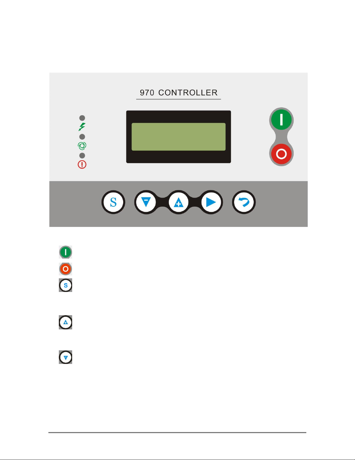
2.6 CONTROLLER PANEL LAYOUT
Standard GC compressor is equipped with microprocessor control panel.
Figure 1.1.1
——Start Button: Press this button to start the compressor.
——Stop button:Press this button to stop the compressor.
——Set Button/ Loading / unloading Button: After modification, press this to
confirm and save modified data;When the compressor is running ,press
this button to load or unload under a certain pressure.
——Move up button/increase button: Data at current position is increased by
pressing this button when data are modified; Menu is moved upwards when
menu is selected.
——Move down button / Descending button: Data at current position is
descended by pressing this button when data are modified; menu is moved
downwards when menu is selected.
General Information
12
——Shift button /Enter button: This button services as shift button when data
are modified and services as enter button when menu is selected.
——Back button / Reset button: This button services as back button when operate
menu to come back parent menu; resetting is carried out by pressing this button for
a little long time when failure shutdowns
Always check power supply before you service the unit. The power
indication light could be in faulty status.
General Information

13
2.7 TECHNICAL DATA
The specification of the models are as follow
Model
Pressure
Capacity
Main Motor
Exhaust connection
Weight
Dimensions
bar
m3/min
KW
kg
mm
GC7.5-8
0.8
1.2
7.5
G3/4
470
800×620×800
GC7.5-8G
0.8
1.2
7.5
G3/4
200
1020×820×1150
GC11-8
0.8
1.7
11
G1
370
1020×820×1150
GC11-10
1.0
1.5
11
G1
370
1020×820×1150
GC11-13
1.3
1.2
11
G1
370
1020×820×1150
GC15-8
0.8
2.4
15
G1
380
1020×820×1150
GC15-10
1.0
2.2
15
G1
380
1020×820×1150
GC15-13
1.3
1.7
15
G1
380
1020×820×1150
GC18-8
0.8
3.0
18
G1 1/2
500
1080×880×1235
GC18-10
1.0
2.7
18
G1 1/2
500
1080×880×1235
GC18-13
1.3
2.3
18
G1 1/2
500
1080×880×1235
GC22-8G
0.8
3.6
22
G1 1/2
560
1410×850×1235
GC22-8
0.8
3.6
22
G1 1/2
540
1410×850×1235
GC22-10
1.0
3.2
22
G1 1/2
540
1410×850×1235
GC22-13
1.3
2.7
22
G1 1/2
540
1410×850×1235
GC30-8
0.8
5.0
30
G1 1/2
650
1120×930×1290
GC30-10
1.0
4.4
30
G1 1/2
650
1120×930×1290
GC30-13
1.3
3.6
30
G1 1/2
650
1120×930×1290
GC37-8G
0.8
6.0
37
G1 1/2
740
1530×900×1435
GC37-8
0.8
6.0
37
G1 1/2
730
1530×1030×1435
GC37-10
1.0
5.5
37
G1 1/2
730
1530×1030×1435
GC37-13
1.3
4.6
37
G1 1/2
730
1530×1030×1435
GC45-8
0.8
7.1
45
G1 1/2
820
1240×1030×1595
GC45-10
1.0
6.5
45
G1 1/2
820
1240×1030×1595
GC45-13
1.3
5.6
45
G1 1/2
820
1240×1030×1595
GC55-8
0.8
9.5
55
G1 1/2
1200
1540×1200×1470
GC55-10
1.0
8.5
55
G1 1/2
1200
1540×1200×1470
GC55-13
1.3
7.4
55
G1 1/2
1470
1540×1200×1470
GC45-8GH
0.8
7.1
45
G1 1/2
970
1700×1050×1255
GC55-8GH
0.8
10.0
55
G1 1/2
1180
1790×1050×1255
GC75-8GH
0.8
13
75
G2
1470
2000×1200×1500
GC90-8GH
0.8
16
90
G2
1520
2000×1200×1500
GC110-8GH
0.8
20
110
G2
2210
2410×1300×1670
GC132-8GH
0.8
22
132
G2
2370
2410×1300×1670

14
Fluid Information
3.1 FLUID GUIDE
GC compressors are filled & tested with Kerry lubricant. Refer Figure 3-1 for filler port,
sightglass, quarter-turn valve location on the reservoir. The compressor is filled with the
manufacturer’s recommended quantity of Kerry fluid. Inspection of the reservoir fluid level
during installation or operation is recommended.
Figure 3-1: Fluid Fill Locatio
Do not use different fluid. Using different fluid will void compressor’s warranty.
3.2 FLUID CHANGE RECOMMENDATIONS
LUBRICANT
FLUID CHANGE
FLUID FILTER
CHANGE
SEPARATOR
CHANGE
Kerry 4000
Or equivalence*
Every 4,000 hours
Every 2,000 hours
Every 3,000 hours

15
Installation
4.1 COMPRESSOR MOUNTING, SUPPORT AND LOCATION
Compressor should be located on a flat surface in a clean, well-lit and well ventilated area.
The location must have sufficient access for maintenance equipment and lifting vehicle.
Four feet (4’) of clearance around the compressor is recommended for daily inspection and
easy access to all compressor components. The area must have sufficient lighting for
technicians to safely operate the compressor as well as perform maintenance work. The
location should be free from standing water.
The compressor’s base must be securely bolted to the floor with lag bolts. Rubber pad with
5 - 15mm thickness or pliable material should be placed under the bottom of the base if
floor surface is uneven or irregular. A stationary compressor will prevent accidents such as
broken piping or electrical connections. Do not over tighten the lag bolts because this may
cause the frame to twist or bind which could results in possible breakage of fluid coolers,
piping and the reservoir.
NOTICE!
Brand new compressor has “Orange Color” shipping bracket installed under
airend assembly. Please remove the bracket after the unit is installed.
Removal or paint over of safety labels will be a safety hazard. This could result in
personal injury or property damage. Warning signs and labels should be conspicuous
and on a bright legible surface. Do not remove any warning, caution or instructional
material attached with unit.
4.2 VENTILATION AND COOLING
Ambient temperature should not exceed 40°C (104°F). High ambient temperatures
may result in high air temperature shutdown.

16
Installation
NOTICE!
Do not install and operate compressor if the ambient temperature is below
5°C (41°F). Pre-heat option must be installed with the unit for lower ambient
temperatures.
The compressor air inlet must be located in the opposite direction to other compressors or
heat generating equipment. The object is to avoid hot air being drawn into the system. Do
not block the exhaust air from cooler or fan. Hot exhaust air must be vented outside through
a duct to prevent high ambient room temperature. The compressor room must be properly
ventilated to avoid compressor high temperature shutdown.
Maintain clean & fresh air, dust free, metal particle free and chemical vapor
free in the compressor’s room. Housing the compressor within a poorly
ventilated enclosure will cause higher operating temperature.
Under no circumstances should a compressor be installed in an area exposed to
toxic, volatile or corrosive atmosphere, nor should toxic, volatile or corrosive
agents be stored near the compressor.
All models are intended for indoor installation; however, it is possible, with certain
modifications, to accommodate some outdoor locations. Models with standard enclosure
are water-resistant but not water tight. Shelter is needed to protect the unit from rain, snow
and freezing temperatures. An optional weather hood or air grille could be installed to
protect compressor against blowing rain and snow as well as cabinet heater additions if
ambient temperature will be below 5°C (41 F).

17
Installation
4.3 PIPING CONNECTION
Before installation, review the complete air systems layout, which includes compressor(s),
receiver tank, dryer(s), line filter(s), pipe size, water drain and isolator valves. Never join
pipes or fittings by soldering. Never use PVC pipe or non-genuine rubber hose in the air
system. Use flexible connections to prevent pipe load from being transmitted to the
compressor. Never use a different pipe size other than the manufacturer specification for
the compressor unit.
A service line shut off valve must be installed after the compressor air outlet connection
with a pressure relief valve installed to release compressed air to the atmosphere. For a
single compressor and air receiver tank, manual shut off valves are typically being installed.
A union connector must be installed after the ball valve (quarter turn, shut off valve) at the
compressed air outlet. This will allow unit isolation for maintenance.
Release system pressure by opening manual pressure relief valve prior to
servicing. Failure to relieve system pressure could result in death or serious
injury and property damage.
The compressor after-cooler comes with an automatic condensate drain. The drain line
should be installed to remove the condensate during compressor operation.
A receiver tank should be installed if compressed air demands fluctuate. Service line piping
is recommended to be sized to match the compressor’s discharge connector. All piping &
fittings should be rated to withstand greater pressure than the discharge pressure. Isolation
valves & drain valves are installed to isolate the compressor when service is required.
These valves should have water drip legs with the drain direction facing downward to the
floor. Piping should all line up properly with an adequate loop radius or bend radius given
for easy installation and to prevent bending stress, flow restriction and damage due to
thermal expansion. Piping support brackets must be mounted independent of the
compressor and motor. This will avoid damage caused by vibration.

18
Installation
Pressure relief valves are sized to protect the system. Never change the pressure setting or
tamper with the valve. Only the valve manufacturer and their authorized representatives are
allowed to make such changes.
Pressure relief valves are used to protect system integrity in accordance with
safety standards. Failure to provide properly sized valves will result in death or
serious injury.
Pressure relief valves are installed prior to any potential blockage point such as shutoff
valves, heat exchangers and discharge silencers. Ideally, the valve should be threaded
directly into the pressure point it is sensing, not connected with tubing or pipe. Always
direct discharge from relief valves to a safe area away from personnel.
4.4 FLUID LEVEL INSPECTION
Inspect the fluid level when the compressor is in shut down mode. Fluid level is indicated
on the reservoir sight glass (see figure 3-1). The maximum fluid level is at the top red-mark.
Add fluid until the top red-mark is reached.
4.5 ELECTRICAL
Before installation, the electrical supply should be checked for adequate wire size and
capacity. User must comply with national & local electrical codes. The codes specify the
surrounding clearance requirement for the electrical panel. Wiring work should be
undertaken only by a qualified electrician in compliance with OSHA, national or local
electrical code. GC compressor provides wiring diagrams for user reference. Refer to the
electrical control schematic in the parts manual for wiring diagrams. Genuine fused
disconnect switch or circuit breaker should be purchased from the manufacturer. Any
unreasonable voltage imbalance (5%) between phases must be eliminated and low voltage
problems must be corrected to prevent excessive current draw. Air compressors must be
grounded in accordance with applicable codes, regulations and requirement.
Installation
Table of contents
Popular Air Compressor manuals by other brands

Elektra Beckum
Elektra Beckum Basic 270 Handleiding

Johnson Controls
Johnson Controls SAB 355 Engineering manual

EINHELL
EINHELL 40.206.55 Original operating instructions

Scheppach
Scheppach HC55 Translation from the original instruction manual

Solid State Logic
Solid State Logic THE BUS+ quick start guide

Becker
Becker KDT 3.100 operating instructions


General Air Products
General Air Products L20033 Installation, operation and maintenance manual

Airpress
Airpress HLO 215/25 operating instructions

Sealey
Sealey Professional AB900 instructions

VITO
VITO PRO-POWER VIBCPCSFL20 instruction manual

Vixen Horns
Vixen Horns VXC8301B installation guide

Atlas Copco
Atlas Copco GA5 user manual