Datron RT7000 User manual

RT7000-MSOP
RT7000
HF SSB Transceiver
Operator Manual
Datron World Communications Inc.
Manual Part No. RT7000-MSOP
Release Date: June 2007
Revision: F
3030 Enterprise Court
Vista, CA 92081, U.S.A.
Phone: (760) 597-1500 Fax: (760) 597-1510
E-Mail: [email protected]
www.dtwc.com


RT7000-MSOP i
Change Description
Date of
Revision
Revision
Letter Description of Changes Pages
Affected
6/2007 F Reformatted and updated with inclusion of
addendum 966001 (LQA Scoring) and the FALC
option.
1-4, 3-13,
3-16


RT7000-MSOP iii
© 2003 Datron World Communications, Inc. (Datron)
All rights reserved.
Datron World Communications, Inc.
This manual, as well as the software described in it, is
furnished under license and may only be used or copied
in accordance with the terms of such license. The information
in this manual is furnished for informational use
only, is subject to change without notice, and should not
be construed as a commitment by Datron. Datron
assumes no responsibility or liability for any errors or
inaccuracies that may appear in this book.
Except as permitted by such license, no part of this publication
may be reproduced, stored in a retrieval system,
or transmitted, in any form or by any means, electronic,
mechanical, recording, or otherwise without the prior
written permission of Datron.
Software License Agreement and Warranty
This software is licensed to the user (licensee) under the
express terms and conditions of Datron’s software
licensing policies and agreement as outlined below. By
receiving and installing this software package the user
(licensee) has indicated acceptance of the terms and conditions
of this agreement presented herewith.
As used in this document, the term “Software” shall
mean the application or control software in machine readable
format and the hardware protection key, along with any or all
supporting documentation, as well as all updated or enhanced
versions of the program supplied to the user at later date(s).
This software license does not include source code, and there-
fore, no license is granted with respect to source code of any
kind utilized directly or indirectly in any Datron or Datron
supplied third party product. Note, in some cases, covered
software may be included in Datron products in RAM or
ROM, and/or forms of machine readable code, not readily
accessible to the user or licensee.
In consideration of the terms and conditions of this
agreement, Datron grants the user a non-exclusive, nontrans-
ferable license to install and operate one copy of the program.
Licensee agrees not to attempt, aid, authorize, or direct any
effort, either directly or indirectly to reverse engineer or
reverse compile the Software. Licensee further agrees they or
their agents are not authorized to
make derivative versions or changes to the Software.
Title to and ownership of the Software shall at all times
remain with Datron and/or its licensors. Further, no
license is granted to copy or reproduce in any form whatsoever
the Software supplied without the express written permission
of Datron, prior to any such contemplated action.
Datron may terminate this agreement and discontinue
further warranty coverage at any time due to failure to
comply with the terms and conditions of this agreement.
In such an event, Datron will provide the user
with written notice of such a “failure-to-comply” and the
user will have 10 days to demonstrate that a remedy has
been implemented. If the user fails to perform, the
agreement will be terminated by further written notice
from Datron. Upon termination, the user shall immediately
return all original Software, documentation, and
any copies of each to Datron.
This Software is licensed “AS IS” and Datron provides a war-
ranty that covers the media upon which the Software is embed-
ded for a period of 30 days from receipt of the product. Under
this warranty policy Datron’s sole obligation shall be to
replace or repair, at Datron’s discretion, any such media that in
Datron’s opinion proves defective.
The user is obligated to provide Datron with a detailed
description of possible defects along with sample material
such that Datron can reproduce the identified defects.
By receipt and use, user (licensee) acknowledges that
certain software developed or distributed by Datron is
controlled by one or more governmental agencies. The
user (licensee) herewith acknowledges they will take all
necessary actions to comply with applicable regulations
concerning the use of licensed software. Further, Datron
is under no obligation to supply source code or documentation
of its software for any reason.
Datron makes no representation, express or implied, with
respect to any Software licensed under this document as to its
fitness for any particular purpose or intended use.
Furthermore, Datron shall have no liability under this
agreement for any incidental, special, or consequential
damages arising out of the use of any supplied software
programs. Datron reserves the right to make periodic
changes in it’s software for any purpose without any
obligation to notify users.
One Year Limited Warranty and Remedies
Datron warrants that its equipment is free from defects in
design, materials, and workmanship for a period of 12
months from the date of installation of the equipment,
but in no event later than 15 months from the date of
shipment. If the equipment does not provide satisfactory
service due to defects covered by this warranty, Datron
will, at its option, replace or repair the equipment free of
charge.
Should it be impractical to return the equipment for
repair, Datron will provide replacements for defective
parts contained in the equipment for a period of 12
months from the date of installation of the equipment,
but in no event later than 15 months from the date of
shipment.
This warranty is limited to the original purchaser and is
not transferable. Repair service performed by Datron is
warranted for the balance of the original warranty or 90
days, whichever is longer.
Exclusive Warranty: There are no other warranties
beyond the warranty as contained herein. No agent,
employee, or representative of Datron has any authority
to bind Datron to any affirmation, representation, or warranty
concerning the equipment or its parts that is not in
conformity with the warranties contained herein.
EXCEPT AS EXPRESSLY SET FORTH ABOVE, NO
OTHER WARRANTIES, EITHER EXPRESS OR
IMPLIED, ARE MADE WITH RESPECT TO THE
EQUIPMENT OR THE PARTS CONTAINED

iv RT7000-MSOP
THEREIN, INCLUDING BUT NOT LIMITED TO
THE IMPLIED WARRANTIES OF MERCHANTABILITY
AND FITNESS FOR A PARTICULAR PURPOSE, AND
DATRON EXPRESSLY DISCLAIMS ALL WARRANTIES
NOT STATED HEREIN.
Limitations of Warranty: This warranty does not
cover:
Physical damage to the equipment or its parts that does
not involve defects in design, material, or workmanship,
including damage by impact, liquids, temperature, or
gases.
Damage to the equipment or its parts caused by lightning,
static discharge, voltage transients, or application
of incorrect supply voltages.
Defects or failures caused by unauthorized attempts to
repair or modify the equipment.
Defects or failures caused by Buyer abuse or misuse.
Return of Equipment - Domestic: To obtain performance
of any obligation under this warranty, the equipment
must be returned freight prepaid to the Technical
Support Services. Datron World Communications Inc.,
3030 Enterprise Court, Vista, California 92081. The
equipment must be packed securely. Datron shall not be
responsible for any damage incurred in transit. A letter
containing the following information must be included
with the equipment.
a. Model, serial number, and date of installation.
b. Name of dealer or supplier of the equipment.
c. Detailed explanation of problem.
d. Return shipping instructions.
e. Telephone or fax number where Buyer may be contacted.
Datron will return the equipment prepaid by United Parcel
Service, Parcel Post, or truck. If alternate shipping is
specified by Buyer, freight charges will be made collect.
Return of Equipment - International: Contact Datron or
your local Representative for specific instructions. Do
not return equipment without authorization. It is usually
not possible to clear equipment through U.S. Customs
without the correct documentation. If equipment is
returned without authorization, Buyer is responsible for
all taxes, customs duties, clearance charges, and other
associated costs.
Parts Replacement: The following instructions for the
supply of replacement parts must be followed:
a. Return the parts prepaid to “Parts Replacement”
Datron World Communications Inc., 3030 Enterprise
Court, Vista, California 92081; and
b. Include a letter with the following information:
1. Part number
2. Serial number and model of equipment
3. Date of installation
Parts returned without this information will not be
replaced. In the event of a dispute over the age of the
replacement part, components date-coded over 24
months previously will be considered out of warranty.
Remedies: Buyer’s sole remedies and the entire liability
of Datron are set forth above. In no event will Datron be
liable to Buyer or any other person for any damages,
including any incidental or consequential damages,
expenses, lost profits, lost savings, or other damages
arising out of use of or inability to use the equipment.
1/95
Safety Considerations
This product and manual must be thoroughly understood
before attempting installation and operation. To do so
without proper knowledge can result in equipment failure
and bodily injury.
Caution: Before applying ac power, be sure that the
equipment has be properly configured for the available
line voltage. Attempted operation at the wrong voltage
can result in damage and voids the warranty. See the
manuals section on installation. DO NOT operate equipment
with cover removed.
Earth Ground: All Datron products are supplied with a
standard, 3-wire, grounded ac plug. DO NOT attempt to
disable the ground terminal by using 2-wire adapters of
any type. Any disconnection of the equipment ground
causes a potential shock hazard that could result in personal
injury. DO NOT operate any equipment until a suitable ground
has been established. Consult the manual section on ground-
ing.
Servicing: Trained personnel should only carry out servicing.
To avoid electric shock, DO NOT open the case
unless qualified to do so.
Various measurements and adjustments described in this man-
ual are performed in ac power applied and the protective
covers removed. Capacitors (particularly the
large power supply electrolytics) can remain charged for
a considerable time after the unit has been shut off. Use
particular care when working around them, as a short circuit
can release sufficient energy to cause damage to the equipment
and possible injury.
To protect against fire hazard, always replace line fuses
with ones of the same current rating and type (normal
delay, slow-blow, etc.). DO NOT use higher value
replacements in an attempt to prevent fuse failure. If
fuses are failing repeatedly this indicates a probable
defect in the equipment that needs attention.
Use only genuine Datron factory parts for full performance
and safety of this product.
Made in the USA

RT7000-MSOP v
CONTENTS
Chapter 1: Introduction
The RT7000 . . . . . . . . . . . . . . . . . . . . . . . . . . . . . . . . . . . . . . . . . . . . . . . . . . . . 1-1
Description of Equipment. . . . . . . . . . . . . . . . . . . . . . . . . . . . . . . . . . . . . . . . . . 1-1
Technical Specifications . . . . . . . . . . . . . . . . . . . . . . . . . . . . . . . . . . . . . . . . . . . 1-2
RT7000 Variations . . . . . . . . . . . . . . . . . . . . . . . . . . . . . . . . . . . . . . . . . . . . . . . 1-3
Internal Options . . . . . . . . . . . . . . . . . . . . . . . . . . . . . . . . . . . . . . . . . . . . . . . . . 1-4
Conventions . . . . . . . . . . . . . . . . . . . . . . . . . . . . . . . . . . . . . . . . . . . . . . . . . . . . 1-5
Referenced Manuals . . . . . . . . . . . . . . . . . . . . . . . . . . . . . . . . . . . . . . . . . . . . . . 1-5
Chapter 2: Installation
Unpacking and Inspection . . . . . . . . . . . . . . . . . . . . . . . . . . . . . . . . . . . . . . . . . 2-1
Location Considerations . . . . . . . . . . . . . . . . . . . . . . . . . . . . . . . . . . . . . . . . . . . 2-1
Front Panel Connections. . . . . . . . . . . . . . . . . . . . . . . . . . . . . . . . . . . . . . . . . . . 2-2
Figure 2-1. Front Panel Connections . . . . . . . . . . . . . . . . . . . . . . . . . . . . . . . . . . . . . . . 2-2
Rear Panel Connections . . . . . . . . . . . . . . . . . . . . . . . . . . . . . . . . . . . . . . . . . . . 2-3
Figure 2-2. Rear Panel Connections . . . . . . . . . . . . . . . . . . . . . . . . . . . . . . . . . . . . . . . . 2-3
Figure 2-3. Power Cabling Accessories . . . . . . . . . . . . . . . . . . . . . . . . . . . . . . . . . . . . . 2-6
Figure 2-4. RF Cabling Accessories. . . . . . . . . . . . . . . . . . . . . . . . . . . . . . . . . . . . . . . . 2-7
Figure 2-5. Control Cabling Accessories . . . . . . . . . . . . . . . . . . . . . . . . . . . . . . . . . . . . 2-8
Operations Check . . . . . . . . . . . . . . . . . . . . . . . . . . . . . . . . . . . . . . . . . . . . . . . . 2-9
Chapter 3: Operation
Powering the RT7000 . . . . . . . . . . . . . . . . . . . . . . . . . . . . . . . . . . . . . . . . . . . . . 3-1
Figure 3-1. Front Panel Features. . . . . . . . . . . . . . . . . . . . . . . . . . . . . . . . . . . . . . . . . . . 3-1
Using Knobs, Buttons and Indicators . . . . . . . . . . . . . . . . . . . . . . . . . . . . . . . . . 3-2
Using Menus to Change Settings . . . . . . . . . . . . . . . . . . . . . . . . . . . . . . . . . . . . 3-6
Table 3-1. Alpha Menu . . . . . . . . . . . . . . . . . . . . . . . . . . . . . . . . . . . . . . . . . . . . . . . . . 3-6
Table 3-2. ALE Submenu . . . . . . . . . . . . . . . . . . . . . . . . . . . . . . . . . . . . . . . . . . . . . . 3-12
Customizing Channel and Frequency . . . . . . . . . . . . . . . . . . . . . . . . . . . . . . . . 3-17
Scanning (for TA/TC only). . . . . . . . . . . . . . . . . . . . . . . . . . . . . . . . . . . . . . . . 3-19
Placing an ALE Call . . . . . . . . . . . . . . . . . . . . . . . . . . . . . . . . . . . . . . . . . . . . . 3-21
Placing a TransAdapt, Transcall or Selcall. . . . . . . . . . . . . . . . . . . . . . . . . . . . 3-22
Activating the Noise Blanker . . . . . . . . . . . . . . . . . . . . . . . . . . . . . . . . . . . . . . 3-24
Activating Encryption. . . . . . . . . . . . . . . . . . . . . . . . . . . . . . . . . . . . . . . . . . . . 3-24
Activating Voice Enhancement . . . . . . . . . . . . . . . . . . . . . . . . . . . . . . . . . . . . 3-25

vi RT7000-MSOP
Chapter 4: Servicing
Routine Maintenance . . . . . . . . . . . . . . . . . . . . . . . . . . . . . . . . . . . . . . . . . . . . . 4-1
Board Access and Replacement . . . . . . . . . . . . . . . . . . . . . . . . . . . . . . . . . . . . . 4-1
Figure 4-1. Board Locations . . . . . . . . . . . . . . . . . . . . . . . . . . . . . . . . . . . . . . . . . . . . . . 4-2
Field-Level Servicing . . . . . . . . . . . . . . . . . . . . . . . . . . . . . . . . . . . . . . . . . . . . . 4-2

RT7000-MSOP 1-1
CHAPTER 1
INTRODUCTION
The RT7000
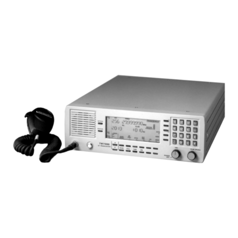
The RT7000 transceiver provides a complete range of voice and data operation
over the entire 1.6 to 30 MHz HF spectrum. The RT7000 is microprocessor-
controlled and features a state-of-the-art DDS-based synthesizer. An LCD
provides channel and frequency data, feedback on other front panel control
functions, BITE information and order-wire text messages.
The RT7000 has continuous tuning and up to 1000 memory channels that can
be arranged in multiple scan groups. It has simplex and half-duplex capability
and a full alphanumeric keypad for frequency or text entry. The RT7000 is
packaged in a rugged, waterproof housing designed to withstand harsh
environments.
This manual describes the RT7000 including its installation, operation and
organizational maintenance features. For complete technical information, refer
to the RT7000 HF Transceiver technical manual (RT7000-MS).
Description of Equipment
The two basic models of the RT7000 are the RT7000-12 (+12 Vdc primary
power) and the RT7000-28 (+28 Vdc primary power). Both models include the
basic receiver/transmitter and an accessory kit. The accessory kit contains a DC
power cable (C991556), spare DC fuses (550012 for +12 Vdc and 550022 for
+28 Vdc) and this manual.

1: Introduction
1-2 RT7000-MSOP
The RT7000-12 is powered from any DC source providing +13.8V at a
maximum of 25A. Good performance is achieved when the input voltage is in
the range of 11 to 15.5V. The RT7000-28 is powered from any DC source
providing +28 Vdc at a maximum of 15A (a range of 22 to 30 Vdc).
The RT7000 is used with broadband 50 ohm antennas or narrowband antennas
in conjunction with an automatic antenna tuner.
The RT7000 can be programmed and operated from its front panel or from an
external computer (if the ALE option is installed) utilizing a wide variety of
interface standards including RS232, 422 and 485.
Audio accessories available for use with the RT7000 include a heavy-duty
hand microphone, dynamic desk microphone, Morse key and headphones.
Technical Specifications
Note: Specifications are subject to change without notice or obligation.
Characteristic Specification
General
Frequency range 1.6 to 30 MHz (TX); 100 Hz to 30 MHz (RX);
10 Hz channel spacing
Preset channels 256 standard, 1000 optional
Scanning Multiple scan groups, operator-selectable scan rates
Channel
programming
From front panel or remotely via computer or
dedicated remote control console
Frequency stability 0.5 ppm
Modes USB, LSB, CW, AME; simplex or half-duplex
Input power
requirements
11 to 16 Vdc (+12 Vdc models);
20 to 32 Vdc (+28 Vdc models)
Input power
protection
Reverse polarity, transient and under/over-voltage
Antenna port 50 ohms, type N connector
Antennas 50 ohms or automatic antenna tuner (RAT7000B,
RAT1000C) for narrowband antennas
Interface Control: two RS32 COM ports; compatible with EIA
RS422/423/485 with option.
Audio: 600 ohms, balanced and isolated
Mechanical, Environmental
Size (H x W x D) 6 in. x 14 in. x 18 in.
(15.2 cm x 35.6 cm x 45.7 cm)
Weight 35 lbs. (15.9 kg)

1: Introduction
RT7000-MSOP 1-3
RT7000 Variations
This manual provides information necessary to operate any variation of the
RT7000. Options described here may not be available on your transceiver. For
more information about these variations, contact Datron.
RT7000C Designed for computer control. A blank front panel replaces
the standard front panel.
RT7000E Designed for extended control use. A line driver panel replaces
the standard front panel. It is used with the RT7201E control
head for remote operation up to 15m (50 ft.).
RT7000PP Allows the addition of the RT5830 Pre/Postselector and
RT5830INST installation kit for co-sited operation.
Note: The RT5830 requires the RT7000 to have both the
RT7000PP and the RT5830INST. The RT7000 is not field
upgradeable to an RT7000PP.
RT7000RF Designed for long distance remote-only use beyond 2 km. A
blank front panel replaces the standard front panel. An internal
modem card (7000RF) is installed. For full function FSK
remote control, use with the RT7201F.
Cooling Rear panel heatsink;
RT7000FAN-1 fan kit (optional)
Temperature -30°C to +60°C, operating
Shock, vibration,
humidly, fungus,
sand, dirt
Per MIL-STD-810D, MIL-STD-810E and
MIL-STD-810F
Transmitter
RF Power output 125W PEP, 100W average
Duty cycle Continuous service, all modes;
programmable - 3 levels
Harmonics -60 dB (2 to 30 MHz) nominally
Receiver
Sensitivity 10 dB SINAD for 0.5µV input (2 to 30 MHz)
Attenuator +20 dB, operator switchable
Audio 5W into 4 ohm; 0 dBm into 600 ohms
Characteristic Specification

1: Introduction
1-4 RT7000-MSOP
RT7000RI Designed for remote-only use up to 2 km. The standard front
panel is replaced with a blank front panel. An internal modem
card (7000RI) is installed. For full function, real time, ISDN
remote control, use with the RT7201I.
RT7000RX Receiver only. It includes the full receiver functions of the
RT7000, excluding transmit features.
RT7000TX Transmitter only. It includes the full transmitter functions of
the RT7000, excluding receiver features.
Internal Options
Several internal options are available for the RT7000.
7000ACH Additional channels. Increases operational channel capacity
to 1000.
7000ALE FED-STD-1045 compatible adaptive system. Provides
complete 1045 capability, including link quality analysis,
auto-linking, sounding, and orderwire message transmission
and reception.
7000CLK Internal clock keeps and displays the time and includes
alarm features.
7000CW Narrowband filter with 500 Hz bandwidth for CW
operation.
7000ENCR High-level voice encryptor uses enhanced domain transform
(EDT) ciphering techniques providing long-term security.
7000FALC Fast ALC loop for use with linear amplifiers that utilize
peak detecting ALC like the TW1000D.
7000HS High stability reference oscillator allows 0.1 parts per
million frequency stability.
7000HS-FALC High stability reference oscillator and fast ALC loop
operation.
7000NB Impulse-type noise blanker used in high-noise
environments.
7000RCDR Combines receive and transmit audio and routes them to
Accessory 2.
7000RF Internal modem allows remote contact from the TW7201F
FSK controller.

1: Introduction
RT7000-MSOP 1-5
7000RI Internal modem allows remote contact from the TW7201I
ISDN controller.
7000RS Modem interface board configures a second serial port
(RS422/485) to provide data protocol for external control of
the radio through a computer. This is in addition to the
standard RS232 interface.
7000TC Digital selective calling system plus automatic path
evaluation. Combines all functions of Transcall, Selcall, and
TransAdapt.
7000VEM DSP-based voice enhancement provides superior voice
recognition and signal-quality improvement in noisy
environments.
7000WB1 Wideband data filter providing 300 to 3300 Hz with tailored
group delay characteristics for data operation.
RT7000AIRSELCALL
Operating with N-1304A (or equivalent) SELCAL devices
and Datron power amplifiers, it adds a secondary control
line to the radio and allows use of the ICAO-mandated
ground-to-air SELCAL 3-tone system.
Conventions
Bold type is used to denote all items that appear in the display area and for any
button, knob or connector used on the front or rear panel. For example:
• Press Cand 041 and E.
Display: CH FREQ
041 13.330,000 MHz
Rx
• Press ALPHA and 17.
• Press STATUS.
Referenced Manuals
• RT7000-MS Transceiver technical manual
• 7000ALE-MSOP ALE Radio Control operator manual
• 7000ENCR-MSOP High-Level Encryption operator manual
• RT7201I-MS ISDN Remote Control operator/technical manual
• RT7201F-MS FSK Remote Control operator/technical manual
• RC2-MSOP Radio Control 2 Software operator manual


RT7000-MSOP 2-1
CHAPTER 2
INSTALLATION
This section contains information necessary to install the RT7000 in its
operating environment. Power, antenna, and accessory connections are
discussed. System diagrams are provided to show the proper connections to a
variety of accessories.
Unpacking and Inspection
When unpacking the RT7000, carefully remove the equipment from its
container and inspect it for any possible damage. If anything is damaged, notify
Datron. Check the equipment against the packing list. Save the original
container and packing materials for storage or reshipping purposes.
Location Considerations
The RT7000 can be deployed successfully in various locations, in a number of
different configurations, depending on whether remote or extended control is
used. Information in this section pertains to the main body of the RT7000,
whether it is controlled locally or from a remote site.
Fixed Station Unless otherwise specified when ordered, the RT7000 is shipped ready for
operation. It is also available for mounting in a rack, provided the appropriate
rack kit is ordered.
Make sure the temperature at the location is within the specified range, and that
there is adequate ventilation around the rear of the RT7000 to allow for air flow.
The RT7000 has a rear panel heat sink to dissipate heat that is generated from
the power amplifier during transmission. The RT7000FAN-1 external option
provides continuous cooling when conditions require heavy use.
To prevent unwanted noise, locate the RT7000 as far away as possible from
electrostatic and magnetic field-generating equipment.
When attaching external cables to the RT7000, allow for sufficient slack in the
cables. This prevents damage from sharp bends and ensures easy disconnection.
Vehicular or
Marine
Use the mobile mount to mount the RT7000. It may be necessary to fabricate
special supplementary brackets to complement a particular vehicle or shipboard
location. Datron offers rack, mobile, and shock mount kits for the RT7000,
suitable for most installations.

2: Installation
2-2 RT7000-MSOP
Front Panel Connections
Two 6-pin microphone connectors on the front panel are wired in parallel and
suitable for use by various audio accessories.
Low-level audio accessories for use with the RT7000 include the following:
The input impedance is a nominal 150 ohm. Most dynamic, ceramic or
magnetic microphones operate satisfactorily with the RT7000. All Datron-
supplied audio accessories have the correct mating connector on them. To use
other low-level audio accessories, obtain the correct mating connector from
Datron.
Figure 2-1. Front Panel Connections
Part Description
MRR Heavy duty hand microphone
MHS U.S. MIL-STYLE H-189/U handset
KYR Morse key
HPR Headphones
H3M Headphones with boom microphone
H-250/U Non-repairable version of MHS
Audio
Connectors

2: Installation
RT7000-MSOP 2-3
Rear Panel Connections
The rear panel of the RT7000 is made of die cast aluminum and is attached to
the rear side panels by 4 hex head bolts. The heat sink maintains the
temperature within operational specifications eliminating the need for an
internal cooling fan. It fills most of the rear panel area leaving room for the
fan power connector and optional pre/postselector RF connections.
The accessory, remote control and RF connections are wired to the Interface/
Power supply board.
Power to the
RT7000
Input power for the RT7000-12 is nominally 13.8 Vdc, with a maximum
current requirement of 25A. The recommended operational voltage range of
the transceiver is 11 to 15.5 Vdc. The RT7000-28 requires +28 Vdc at a
maximum of 15A (range of 22-30 Vdc). The DC input connector on the rear
panel is a 2 pin, 30A circular receptacle that has a square mounting flange
with 2 male pins. The mating plug is attached to the input DC power cable
(C991556). This cable, supplied with the RT7000, has a convenient
connection to a variety of DC power sources. For specific connections, refer
to the "Power Cabling Accessories" figure on page 2-6.
The DC power connection between the RT7000 and its power source should
be as short as possible. If a Datron power cable is not available, use a 14 AWG
cable for runs up to 3 feet, a 12 AWG cable for runs to 9 feet, or a 10 AWG
cable for longer runs.
Figure 2-2. Rear Panel Connections
DC
In
p
ut
Accessory
1
Accessory
2
Accessory
3
Remote
Control
Fuse Antenna
Fa
n

2: Installation
2-4 RT7000-MSOP
Two DC power supplies are available from Datron when a +12 or +28 Vdc
primary power source is not available:
UPF7000A-12 Heavy duty power supply permits continuous duty opera-
tion. Runs off 84-240 VAC, 50/60 Hz and requires a
C991511 cable.
UPF7000A-28 Heavy duty power supply permits continuous duty opera-
tion. Runs off 84-240 VAC, 50/60 Hz and requires a
C991511 cable.
The waterproof fuse holder (pin 630005) on the rear panel contains either a
25A (12V), 3-AG fuse or 15A (28V), 3-AG fuse.
Antenna
Connection
The RT7000 is designed to work into a 50 ohm RF impedance. The output RF
antenna connector is a type N connector. Broadband antennas and dipoles can
be connected directly to this output, while high-power amplifiers and antenna
tuners use specially-designed Datron cables. For specific connections, refer to
the "RF Cabling Accessories" figure on page 2-7.
External Fan
Connection
The external fan cooling kit (RT7000FAN-1) mounts on the back of the
heatsink and is mandatory for light duty cycle HF data applications.
Accessory
Connections
A variety of external accessories are available from Datron for use with the
RT7000. For some of these accessories and their control cabling, refer to the
"Control Cabling Accessories" figure on page 2-8. For more information on
any individual accessory, refer to the manual for that piece of equipment.
There are three accessory connectors on the rear panel, each with different pin
assignments. If multiple accessories are required that share one or more of the
accessory connectors, an external accessory combiner box (RT7000IOX) can
be attached to any of these connectors. Each of the three connectors on the
rear panel is a circular MIL-C with 26 pins. For the location of these
connectors, refer to the "Rear Panel Connections" figure on page 2-3.
External
Encryption
Using the 7000ENCR option, the RT7000 allows provision for an embedded
encryption board. External encryption can also be used with the RT7000 and
connected to Accessory 1 or Accessory 2.
Telephone
Couplers
Telephone couplers like the RT5810 or RT5850 use either Accessory 1 or
Accessory 2.
EIA Data
Interface
Standards
The RT7000 interfaces with a variety of data communications equipment
(DCE) or data terminal equipment (DTE) using EIA standards RS232, RS422
or RS485. Accessory 1 is configured to provide the standard I/O port (COM1)
for these interfaces. The RS232 protocol is standard; all others are optional. It
is necessary to order the 7000RS option and to specify the required protocol
so the appropriate interface chip is inserted into the processor.

2: Installation
RT7000-MSOP 2-5
If the 7000RS option is installed, the COM1TXD and COM2RXD becomes a
2-wire bidirectional RS422/485 interface.
A 3-wire RS232 interface is also available on Accessory 2.
Automatic
Antenna
Tuners
The RT7000 interfaces with the complete line of Datron automatic antenna
tuners. This includes the older AT/RAT100 and RAT1000 as well as the newer
AT/RAT7000B and RAT1000B.
The AT/RAT100 and RAT1000A and RAT1000C connect to Accessory 2. The
AT/RAT7000 uses Accessory 3.
Data Terminal
Interface
The RT7000 interfaces with its own line of data terminals or to other external
units using Accessories 1 and 2.
External
Printers
A standard parallel printer connects to Accessory 1 to obtain a hard copy of
text messages stored in the RT7000.
ALE/Transcall/
Selcall Alarm
The external ALE/Transcall/Selcall alarm driver is available on Accessory 2.
External
Speaker
An external speaker attaches to the RT7000 at Accessory 2.
External
High-Power
Amplifiers
The RT7000 interfaces with all existing Datron high-power RF booster
amplifiers using Accessory 3.

2: Installation
2-6 RT7000-MSOP
Figure 2-3. Power Cabling Accessories
DT110DT5300DT9400
110/220V 50/60Hz
Power Source
DC Supply
(provided with
DT-series
computers
)
IN OUT
F1 F2 GND
RF
IN
RF
OUT
RA1000D
220V 50/60Hz
Power Source
RT5810
115/230 VAC
50/60Hz
Power Source
+12 Vdc
Power Source
RT5850
+12Vdc
Power Source
RT7000-12/28
DC
INPUT FUSE REM ACC3 ACC2 ACC1
ANTENNA
110/220 50/60Hz
Power Source
C991511
UPF7000-12/28
C991556
DC Power
Source
10-30 Vdc
C992042
RT7201
RA400
RF OUTPUT RF INPUT
J2
DC IN DC OUT
J3 J4 J5 J6
ATU
CONTROL
IN
ATU
CONTROL
OUT
AMP
CONTROL
J1
J7
110/220 50/60Hz
Power Source
DC Power
Source
ACC1 REMOTE
AC INPUT DC INPUT
C992034 US 110
C992139 US 220
C992034 C991557
UPF500
+_
This manual suits for next models
1
Table of contents
Other Datron Transceiver manuals
