David Rolo TWIN PEAKS TREMOLO User manual
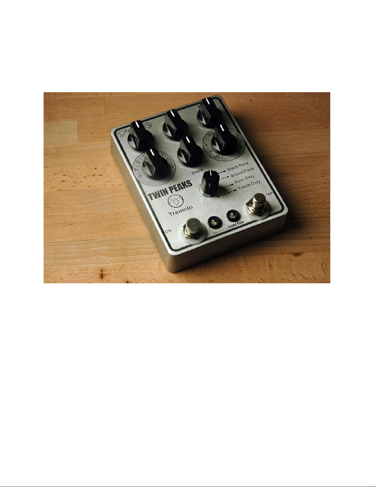
TWIN PEAKS TREMOLO
Build Guide for v2.1
Revision 2.1
David Rolo 2014
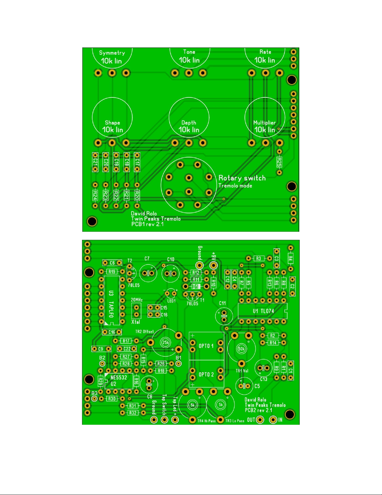
The build consists of 2 boards that were designed to fit in a BB enclosure with top mounted open jacks. PCB1 holds the
pcb mounted pots and rotary switch. PCB2 holds the main circuit.
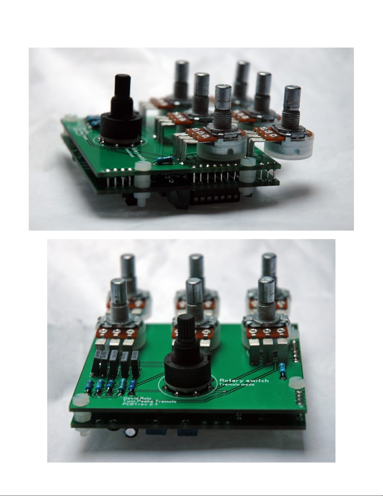
The 2 boards are connected together like this:
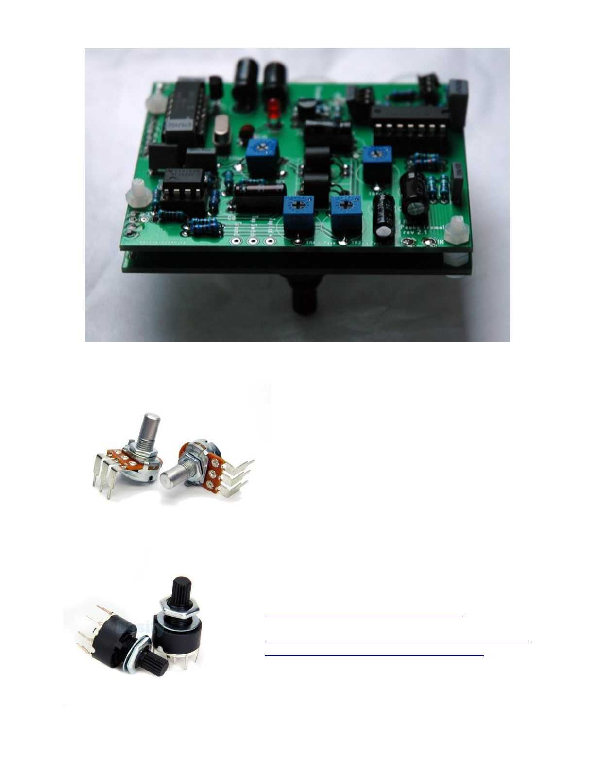
The pots best suited are Alpha 16mm Right-angle PCB mount Pots:
And one mini rotary 2P4T switch like these:
Of course you can use other parts and not mount them on the PCB. Then you will probably need a bigger enclosure.
They can be ordered in batches from different places like:
http://www.befr.ebay.be/itm/300881322642
http://www.aliexpress.com/item/Free-Shipping-20-x-Plastic-
Band-Switch-2P4T-Rotary-Switch/996781872.html
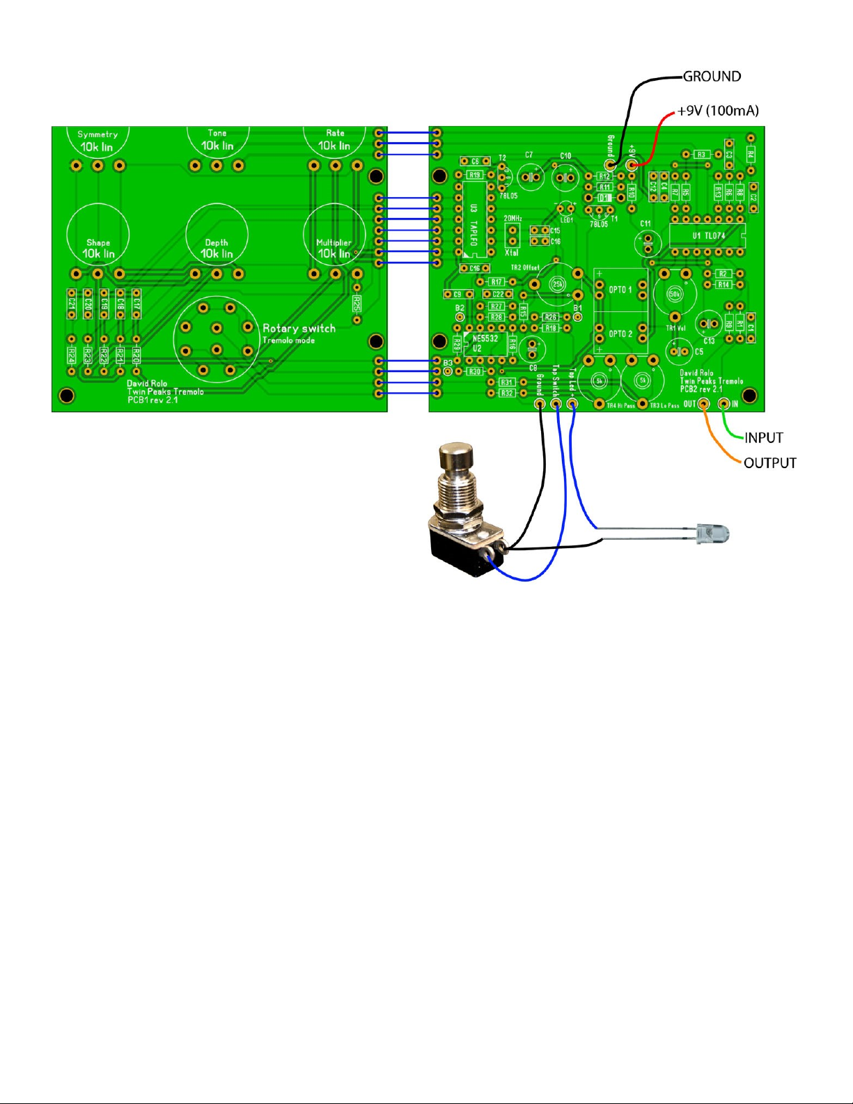
Here is a wiring diagram:
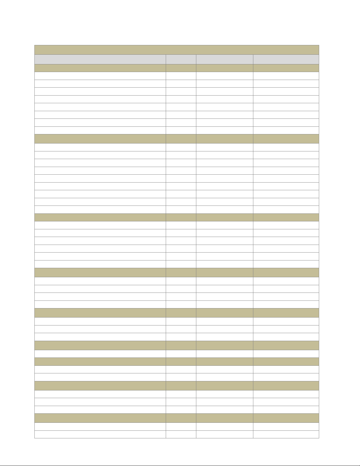
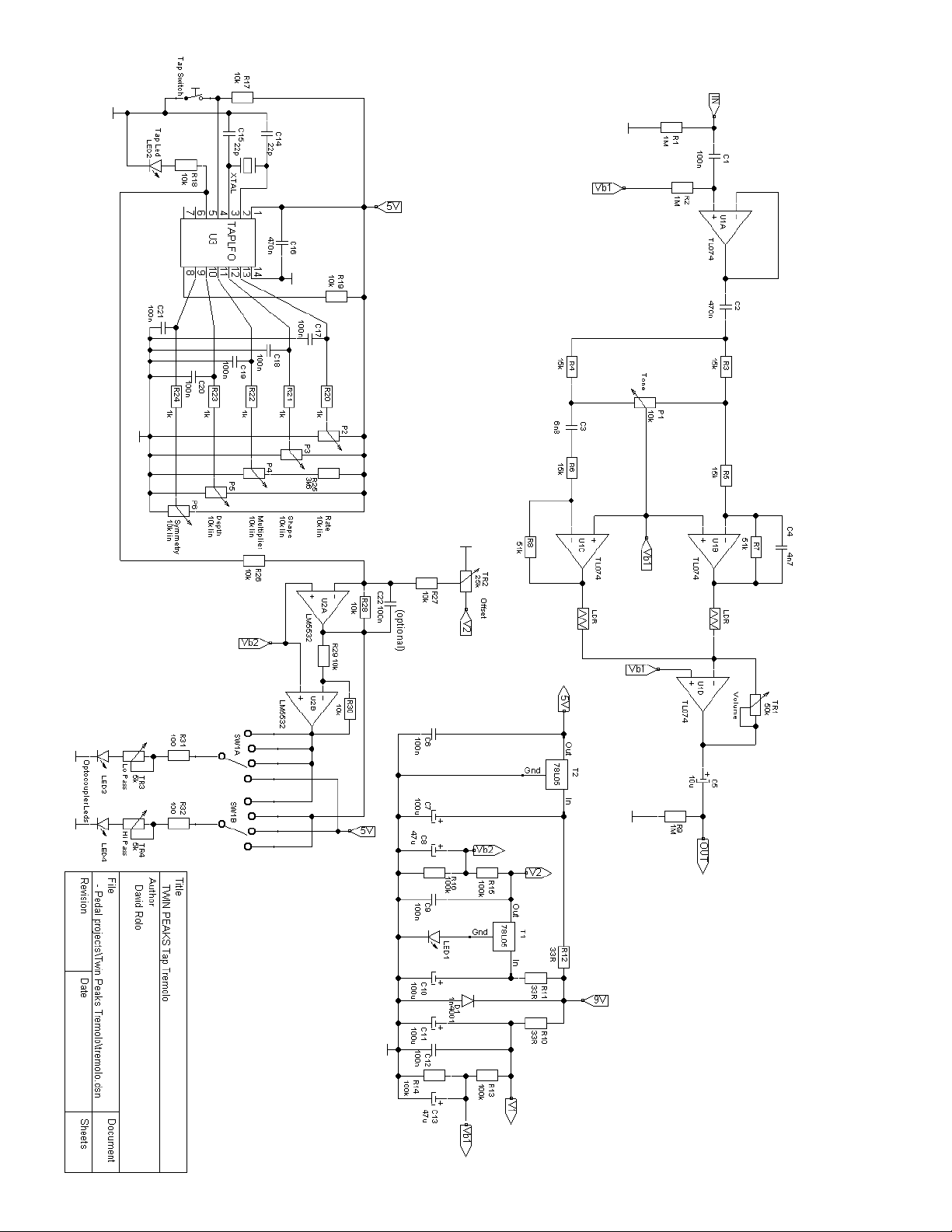
Twin Peaks Tremolo Bill of Materials
Reference
Quantity
Name
Description
CAPS
C14,C15
2
22p
Capacitor
C4
1
4n7
Capacitor
C3
1
6n8
Capacitor
C1,C12,C17,C18,C19,C20,C21,C22,C6,C9
10
100n
Capacitor
C16,C2
2
470n
Capacitor
C5
1
10u
Capacitor Electrolytic
C13,C8
2
47u
Capacitor Electrolytic
C10,C11,C7
3
100u
Capacitor Electrolytic
RESISTORS
R10,R11,R12
3
33R
Resistor
R31,R32
2
100R
Resistor
R20,R21,R22,R23,R24
5
1k
Resistor
R25
1
3k6
Resistor
R17,R18,R19,R26,R27,R28,R29,R30
8
10k
Resistor
R3,R4,R5,R6
4
15k
Resistor
R7,R8
2
51k
Resistor
R13,R14,R15,R16
4
100k
Resistor
R1,R2,R9
3
1M
Resistor
POTS
P1
1
10k lin
Tone
P2
1
10k lin
Rate
P3
1
10k lin
Shape
P4
1
10k lin
Multiplier
P5
1
10k lin
Depth
P6
1
10k lin
Symmetry
TRIMPOTS
TR3
1
5k
Lo Pass
TR4
1
5k
Hi Pass
TR2
1
25k
Offset
TR1
1
50k
Volume
IC's
U1
1
TL074
OpAmp
U2
1
NE5532
OpAmp
U3
1
TAPLFO
Microchip
VOLTAGE REGULATORS
T1,T2
2
78L05
Fixed Voltage Reg.
DIODES/LEDS
D1
1
1n4001
Diode
LED1,LED2,Bypass LED
3
LED
Light Emitting Diode
SWITCHES
SW1A,SW1B
1
2P4T
Four position Rotary
Tap Switch
1
Momentary Switch
Normally Off
Bypass Switch
1
3PDT
OTHER
XTAL
1
20MHz
Crystal Oscillator
VTL5C1/NSL32
2
VTL5C1/NSL32
Optocoupler
Here are the steps I would recommend to assemble the boards:
1) Populate the boards with all parts, starting with the smallest to the tallest. Solder in the pots and rotary switch
last.
Notes:
Use sockets for the IC’s, at least for the TAPLFO
Depending on the kind of caps you use, you may need to lay down your electrolytics flat on the board to
gain space. I made sure to leave enough space on the board to accommodate the lying caps.
R18 is the current limiting resistor for the Tempo indicating LED. The indicated value of 10k is what I am
using with white super-bright LED’s. Choose the value that will be best for your particular LED. I would
recommend a super-bright as they will draw less current and reduce the chances of inducing ticking.
C22 is used to smooth out the sharp corners of the LFO signal and remove some spikes that can produce
audible clicks especially with sharper edged wave shapes. You might not necessarily need it. It depends on
your particular Optocoupler and whether you like the signal to be chopped real hard or not. I suggest
socketing that cap, trying without it first and then start with a low value like 20n until you find a value that
removes the tick but does not round off the square wave too much.
C3 and C4 define the High Pass and Low pass cut off frequency. If my calculations are right, with the values
indicated in this document, the Low pass cuts at 664.3 Hz and the Hi pass at 780.6 Hz. You can of course
experiment with other values.
LED1 is there to increase the output of the voltage regulator (5V + the Forward voltage of the LED). Try to
find a LED with no more than 2V FWD voltage to make sure the voltage regulator still has enough drop out
voltage to operate correctly. Note: the silkscreen shows the flat side the wrong way around. Follow the –
and + signs for correct orientation.
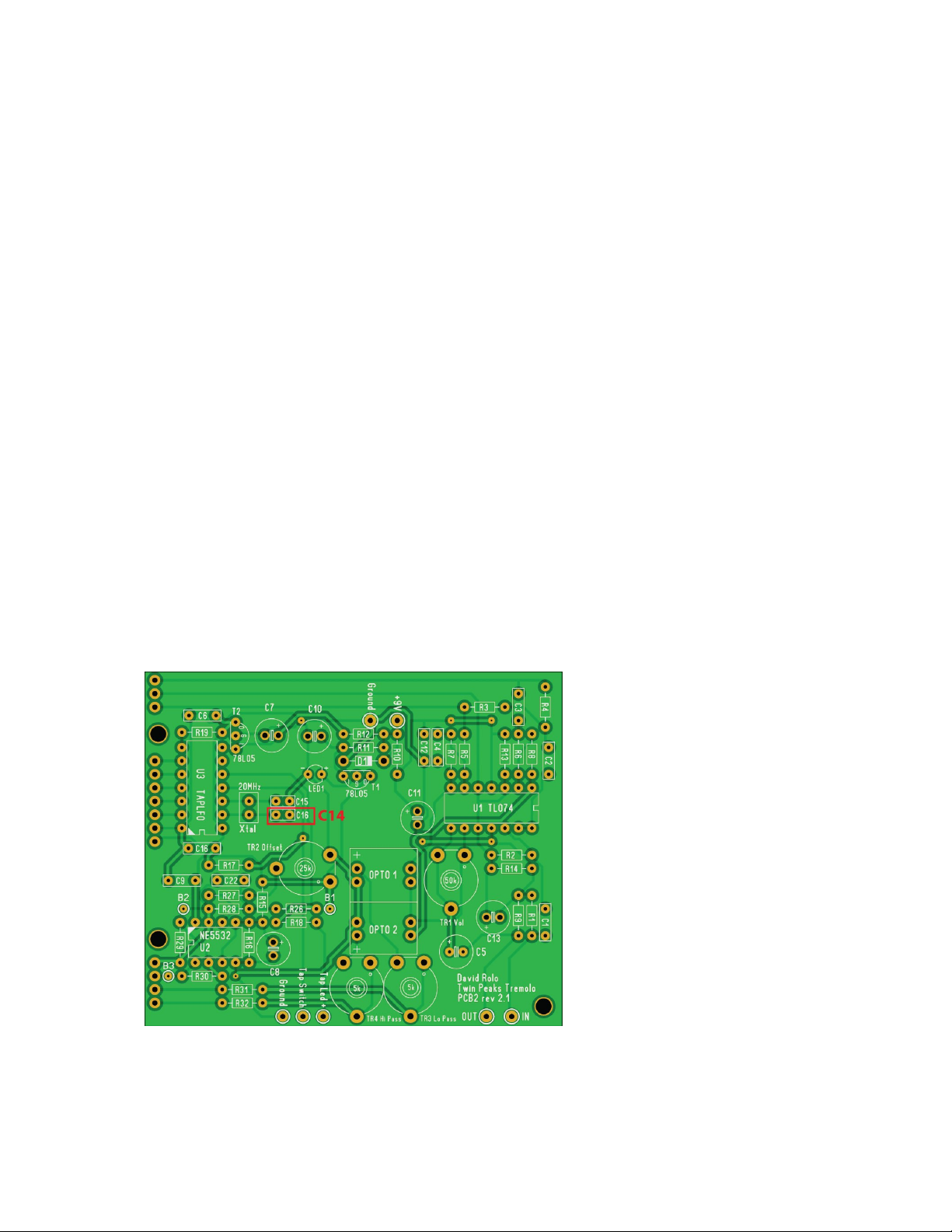
C14 –one of the 22p caps next to the Crystal are labeled wrong. On the PCB it shows C16, when it should be
C14:
Once soldered, cut the components’ leads as short as possible to minimize the space needed between the
two boards

2) When you have finished populating the boards, solder all needed outboard wires (not the ones connecting the 2
boards together) already in place leaving enough length to connect to their destination later on.
3) Fit the 2 boards back to back with a piece of cardboard or other insulator between them.
Don’t use anything too thick but also not too thin that component leads could poke through and cause a short.
There are 3 holes where you can fit screws (M2.5 or M3, preferably plastic) that will secure the boards together
with spacers between them.
4) Now connect each opposing hole of the 2 PCB’s together with some wire. I prefer solid core wire but twisted
stranded wire will be OK too. Just watch out for loose strands that could cause a short.
5) Now you can fit the boards inside your enclosure and connect the outboard wires to their corresponding points,
the bypass and Tap switches, LED’s, jacks etc
Now that you have finished assembling the pedal, you can bias it:
1) Turn the DEPTH pot fully counterclockwise, SYMMETRY and TONE in middle position
2) Set T3 and T4 fully counterclockwise
3) Start by measuring the supply voltage at bias point B1
4) Adjust the Offset trimpot T2 until you get the same voltage (about half of the voltage of B1) on bias points B2
and B3. This action will center the LFO signal (originally 0-5V) around the bias voltage of U2.
5) Now adjust T3 and T4 to have a good balance between bass and treble. As you turn clockwise, the optocoupler
gets more current and the signal gets louder. But increasing the current also increases the chance of getting
audible clicks, especially with sharp wave shapes. So it’s best to be conservative and compensate for the volume
with T1.
6) Adjust the volume trim pot T1 to have the same level between effect OFF and effect ON (or any level you like).
That’s it! Now trem’ away ;-)
Controls:
Rotating from CCW to CW, the rotary switch selects the tremolo modes:
Bass and treble modulated in phase (normal tremolo)
Bass and treble modulated out of phase (Harmonic tremolo)
Bass modulation only, with fix treble
Treble modulation only, with fix bass
Pots:
Tone : adjusts the balance between the bass and treble portions. Turn it fully CCW and only the bass
comes out. Turn it fully CW and you get only treble. In the middle you get both. If you turn down the
depth completely you can use the tone knob as a sort of EQ
Depth: Allows setting the depth of the modulation
Rate: Sets the speed of the modulation
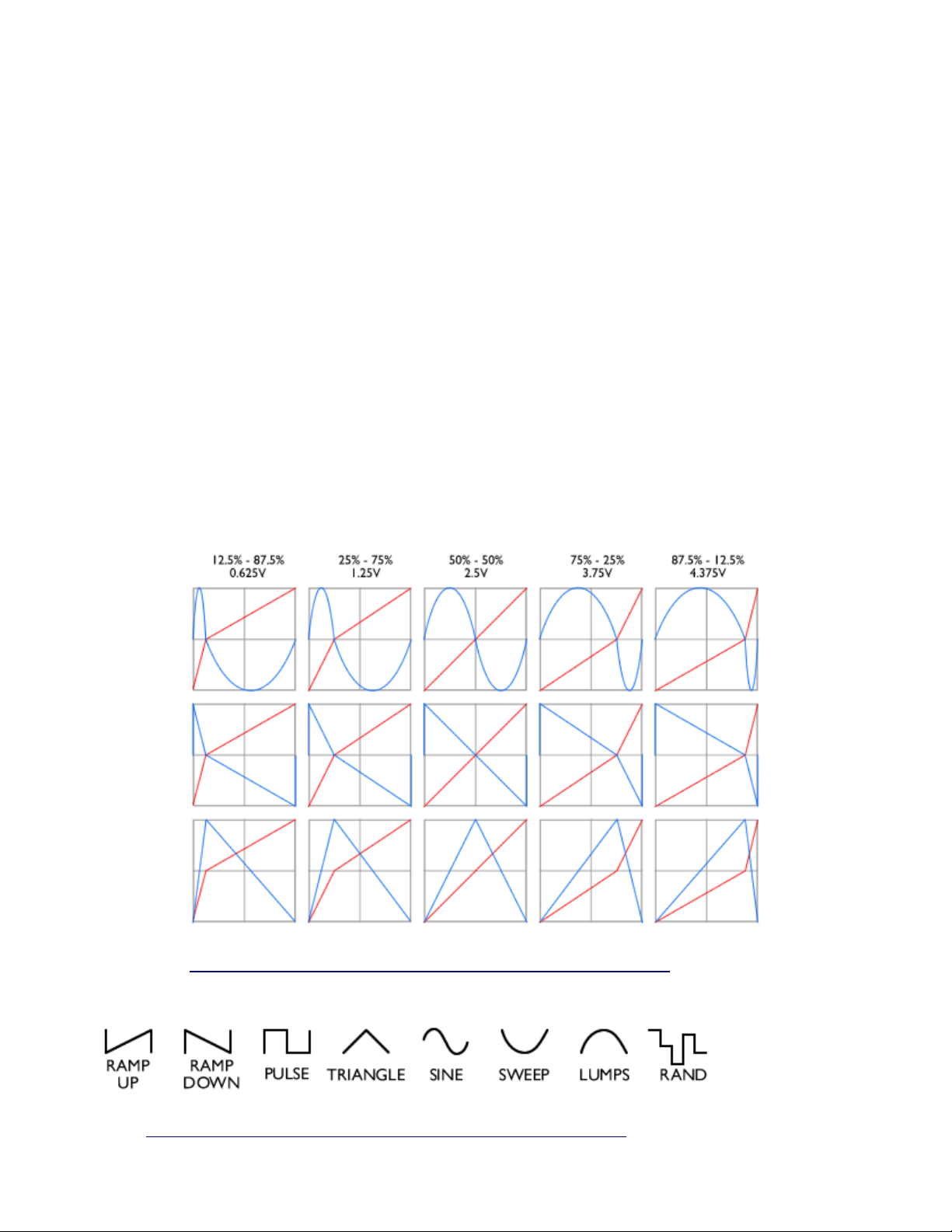
Symmetry: Allows changing the ratio between the upper and lower wave of the LFO signal For
example, when using the square wave, you can set whether the “off” or the “on” periods are the
longest.
This diagram shows the effect of the symmetry pot on some wave shapes:
Source: http://www.electricdruid.net/datasheets/TAPLFO2Datasheet.pdf
Shape: This knob allows selecting one of the 8 available modulation wave shapes:
Source: http://www.electricdruid.net/datasheets/TAPLFO2Datasheet.pdf

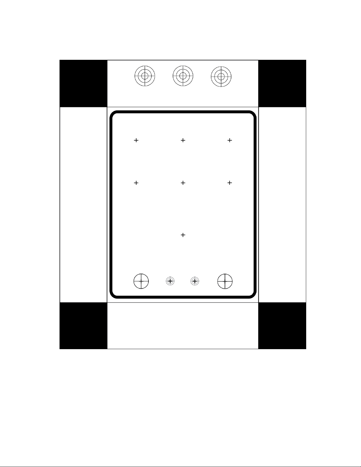
This is a drill template I have been using but take your own measurements to make sure everything fits (before
committing to drilling your box … ;-)


