DAVID DigaStudio User manual

DigaStudio
DigA
S

DigaStudio: Functional Specification Page 2 of 14
Content
1 Overview........................................................... 3
1.1 Philosophy ........................................................................................3
1.2 Housing .............................................................................................4
1.2.1 Control pad.................................................................................................................4
1.2.2 Interface unit .............................................................................................................. 4
2 Functionality ..................................................... 5
2.1 Audio input........................................................................................5
2.2 Channel functions............................................................................ 6
2.2.1 Source selection / channel assignment.................................................................. 6
2.2.2 Limiter / clipping display...........................................................................................6
2.2.3 Equalizer / filter..........................................................................................................6
2.2.4 Channel Mode............................................................................................................6
2.2.5 Inserts / effects...........................................................................................................7
2.2.6 Fader / level meter..................................................................................................... 7
2.2.7 Mute button and talk-back........................................................................................7
2.3 Summing busses..............................................................................8
2.4 Outputs..............................................................................................8
2.4.1 Monitor matrix............................................................................................................9
2.5 GPI / external level meters...............................................................9
2.6 DigaStudio Pro..................................................................................9
2.6.1 Channel functions .....................................................................................................9
2.6.2 Microphone inputs................................................................................................... 10
2.6.3 Digital audio inputs .................................................................................................10
2.6.4 Digital audio outputs...............................................................................................10
3 Edit Controller..................................................10
4 PC control ........................................................11
5 Accessories .....................................................12
6 Technical Data..................................................13
All of the specifications contained in this
document can change without notice
Status as of: 14.04.99

DigaStudio: Functional Specification Page 3 of 14
1Overview
DigaStudio is an audio and control interface for users of PC audio workstations who do not have a
studio environment available. The product is designed for normal office environments and users who
are not specifically trained as audio technicians.
DigaStudio consists of an interface and signal-processing module and a separate flat control-pad. The
control-pad is connected by means of a single cable to the interface module, to which all audio and
control lines are connected. It is designed to avoid looking like a technician's workbench with masses
of cable on the desk. The entire system provides an integrated studio with user-friendly interface at
„your“ workstation, containing the following functionality:
•Input matrix: connection and selection of a variety of audio sources
•Mixer: typical mixing and editing functionality
•Edit Controller: control panel for the editing software
The following typical tasks are possible:
•Recording from microphone or any other connected source
•Recording of interviews with multiple partners
•Recording of telephone interviews (via telephone or ISDN codec)
•Production of audio clips with simple mixing of pre-produced elements and live sources
•Playback of live events with microphone and PC recording or other sources
•Transfer of edited clips to main studio or between various media
The product is available in two versions: DigaStudio und DigaStudio Pro. The additional functions of
the pro version are explained in section 2.6 DigaStudio Pro.
1.1 Philosophy
•Ease-of-use
•Simple implementation, therefore mainly analogue inputs and outputs
•Internal digital signal processing
•High number of external devices connectable through various audio connectors
•Very high input dynamic range (24-bit A/D) so that overdrive problems are not
encountered with unskilled users
Use of the system is divided into those important operations which are accessed directly via the control
pad, and those functions which can only be accessed by means of software on the PC. The latest
settings are stored in the processing unit so that it can perform its basic functions without being
connected to the PC.
DigaStudio's parameters can be made user-specific by means of the PC, so that user-profiles can
move with the user to various workstations. Specific settings, such as the filter parameters, can be
stored on a per-user basis and then activated in the signal processing unit as the user logs-in.
DigaStudio: Functional Specification Page 4 of 14
1.2 Housing
DigaStudio consists of a 19" (2HE) interface and signal processing unit and a flat control pad. The
control pad is connected to the interface unit by means of a single cable. The length of the cable is
unrestricted (with respect to typical studio environments).
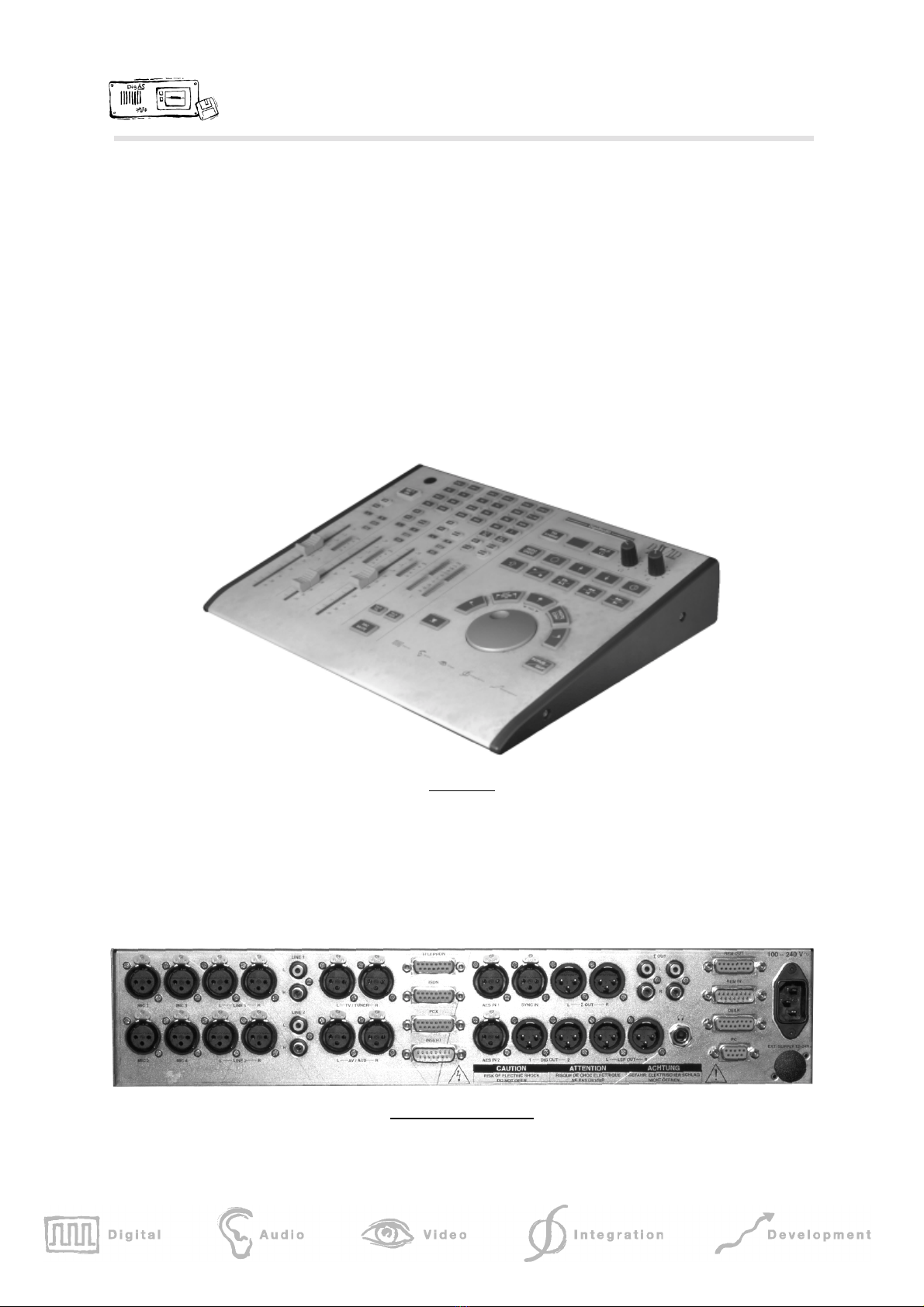
1.2.1 Control pad
•Flat desktop case
•A single-cable connection to the interface unit
•Control elements for the functions described below
•Pre-drilled for optional gooseneck microphone
Control Pad
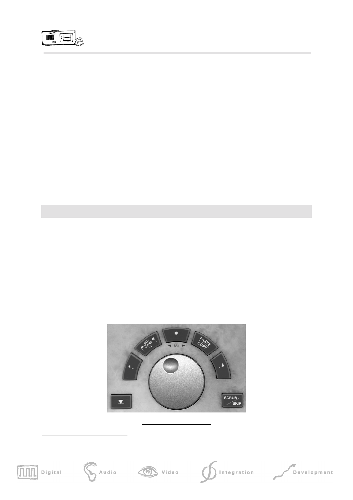
1.2.2 Interface unit
•19“ (2HE)
•Power-supply (internal) for all supply voltages w/ power switch on the front panel
•Connectors for all incoming and outgoing audio and control signals on the rear panel
Rear view of interface unit

DigaStudio: Functional Specification Page 5 of 14
2Functionality
2.1 Audio input
The control pad contains an input matrix which allows the connection of the following sources:
•2 x MIC (microphone)
•2 x LINE
•1 x TV / Tuner
•1 x AV / AUX
•1 x AWS (PCX card)
•1 x TEL (external telephone hybrid)
•1 x ISDN (external ISDN codec)
•1 x INSERT
All inputs have adjustable input-level controllers which can be controlled via the PC software so that
the signal level can be adjusted individually prior to the A/D convertion.
Both MIC inputs (MIC1 / MIC2) are symmetrical mono inputs using XLR connectors with input
transformer. 48V phantom power is switchable. Input sensitivity can be adjusted within 0,5 dB steps
from -20..-80 dBu.
Both LINE inputs are configured as stereo sources and can handle symmetrical and asymmetrical
signals. There are 2 XLR jacks for the symmetrical configuration and 2 cinch jacks each for the
asymmetrical. The symmetrical and asymmetrical inputs are passively mixed but are actively de-
coupled to allow concurrent use.
TV / TUNER and AV / AUX inputs are each configured as stereo sources, each with 2 XLR
connectors.
The audio workstation input (AWS / PCX) is also configured as a symmetrical stereo source (analog),
but uses a 15-pin sub-D connector for directly connecting to a PCX card (including return path to audio
input of PCX board).
The TELEPHONE input is for connecting an analog telephone hybrid and is configured as a mono
source. It uses a 15pin sub-D connector and contains both the return channel and external control
signal for activation.
For connecting an ISDN codec a separate symmetrical stereo input is provided, which also uses a sub-
D connector connector (including return signal and control signal as well).
The INSERT input is provided so that effects devices or signal processors (e.g. voice processors) can
be switched in. It is configured as a symmetrical stereo input with a 15-pin sub-D connector. The
connector also contains the necessary INSERT SEND output.
All of the symmetrical inputs are electronically balanced, with the exception of the two transformer
symmetrical microphone inputs. The input sensitivity can be set in 0.5 dB steps between +24..-10 dBu.

DigaStudio: Functional Specification Page 6 of 14
2.2 Channel functions
The basic version of the DigaStudio contains 3 mixing channels, which are described below.
2.2.1 Source selection / channel assignment
Channel 1 can be assigned to MIC1 or MIC2, whereas channels 2 and 3 can be
assigned to any source. There are 8 source selection buttons associated with
channel paths 2 and 3. The channel selection is "1 from N", so that one source
can only be assigned to one channel. The currently selected input source is
illuminated. The assignment of the input sources to the output buttons can be
freely selected. The labels for the input selection buttons can be customized by
means of a special adhesive foil.
2.2.2 Limiter / clipping display
Each channel has its own adjustable limiter which can be switched on or off by means of an illuminated
button. The limiter can either be assigned to the individual channels or the sums. The configuration is
controlled from the PC software.
To prevent the input A/D converter being over-driven a clipping display is provided (special function
within the level bar-graph).
2.2.3 Equalizer / filter
Each channel has its own 3-band equalizer with the following characteristics:
•low-band shelf-type filter
•parametric mid-frequencies
•high-band shelf-type filter
The microphone inputs have additional switchable high-pass filters available.
The equalizer and filter can only be configured and activated from the PC. An active equalizer or filter
is indicated in the channel path by an LED (EQU). The frequency response can be displayed
graphically on the screen.
2.2.4 Channel Mode
Channel 1 is exclusively assigned for mono (MIC1). Channels 2 + 3 have a Mono/stereo button; the
current condition is indicated through the key lamp.
The PC software allows the user to configure the processing of left and right channel; the current
setting is displayed through the L and R LEDs:

DigaStudio: Functional Specification Page 7 of 14
LED
LLED
RMode
off off normal
on off left channel only
off on right channel only
on on left right swapped
Panning is available in mono mode, in stereo mode balance control is available instead. Pressing the
PAN button activates the pan function and the jog-wheel and the five buttons arranged above then
function temporarily for panorama / balance settings. When active the pan function is indicated by a
blinking LED and the current pan position is indicated by means of the respective red LEDs in the five
buttons above the jog-wheel. Pressing the PAN button once more saves the current setting which is
indicated by the pan LED remaining lit. Pressing the pan button again deactivates the panorama /
balance setting without clearing the stored setting.
When changing the source the basic configuration will be activated automatically, in order to avoid
problems (e.g. when switching from microphone mode in mono to stereo line sources).
2.2.5 Inserts / effects
An insert or effect setting is available for the input channels. The selection is made from the PC
software.
•Insert mode:
For any one of the 3 channels insert mode can be activated from the PC. In this mode the
signal coming from the channel, prior to the fader, is output via the INSERT SEND output,
and the returning signal from the INSERT RETURN input is fed into the mixing stage. This
setting is indicated by the INSERT LED in the input section.
•Effect mode:
Alternatively, selecting the effect mode portions of all 3 channel signals are mixed to the
INSERT SEND output. The proportions can be controlled via the PC (effect control). The
returning signal from the INSERT RETURN input is mixed with the sum signal. This
setting is also indicated by means of the INSERT LED.
2.2.6 Fader / level meter
All 3 channels have a fader which mixes the respective input signal to the sums. The mixing selection
for the N-1 sums depends automatically on the selected input sources.
The current signal level is shown by means of an 8-level LED display and the additional clipping
displays. The level display can be driven from the signal before or after the fader.
2.2.7 Mute button and talk-back
The MUTE button can be used to mute either MIC1 or MIC2 temporarily.

DigaStudio: Functional Specification Page 8 of 14
The central talk-back buttons (TALK TEL or TALK ISDN) can be used to temporarily switch the MIC1
or MIC2 signals exclusively to the respective N-1 sum (command function).
To which microphone (MIC1 or MIC2) the selected function is applied can be configured from the PC
software.
2.3 Summing busses
The system features 4 summing busses:
•main sum (stereo)
•N-1 sum for telephone (mono)
•N-1 sum for ISDN (stereo)
•Insert/effect sum (stereo)
The main sum (stereo) is mixed directly with all channel signals depending on the respective fader
setting as well as with any INSERT RETURN input signal (in effect mode); a subsequent sum control is
not provided. A 14-level LED display (including overload indicator) shows the current summing level.
The N-1 sum (ISDN) is mixed with all channel signals depending on the respective fader setting with
the exception of any selected ISDN input signal. The TALK ISDN button can temporarily switch the
MIC1 or MIC2 signal exclusively to this sum.
The N-1 sum (TEL) is also mixed with all channel signal depending on the respective fader setting with
the exception of any selected TELEPHONE input signal. The TALK TEL button can temporarily switch
the MIC1 or MIC2 signal exclusively to this sum.
Portions of all 3 input channels can be mixed to the insert / effect sum. These signal gains can only
be set from the PC software.
By means of the LIM button the limiter function (as an alternative to being assigned to the channels)
can be assigned to the sums (main, N-1 TEL and N-1 ISDN). To which sum the limiter function is
applied can be configured from the PC software.
2.4 Outputs
There are 7 outputs available:
•2 x MASTER, stereo, balanced (XLR + return signal to AWS via 15-pin Sub-D)
•2 x MASTER, stereo, unbalanced (Cinch)
•1 x N-1 ISDN, stereo, balanced (return signal to codec via 15-pin Sub-D)
•1 x N-1 TEL, mono, balanced (return signal to hybrid via 15-pin Sub-D)
•1 x INSERT SEND, stereo, balanced (15-pin Sub-D)
The level of the various outputs can be adjusted by means of trim pots. All outputs (except both
asymmetrical master outputs) are electronically balanced.

DigaStudio: Functional Specification Page 9 of 14
2.4.1 Monitor matrix
There are 3 outputs for monitoring:
•2 x Headphones, stereo, unbalanced (6.3 mm stereo jack)
•1 x Speakers, stereo, balanced (XLR)
The control pad allows the following sources to be selected: LINE1, LINE2, AV/ AUX, AWS/PCX,
TELEFON, ISDN, DIG, MAIN , N-1 ISDN, N-1 TEL. The PC software allows the user to select all
available sources for monitoring.
The headphone output has a SPLIT mode by which the selected source signal is sent to the left
headphone channel and the main sum signal sent to the right headphone channel (both in mono). In
order to alleviate tiredness resulting from extended headphone use a switchable stereo-to-binaural
function is provided. A headphone output is available on the control panel and the interface unit.
The loudspeaker output can either be switched to the main sum signal (button) or to follow the
monitoring selection. In the case off internal red light condition the loudspeaker output is automatically
muted. The CUT button allows for the loudspeaker output to be explicitly muted without having to
make changes to the loudspeaker volume settings.
The volume level for the headphones and loudspeakers can be controlled independently of one
another.
2.5 GPI / external level meters
For fader start, red light and other signaling 8 open-collector outputs are provided; the functional
programming is performed via the PC software, mainly without any restrictions. A button is provided
specifically for the control of an external telephone hybrid (take over function).
For any return signals 8 optically-decoupled inputs are provided, whose evaluation is also configurable
via the PC.
Another output is provided for the connection of an external level meter for the summer signal.
The GPI signals and external level meter are fed out to two 15-pin sub-D connectors.
2.6 DigaStudio Pro
The following features are available in the Pro version of DigaStudio:
2.6.1 Channel functions
The DigaStudio Pro offers a 4th mixing channel, which can only be activated and used via the
respective PC software. Otherwise the capabilities of the 4th channel are identical to those of channels
2 and 3 (refer to 2.2 Channel ).
DigaStudio: Functional Specification Page 10 of 14
2.6.2 Microphone inputs
In addition to the standard microphone inputs 2 additional ones are provided (MIC3, MIC4) which are
identical to MIC1 and MIC2. These sources can only be selected by means of the PC software.
2.6.3 Digital audio inputs
For digital signals in AES/EBU format 2 inputs are provided with XLR connectors. To avoid any
connection problems the input signals are fed via input transformers and sampling-rate converters.
2.6.4 Digital audio outputs
The main sum signal is available on 2 digital outputs, decoupled by means of output-transformers. The
synchronization is performed either internally (48 kHz) or externally by means of a sampling-rate
converter, which can be synchronized via a sync input (XLR jacks) with empty-frame AES/EBU.1
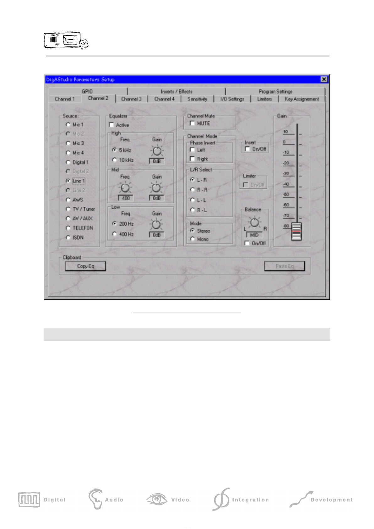
3Edit Controller
The Edit Controller functions are a subset of those of the D.A.V.I.D. Hardware Controller EdiDesk. For
the controlling of editing software a jog wheel and a number of different function keys are provided.
By default the buttons are assigned the most import Edigas or Multitrack Editor functions:
•Jog wheel mode: SCRUB / SKIP
•Edit functions: SET MARKER, MARK IN, MARK OUT, CUT INSIDE,
CUT OUTSIDE, UNDO, REDO
•Transport functions: PLAY / STOP, RECORD, FF, FREV, JUMP TO PREV
MARK, JUMP TO NEXT MARK, PLAY CLIP
•Trim functions: LOOP FROM, LOOP TO
•General functions: COPY, PASTE, UP, DOWN
Jog wheel with edit function keys
1With external synchronization only digital output 1 is available.

DigaStudio: Functional Specification Page 11 of 14
Special function: TIME STAMP (¿) - allows the storing of the current time in the interface unit for later
processing by the PC software. The time stamps can be printed out or converted to markers for the
editing software (e.g. to find specific passages in a recording which was run in the background).
4PC control
By connecting a PC to the interface / signal processing unit, any function can be controlled remotely by
the PC software. Mainly, this is used for configuration purposes and for execution of more complex
functions not available through the control pad (i.e. filters, insert/effect settings etc.). Also, user profiles
can be saved and restored this way, as well as updates of operating or DSP software.
Some examples of functions available through the PC interface:
•Input sensitivity for each source
•Filter: on/off, filter parameter, graphical frequency display
•Limiter: limiter parameters
•Control of inserts/effects
•selection of L+R, L or R
•phase inversion for a channel
•Saving and loading of user-profiles by means of the PC
•Configuration of GPIOs
•Configuration of key assignments
•Download and storing of the operating system software (non-volatile)
The connection to the PC is performed by means of a special protocol, based on the RS-422 interface.
By using the supplied communication driver any applications (i.e. other manufacturer´s editing
software) can communicate with the DigaStudio.
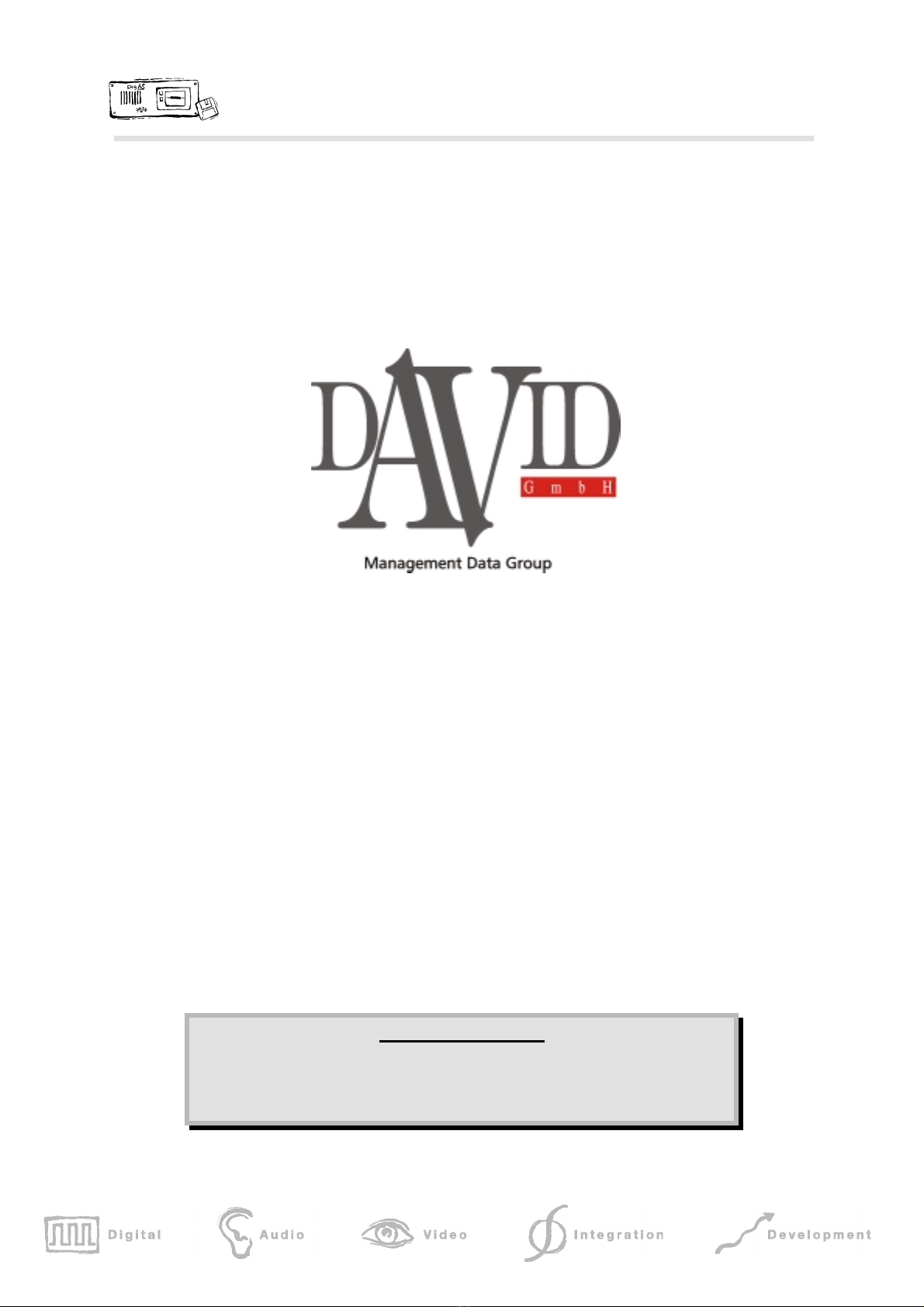
DigaStudio: Functional Specification Page 12 of 14
Screen shot of PC software (channel 2 selected)
5Accessories
Standard accessories are:
•Power cable
•Connecting cable interface unit control pad
•RS-422 cable incl. RS-232/422 adapter to be inserted into the PC
•Communication driver for the PC
•PC software for the configuration and control of various functions
Optional extras:
•Button labels (input selection, preview matrix, function buttons)
•Audio cable for direct connection DigaStudio PCX card
•Gooseneck microphone (e.g. AKG C 580-1)

DigaStudio: Functional Specification Page 13 of 14
•Software for central configuration of any DigaStudio connected to a network
6Technical Data
Power supply 110 ∼220V / 50 Hz
Power consumption app. 30 W
Dimensions
Control pad (w x d x h): 330 x 260 x 8 - 60 mm
Interface unit 19“, 2 HE x 365 mm
DigaStudio: Functional Specification Page 14 of 14
Landsberger Strasse 87
80339 Munich
Munich
Tel: +49 89 540 139 - 0
Fax: +49 89 540 139 - 50
Document information
Author: Andreas Hildebrand Revision date: 17.03.03
File:
\\pluto\daten\david\produkt\digastudio\applnote\appnotedigastudio_e97.doc
This manual suits for next models
1
Table of contents
Popular Music Mixer manuals by other brands

BOSSCO
BOSSCO Gigcaster 5 Reference manual

Tripp Lite
Tripp Lite B021-000-19-HD2 owner's manual

Body Craft
Body Craft T1000AC owner's manual

IMG STAGE LINE
IMG STAGE LINE PMX-800DSP instruction manual

Wyrestorm
Wyrestorm Express EXP-CON-4K-DD quick start guide

Sound Sation
Sound Sation YOUMIX Series user manual


