Davies Pump Hydropak-Xtra HP150 User manual

1
Year
Warranty
The Hydropak is covered by the Argon 3Year Warranty for
your piece of mind. Register online for extended warranty.
argondistributors.co.nz/warranty-registration
For correct operation & installation, it is essential to observe these instructions
OWNERS MANUAL

2 3
Proven solutions through experience
Ever Since the irst satisied customer in 1931, Davies Pumps have
become a trusted leader in the pump manufacturing industry.
From making deep-well pump cylinders in a North Shore
Basement to the wide range available today, Davies Pumps
focuses on providing the right solution for you and your family.
Contents
Contents
Argon Customer Service........................................................................................................4
Warranty Registration for Extension ......................................................................................5
Overview. .............................................................................................................................. 6
Scope of Delivery .................................................................................................................. 8
Choose Your Location .......................................................................................................... 9
Power Surge Protection ........................................................................................................ 9
Installation Requirements. ...................................................................................................10
Initial Installation ...................................................................................................................11
Ultraviolet lnstallation........................................................................................................... 12
Initial Setup .......................................................................................................................... 14
Final System Operation....................................................................................................... 15
Replacement Parts Guide .................................................................................................... 16
Cartridge Replacement........................................................................................................ 17
UV Lamp Replacement ........................................................................................................ 18
UV Sleeve Maintenance ...................................................................................................... 20
Pump Maintenance...............................................................................................................22
Troubleshooting Guide ........................................................................................................22
Pump Instructions ................................................................................................................26
HydroGenie 3.1 Controller................................................................................................... 30
HydroGenie 8 Controller..................................................................................................... 34
Warranty Policy.................................................................................................................... 45

4 5
Warranty Registration
The Argon 3 Year Warranty covers the Hydropak®-Xtra for your peace of
mind
ARGON PLUS+ Warranty Extension
Register your Hydropak®-Xtra online for an additional
1- Year Warranty free of charge
https://argondistributors.co.nz/warranty-registration/
Argon Customer Service
Congratulations on your purchase of a Davies Pump Hydropak®-Xtra, the all-in-one Pump, Multistage
Filtration & UV Sterilisation Water Supply System. You are about to enjoy the experience of
pressurised and healthy water throughout your entire home.
Like all Davies Pumps products, quality and reliability are irst and foremost for this proven brand
name, chosen to deliver years of service.
Please check your Hydropak®-Xtra(HPX) for any physical damage during transit and advise your
supplier if there are any issues.
Please check the nameplate to make sure the correct model has been supplied.
Please carefully read the following instruction and installation guide to ensure this is set up correctly
to give a long and trouble-free service life.
Product Information
Dealer
Installer
Installer phone
Date Installed
Serial Number
Year
Warranty
Warranty Registration & ExtensionArgon Customer Service

6 7
Overview
The HPX system combines a high-quality self-priming pump, advanced pump control with dual-stage
sediment iltration and ultraviolet water treatment to provide clean, safe pressurised water for your
home. The housing is designed and manufactured in NZ to meet our harshest conditions yet blend
into the landscape and protect your equipment.
Cartridge pre-iltration removes sediment that could reduce ultraviolet (UV) eectiveness and water
clarity.
The incorporated Greenway® UV Advance Series™ ultraviolet technology system is a natural
puriication process that’s completely eco-friendly, chemical-free and kills 99.9% of bacteria,
including E. Coli, Giardia, and Cryptosporidium. This process is critical for untreated water supplies
such as rain tanks, bores or other back up water supplies.
Note: water quality will adversely aect the performance of your UV disinfection system, and the
following levels should be utilised as a guideline for pre-treatment requirements of the inluent water
supply before UV treatment:
• Iron Total iron count must be less than 0.3 ppm (0.3 mg/L)
• Turbidity Count must be less than 1 NTU
• Tannins Count must be less than 0.1 ppm (0.1 mg/L)
• Manganese Count must be less than 0.05 ppm (0.05mg/L)
• Hardness Count must be less than 120 ppm (7 grains per gallon)
• %UVT (transmittance) Must be greater than 75%
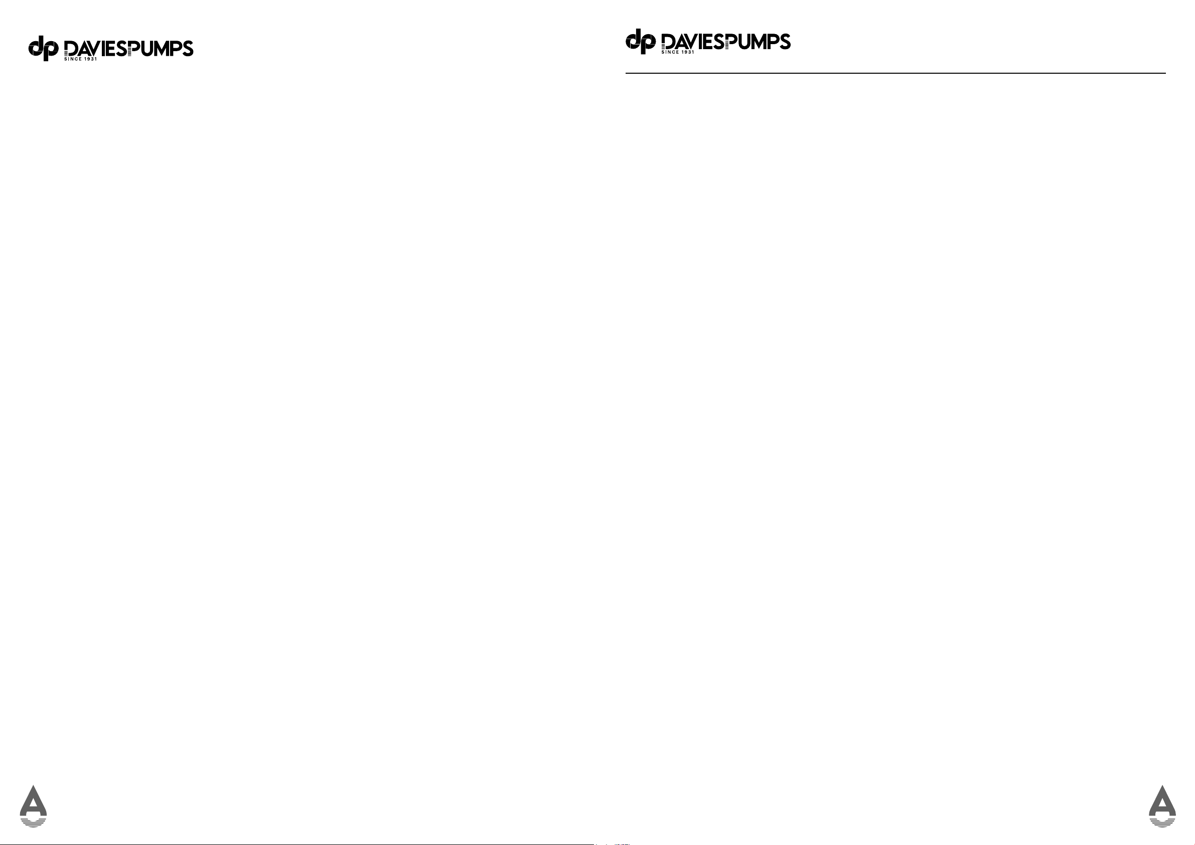
The HPX system cartridges and lamp need regularly replacing to maintain optimum performance.
This is a simple procedure when following instructions. For replacements, contact your nearest
Davies Pumps Filtration stockist.
Your new HPX system incorporates a failure warning feature that warns you of a lamp failure by a LED
warning light and an audible alarm. The alarm sounds when the lamp is due to be changed to ensure
eective treatment is maintained. A green LED indicates that the system is operating correctly.
Your HPX will arrive thoroughly tested from the factory and require minimal
installation to save you time and money.
MODEL NUMBER HP150 HP160 HP165 HP166
Pump Model: DJS 100M MPRS 0310M MPRS 0515M MPRS 0515T
Pump Type Self Priming pump Self Priming Multi-Stage
Pump Sound Medium Quiet
Rated Power: 1Hp 1Hp 1.5Hp
Maximum Current Consumption 4.5A 4.4A 6.5A
Pump Flow Rate 30 LPM @ 30M 60 LPM @ 30M 105 LPM @ 30M
Pressure Controller: HG 3.1 HG 8 VFD
Power Supply: 230V 1 Ph
Energy Saving Tank NA YES
Water Temperature Range 0600C (Protect from freezing)
Connection 1” BSP (25mm)
Warranty 3 Years (extension via registration)
First Line Defense
Dual cartridge ilters for maximum
life and iltration 10” and 20” options
available.
Optimum Control
Pressure gauge on ilter outlet and pump controller
to show if the ilters are blocked and allow for timely
replacement.
Durability
Weatherproof housing made of powder-coated
galvanised steel is designed to survive the harshest
New Zealand conditions. Choice of powder coat colors
available.
Stainless Steel options available.
Dimensions: 1000mm x 1000mm x400mm
Silent Night
Optional sound deadening panels for silent operation.
Plumb & Run
Simple plumbing connection with 25mm inlet/
outlet ports on either left or right.
*Option to have uniltered water take o for
irrigation. **Option for 32mm ports
Heat Control
Ventilation on both sides and around the roof to keep ambient
temperatures cool even in the toughest conditions.
Pump Control
HydroGenie HG3.1 or HG8 VFD pump control options for system
protection and provide optimum user experience.
*HG8 only on large model.
Second Line Defense
High volume 10S UV treatment and quality
ballast with 365-day timer and audible alarm
Functionality
Storage for replacement ilter
cartridges and ilter spanner..
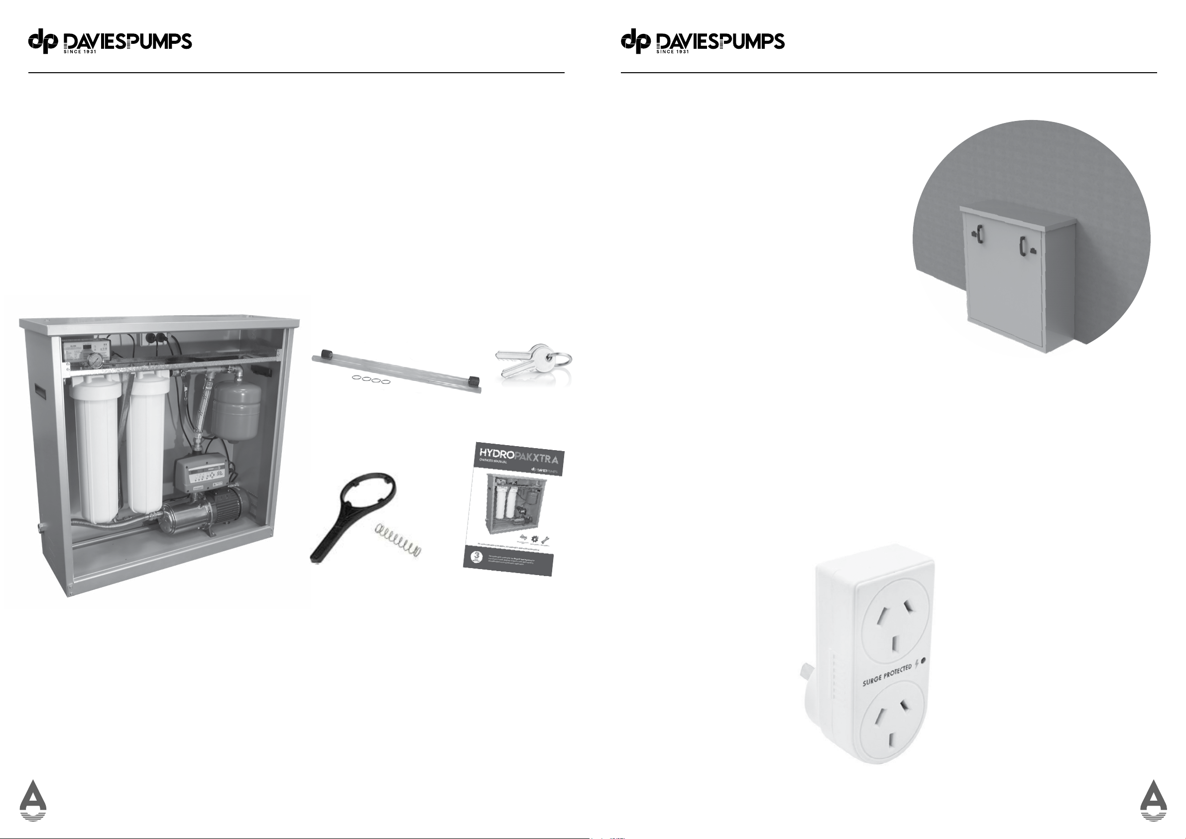
Power Supply
230V 10A single Ph power supply required.
Increased Eiciency
Using a Flexpansion pressure tank increases
eiciency and pump life by reducing cycle time and
also prevent shocks on system from water hammer or
thermal expansion.
Easy As
Convenient lifting handles to make delivery and installation
easy. Removable door and lid for easy servicing of ilters,
UV and pump.
Tamper Proof
Lockable door to prevent theft or tampering
but allowing easy access for maintenance
High Flow
High quality self-priming multistage MPRS pump
models to meet any conditions.
Options:
DJS100M with 30LPM @ 3.0bar duty
MPRS0310 with 60LPM @ 3.0bar duty
MPRS0515 with 105LPM @ 3.0bar duty
*Filter condition will aect performance.
OverviewOverview

8 9
Scope of Delivery
The HPX system is designed for many years of use but does require correct installation and periodic
maintenance.
Please read all instructions carefully as failures caused by incorrect installation or operation will not
be covered by warranty.
The HPX system is supplied as a complete unit. The UV lamp, sleeve, o-ring & spring are provided
separately in cardboard packaging and must be itted before use. There is also a bag with the owners
manual, keys & ilter spanner.
Hydropak®-Xtra
UV Lamp
Spanner
Keys
Owners Manual
Choose Your Location
The HPX must be installed on a level, frost-free
pad with adequate ventilation.
Ensure your location has suicient drainage in
case of spillage when servicing.
There must be suicient free space above the
unit to allow for servicing of the UV
lamp and sleeve.
Installation Clearances
• Width: 1200mm total
• Front: 1000mm
• Height: 1800mm (700mm required
above the unit for UV ilter replacement)
700mm required above the
unit for UV ilter replacement
Surge Protection
The UV ballast is supplied with a single-use surge protector to prevent damage from electrical
spikes (not lightning). It is the responsibility of the user/owner to check and replace the protector if
it has activated.
Spring
Scope of DeliveryScope of Delivery

10 11
Installation Requirements
• Water supply: Coldwater line only 0 - 52 °C (protect from freezing)
• Supply pressure: Maximum of 5bar static pressure (install pressure limiting valve if
pressure exceeds maximum pressure of 10bar.)
• The water supply must be no more than six meters lower than the HPX, and the suction
line must be no less than 25mm diameter (recommend 32mm for more than 10m
lengths)
• Foot valve installation recommended if the water source is lower than the HPX.
• Power supply: 10A 230V 50Hz RCD protected power supply for the three-pin AS/NZ
plug. The power supply must be suicient to operate the pump and UV system and be
protected from the weather or a suitable outdoor-rated socket (end-user to supply).
• Standard ports are 25mm BSP. A qualiied person must connect the ports to ensure
there are no leaks. HPX units are supplied with the suction port on the left and the
discharge port on the right. This coniguration can be changed if required. Please
contact your supplier.
• Use suicient thread seal tape to ensure an watertight seal and do not overtighten.
Note: Only use thread seal tape. Do not use liquid sealant.
• Use unions at pipe connections to enable easy removal and servicing.
• Always support heavy inlet and outlet pipes to prevent strain on the unit.
Installation Procedure
• Position the HPX unit on chosen location using a hand cart or a second person.
• Note: Do not attempt to lift single-handed.
• Open the main door by unlocking and releasing the two catches. Raise the door till the
bottom is clear of the base, tilt and lower the door to remove—the reverse procedure to
install.
• Remove the lid by undoing the two wing nuts under the top and lift o.
• Fix the HPX unit by bolting down to the pad with suitable concrete ixings. Remove the ilter
housings to allow more room and drill through the main base to provide ixing locations.
Initial InstallationInstallation Requirements

12 13
Speciications Standard Output
GAUV105
Flow Rate GPM US (LPM) (1)
16 mJ/cm (2) 29.5 (111)
30 mJ/cm (2) 15.5 (58)
40 mJ/cm (2) 11.5 (43)
Dimensions
Ballast 8” x 3” x 2”
Chamber Diameter 3.5”
Chamber Length 27.88”
I / 0 Port Size 3/4” FNTP - 1.0” MNPT
System Maximum Operating Pressure 125psi
Pressure Drop at 30 mJ/cm Rated Flow (psi) 0.5
Electrical
Voltage 100 - 240, 50/60 Hz
Power Consumption (W) 35
Lamp Watts (W) 30
Chamber Material 304SS
Always use soft gloves or a clean cloth when handling the UV lamps and quartz sleeves to prevent oil
deposits on the surface. Oil deposits from your hands can create hot spots on the surface, leading to
premature bulb failure.
Fit the UV sleeve
• Unscrew the VuCap.
• Remove the UV chamber retaining nut.
• Remove UV sleeve from packaging using a lint-free cloth, slip the O-ring approximately 10mm down
over the open end. Ensuring the sleeve is centrally located, carefully insert the closed end into the
chamber and slide into the central locator at the far end.
• Insert the spring into the sleeve.
• Fit the lower half of the VuCap to the chamber
• Reit and tighten the retainer nut, ensuring the O-ring and sleeve are irmly in place for a
complete seal.
Ultraviolet Sleeve & Lamp Installation
Fit the UV Lamp
• Remove the UV lamp from the packaging with a lint-free cloth.
• Connect the UV lamp plug to the bulb.
• Insert the UV lamp into the sleeve until it rests on the spring.
• Connect the top part of the VuCap over the lamp lead and connect to the lower VuCap part
on the chamber.
• For systems that have not had any prior treatment, lushing the pipework with a suitable
sanitiser is recommended. The sanitiser can be added to the water source or the ilter
housings and allowed to sit overnight before thorough lushing of pipework.
Ultraviolet Sleeve & Lamp Installation
Outlet Port
Inlet Port
Power cord Lamp connector
Ballast
UV Chamber
Quartz Sleeve
Spring inside
quartz sleeve
VuCap
ORing
UV Lamp
Retaining Nut
1 2 3 4
Ultraviolet InstallationUltraviolet Installation

14 15
Initial Setup
• Now all plumbing connections are complete, check the ilter housings are tight, the UV
lamp is itted, and the taps are open.
• Prime the pump through the iller port in the pump casing until full.
• Switch the power on at the supply and switch on the pump socket. The pump will run
and leave the discharge open until all the air has purged out and the system is primed.
• Switch on the UV and wait 23 minutes to allow the bulb to heat up.
• Close the discharge valve, and the pressure gauges will rise, and the pump will turn o.
• The system is now ready for normal operation. Open the discharge valve and check the
taps in the house are all working.
Final System Operation
• The recommendation is to leave the UV on at all times to ensure all water is being treated.
Leaving the UV unit on can mean the water in the chamber will heat up when not in use,
and condensation may appear on the UV chamber; this is normal.
• The HPX system is supplied with either the HG3.1 auto controller or the HG8 variable
speed/constant pressure controller. For speciic instructions on adjusting the controllers,
please see pages 30 or 34
• The controller has a digital pressure gauge. There is a second gauge after the iltration
units – this is to show the pressure dierential over the ilters and indicate if they are
blocked (the more signiicant the dierential, the more blocked they are).
• If the system is not going to be used for some time, we recommend switching the power
and taps o to prevent property damage in case of a component failure.
• If there are freezing conditions, the pump, ilters, and UV chamber must be drained of
water to prevent damage.
Final System OperationInitial Setup
Second Gauge
Controller Pressure Gauge

16 17
Replacement Parts Guide
• Regularly changing the ilter cartridges will maintain a high quality of puriied water.
• Replace them every 36 months or when there is a noticeable pressure drop.
(dependent on water quality and usage)
• You can order replacement cartridges via the Argon Distributors website
(www.argondistributors.co.nz) as ‘Click’n’Collect’ from your local Davies Pumps dealer.
Replace cartridges every 36 months. UV Lamps must be replaced annually to ensure optimum
water quality.
Replacement Parts Stage 1 Filtration Stage 2 Filtration UV Lamp UV Quartz Sleeve
Suits All Models BB20L20 BB20PS01 BBUVLAMP10S BBUVSLEEVE10S
Shut O Valve
Pressure relief buttons
Cartridge Replacement Procedure
The HPX is itted with a dual 20” cartridge ilter system. The irst ilter (right side) is a
20-micron polyspun cartridge and the second (left side) is a 5-micron polyspun cartridge.
The irst cartridge is to remove large particles, and the second cartridge is to remove smaller
particles which would reduce the UV eectiveness.
The ilter cartridges will require regular replacement to maintain optimum eectiveness.
Replace them 36 monthly or when there is a noticeable pressure drop. The cartridges may
also require lushing or replacement if the system has not been used for a long time.
Caution: Only use genuine replacement cartridges, or potential damage may not be covered
by warranty.
To change the ilter cartridges, please adhere to the following procedure:
• Turn the water supply o using the shut-o valve located inside the HPX unit.
Relieve the pressure by opening a downstream tap or pressing the red pressure-relief
button on the ilter housings.
• Unscrew the ilter bowls. Use the spanner to assist if they are tight. Remove the cartridges
and dispose of them according to local guidelines.
• Clean the bowls with warm water and soap. Check O-rings and replace if damaged. Lightly
lubricate with food-grade lubricant or similar.
• Remove all packaging from new cartridges and install them into the bowls, ensuring they
center on the base location.
• Hold bowls upright while screwing back into the housings. Ensure that the ixture in the
housing heads is located centrally to the cartridges to make a good seal. Tighten the bowls
until irm. HAND TIGHTEN ONLY. DO NOT OVERTIGHTEN.
• Open a downstream tap to allow air to be released and slowly open the water supply
allowing all air to be purged. Let the pump run for 23 minutes to purge air and lush the
system.
• Close the downstream tap and check for leaks.
• Reit the door
Cartridge ReplacementReplacement Parts Guide

18 19
UV Lamp Replacement Procedure
During normal operation of the system, the green power LED light will be illuminated, and the
display will indicate the number of days remaining until lamp replacement is required.
The following instructions for general maintenance of the system and UV lamp replacement/
quartz sleeve cleaning or replacement. An accredited service technician must complete all other
system repairs.
Caution: Only use genuine replacement lamps, or potential damage may not be covered by
warranty.
WARNING
• The lamp heats up after continuous use and can burn your skin if touched, allow the lamp to
cool for at least 5 minutes before removing.
• Do not operate the UV lamp outside of the reactor as it emits powerful ultraviolet light that
can cause permanent damage to the skin and eyes. Never look at the lamp when the unit is
turned on.
• Handle the UV lamp by the ends only, do not touch the bulb of the lamp with your ingers.
• If the lamp’s surface becomes dirty, use a clean lint-free cloth and isopropyl alcohol to
remove the dirt or oil. Dirt or oil deposits on the surface may lead to premature failure of
the bulb.
Your UV system includes a visible/audible lamp failure indicator. In the event of a failure of the
UV lamp, the red LED light will lash, and a loud beeping will be audible from the electronic
ballast of the unit. The lamp life countdown timer will stop counting.
Please note that if these conditions occur and you are on an untreated water source, you
should immediately stop using the water for potable applications until the lamp is replaced and
disinfection of the distribution lines is completed.
The ultraviolet lamp has an approximate life of one year (9000 Hours). The built-in 365-day
countdown timer displays the number of days remaining until lamp replacement is required.
When the countdown timer reaches 0-days, an intermittent audible alarm will be activated, and
the display will indicate alarm A3.
To allow time to obtain a replacement UV lamp, the audible alarm can be silenced for seven days
by pressing and holding the button on the ballast for 25 seconds. After seven days, the alarm
will sound again if the lamp has not been replaced. This can be done a maximum of four times
which allows a total of 28 days to obtain a replacement UV lamp. After four times, the alarm can
no longer be silenced until a replacement lamp is installed. Then the lamp life alarm is reset to
365 days by pressing and holding the button for 10 seconds.
UV Lamp Replacement Procedure
• Remove the door and lid from your HPX system.
• Turn the water supply o using the shut-o valve located inside the HPX unit.
Relieve the pressure by opening a downstream tap or pressing the red pressure-relief button
on the ilter housings.
• Unplug the ballast from the electrical outlet. Allow at least ive minutes for the UV lamp to
cool.
• Unwind the VuCap and release it from the chamber.
• Carefully lift the lamp out of the chamber quartz sleeve by gently rotating/lifting the
lamp free.
• Disconnect the plug from the lamp and discard the lamp in an approved manner.
• Remove the new lamp from the packaging using a lint-free cloth and reconnect the
plug. Lower the new lamp into the sleeve and reconnect the VuCap.
• Open a downstream tap to allow air to be released and slowly open the water supply
allowing all air to be purged. Let the pump run for 23 minutes to purge air and lush
the system.
• Close the downstream tap and check for leaks.
• Plug the ballast into the electrical outlet.
• Ensure that the UV lamp is operating by checking that the green power LED light is
illuminated. The red lamp failure LED light should be o, and no audible alarm should
be active.
• The ballast display will show the number of days until lamp replacement is required.
If a new lamp was installed, press and hold the button on the ballast for 10 seconds to
reset the countdown timer.
• Reit the lid and door.
1 2 3 4
UV Lamp ReplacementUV Lamp Replacement

20 21
UV Sleeve Maintenance/ Replacement Procedure
Mineral deposits and sediment build-up on the quartz sleeve will aect the system performance
by decreasing the UV light transmitted through the quartz sleeve into the water column.
The proper maintenance and replacement of the pre-iltration required for the UV system will
reduce the accumulation of mineral and sediment residue on the quartz sleeve.
The quartz sleeve can be cleaned with a commercially available, non-abrasive, scale remover
(acidic) and a lint-free cloth. Cleaning of the quartz sleeve should be done regularly to ensure
maximum system performance. The amount of cleaning required will vary depending upon local
water conditions.
All traces of the cleaning solution must be fully removed from the sleeve before it is reinstalled
in the system. Take care to prevent any cleaning luid from coming into contact with the inside
surface of the quartz sleeve.
Caution: Only use genuine replacement UV sleeves or potential damage may not be covered by
warranty.
• Remove the door and lid from your HPX system.
• Turn the water supply o using the shut-o valve located inside the HPX unit.
Relieve the pressure by opening a downstream tap or pressing the red pressure-relief button
on the ilter housings.
• Unplug the ballast from the electrical outlet. Allow at least ive minutes for the UV lamp to
cool.
• Unwind the VuCap and release it from the chamber.
UV Sleeve Maintenance/ Replacement Procedure
• Remove the sleeve retainer nut and the sealing o-ring.
• Using a lint-free cloth, carefully lift the sleeve out of the chamber.
• Remove the spring and put it in a safe place for reitting.
• Carefully clean the sleeve using an alcohol-based cleaner – see details above. (UV sleeves
should be replaced every three years to maintain optimum performance)
• Reit the sealing o-ring to the sleeve’s open end, insert it into the chamber, and secure it with
the retainer nut.
• Insert the lamp and it the VuCap.
• Open a downstream tap to allow air to be released and slowly open the water supply allowing
all air to be purged. Let the pump run for 23 minutes to purge air and lush the system.
• Close the downstream tap and check for leaks.
• Plug the ballast into the electrical outlet.
• Ensure that the UV lamp is operating by checking that the green power LED light is
illuminated. The red lamp failure LED light should be o, and no audible alarm should be
active.
• Reit the lid and door.
• Carefully lift the lamp out of the chamber quartz sleeve by gently rotating/lifting the
lamp free. Store it in a safe place for reitting.
1 2 3 4
UV Sleeve MaintenanceUV Sleeve Maintenance

22 23
Pump & Controller Maintenance
The pump and controller do not require any special maintenance and should operate for many
years before requiring service.
A periodic visual check is suicient to detect any problems before they cause failure. Look for
leaks or unusual noises as this may indicate seal or motor bearing failure.
It is recommended that any pump or controller servicing is done by a service agent.
Always ensure power and water is disconnected before doing any servicing.
See details on the pump setup and maintenance on page 26
See details on the controller setup and maintenance for HG3.1 on page 30
and the HG8 on page 34
Troubleshooting Guide
Symptoms Possible Cause Possible Solution
No power • Power cord has been disconnected.
• Ballast and/or RCD breaker tripped.
• Ballast damaged.
• Check power connections.
• Reset ballast and/or breaker.
• Replace ballast.
• Check switchboard
Ballast or breaker
repeatedly trips.
• Connection between lamp and
lamp plug is wet.
• Short-circuit in the electrical
assembly.
• Clean and dry lamp pins and lamp
plug, check unit for leaks or condensa
tion.
• Replace ballast.
Leak at inlet or
outlet.
• Threaded pipe ittings are leaking.
• Cracked heads.
• Clean threads, reseal with Telon tape
and retighten.
• Replace heads.
Leak detected
from area of UV
chamber.
• Condensation of moist air on cold
chamber (slow accumulation).
• O-ring damaged, deteriorated
or incorrectly installed.
• Lamp/sleeve assembly not properly
installed (too tight or not tight enough)
• Control humidity or relocate unit.
• Inspect and replace if deteriorated.
• Check O-rings are in place.
• Tighten assembly hand tight.
System is
operating but
water tests
reveal bacterial
contamination.
• Equipment downstream of UV system
is acting as a breeding ground for
pathogens.
• Pathogens are residing in the
distribution lines post-UV.
• Lamp reached the maximum
lamp life.
• Ensure UV is the last piece of treat-
ment equipment. Ensure all distribu-
tion lines have been disinfected - see
page 10.
• Remove any pipe deadends and lush
with chlorine.
• Replace lamp on or before lamp
counter reached 0.
Lamp timer does
not read anything.
• Unit is unplugged.
• No power at AC power outlet.
• Power cord is damaged.
• Power surge caused damage to
electrical assembly.
• Plug unit into AC power outlet.
• Replace fuse or reset breaker.
• Replace power cord.
• Replace ballast.
Troubleshooting GuidePump Maintenance
Troubleshooting Guide
Symptoms Possible Cause Possible Solution
Leak detected at
ilters
• O-ring damaged, deteriorated
or incorrectly installed.
• O-rings dry.
• Filter cartridge not centered.
• Remove the sump, wipe the O-ring and
threads clean. Ensure the O-ring is
itted properly, then reinstall.
• Lubricate O-rings with suitable sealant.
• Remove sump, check for cartridge
damage, reassemble ensuring car
tridge is centered.
Red lamp blinks and buzzer sounds. • Lamp has reached or nearing the maxi
mum lamp life.
• Lamp is disconnected or faulty.
• Replace lamp on or before lamp
counter reached 0.
• Check lamp connection, replace if
needed.
Display lashing. • Power interruption. • Reset ballast.
No water. • Water is not reaching the pump.
• Water source low, pump run dry
failure.
• Check source and prime pump system.
• Siphon the water line ahead of the
pump.
Low pressure • Filters blocked • Replace ilters
Pump continuously running • Leak in plumbing system. • Close discharge valve - if pump stops
then leak may be in house plumbing.

24 25
Pump User Instructions
Surface Pump installation and Operating Instructions
Installation
Your Davies pump should be mounted on a irm level foundation in an area that is not susceptible
to looding or is exposed to the weather or wet areas.
Make sure your pump is situated in an area that is well ventilated; the maximum ambient
temperature must not exceed 40oc. (FIG C)
Connections
Piping
The piping must be ixed or anchored so as not to transmit any thrust, tension or vibration to the
pump.
The inlet pipe must be as short as possible, not smaller than the inlet of your pump and must be
correctly sized for the distance covered. All connections on the suction side must be perfectly
sealed and be able to withstand the suction created by the pump. Ensure that it does not rise
higher than the pump to prevent air locks.
If your pump is sucking from below itself a foot valve or check valve must be installed. If the pump
is being used with a pressure tank, a check valve must also be installed. Other applications may
also require a check valve. (FIG D)
A gate valve and pressure gauge should be itted to the discharge of the pump to maintain
optimum operating pressure.
The pressure in the pump must not fall below the minimum rated head of the pump during normal
operation.
Electrical
Before connecting your pump to the mains power supply, check that it is suicient to cope with
the motor consumption – see details on the pump. All single phase pumps under 10A are supplied
with cord and plug for New Zealand electrical outlets. Make sure the power supply is the same as
the details on the speciications label.
Single phase pumps have an internal overload but must also be installed with a Residual Current
Device (RCD).
Three phase pumps must be installed with overload protection supplied by the user and be set
around 510% higher than the full load amps shown on the speciication plate.
Electrical connections must be carried out by a qualiied electrician.
Starting
Before starting your pump, check the motor shaft turns freely, the electrical connections are tight
and secure, pipe connections are tight and thread seal tape or thread sealant has been applied.
Priming
Fill the pump body and the inlet pipe through the priming port with the liquid that is going to
be pumped (be sure the liquid is compatible with the pump, e.g. viscosity, suspended solids,
corrosive) (FIG A)
Put the priming plug back in and tighten.
Switch on the pump, if it is 3 phase observe the rotation -is it according to the rotation arrow
(FIG B), if not it will need to be changed. Now check the pressure gauge, if it reads zero after
1020 seconds the pump will need to be primed again.
Operation Instructions
Operation
Now that your pump has pressure, check that it is running within its operating parameters, if
the pressure is below the minimum head the gate valve on the discharge will need to be closed
slightly to allow the pump to run at a higher pressure. If the pressure is below the minimum
head stated on the name plate it will damage the pump.
Pressure systems
If the pump is being used as a pressure system (pressure switch and pressure tanks system)
the air pressure in the pressure tanks needs to be set correctly to allow the system to work
properly and protect your pump.
To set the air pressure in the tank, irst allow the pump to build up pressure to the turn o
point, with the pump now o open a tap to allow the pressure to drop slowly, observe the
pressure gauge on the system and note the pressure when the pump turns on. The air pressure
in the tank will need to be set at 25 psi below this point.
To check the air pressure in the pressure tank, switch o the pump, turn on the tap and allow
the pressure to drop to zero.
With a tyre air pressure gauge check the pressure in the tank and set it accordingly i.e. let
some air out of the tank or put some in with a tyre pump or air compressor to achieve the
desired pressure.
Check the pressure in the tank every 6 months.
If your pump is being used with an Auto controller there are no adjustments that need to
be carried out, the controller will automatically switch the pump on and o according to the
demand and protect the pump in the event of dry-run.
Maintenance
Surface pumps do not require any special maintenance apart from periodic visual checks for
any leaks or unusual noises.
Any leaking or unusual noises must be reported immediately as long term damage can occur.
If there is risk of freezing, the pump and pipe work must be completely emptied. (FIG E)
Always turn o the power to the pump before any maintenance or repair work is carried out.
Pump User Instructions

26 27
Before starting your pump check that the pump turns freely by inserting a screw driver into the
groove of the main shaft at the fan end of the motor.
Remove all tools and quickly turn power on and o, checking the cooling fan rotates the correct way.
Always make sure that your pump is well protected from the elements and suicient ventilation is
provided.
Hold pipe work in place securely so that there is no strain or misalignment which could cause
damage.
Correct and incorrect use.
Correct use
These pumps have been designed to pump clean water. Please make sure that the following
conditions are observed when using the pump.
• Max Water Temp
• Max Ambient Temp
• Max Operating Pressure
Incorrect use
These pumps should not be used for pumping dirty water or water with suspended solids, sea water,
sand, abrasive or corrosive substances.
• Pumping of explosive or lammable liquids.
• Pumping of water at a higher temp than the max stated in the speciication of the pump.
Warnings
The manufacturer and wholesaler decline all liability for accidents to persons, animals, damage to
property to the pump if the warnings are not complied with or if the pump has been tampered with.
The above will also render the guarantee invalid.
Preventative measures.
All electric pumps must be protected by the user from lighting strikes, looding or external water
damage , chemicals, dust, vermin, insects, overheating, dry running, dead head running, operating
below minimum operating pressure.
Never start your pump with wet hands, bare feet or your feet in the water.
Always disconnect the power supply before carrying out any operation on your pump.
All working / moving parts of the pump have protection covers. Do not remove any of these while
your pump is working.
If in doubt – ask
Happy Pumping
Pump User Instructions Pump User Instructions

28 29
Introduction
The HydroGenie 3.1 is an electronic pump controller with pressure and low sensors to manage a
single phase pump up to 2.2Kw (3.0Hp) and protect from run dry failure. The pump start pressure is
adjustable to provide accurate operation.
The LCD screen shows the pump operating pressure in either bar or PSI. The Alarm LED shows if pump
is in failure and low LED shows low switch is active.
The controller has ART (Auto Reset Test) function which will attempt to restore operation in case of a
run dry failure. This function can be turned o or adjusted to set the number and duration of attempts.
The screen can also be set to standby mode to save power.
Technical Features:
Rated motor power: 0.372.2Kw
Voltage: 1~ 110230V
Frequency: 5060Hz
Max. Current: 16A*
Cosi > 0.6
Protection: IP65
Max Water Temperature/Ambient: 50 ºC /60 ºC
Start pressure range: 0.54 Bar
Factory set start pressure: 1.5 Bar
Max Operating pressure: 8 Bar
Hydraulic Connection: 1” Male
New Weight: 1.3kg (without cables)
*Controller is supplied with leads and plugs rated up to 10A. Leads must be replaced and direct wired
to power supply by qualiied personal if motor current is more than 10A
.
Hydraulic Installation
The pump must be correctly primed before completing hydraulic installation.
The controller must be installed in a vertical position with the direction arrows upward and the inlet
opening connected to the pump pressure port and the outlet opening connected to the network.
It is recommended to install a union between the pump and controller and an isolating ball valve after
the controller.
Electrical Installation
The controller is supplied with leads and plugs to rated for 10A so it can be connected to power supply
and pump lead without special requirements. If the pump draws more than 10A, then leads must be
upgraded and connected directly to power supply as below.
Control Panel Status
The Hydrogenie HG3.1 uses an LCD screen, LED indicator lights and push buttons to display operation
and set up data.
Mode Screen Display
Operation Shows current operating pressure value.
Adjustment Shows set pump start pressure.
Alarm Shows alarm code. (see alarm menu)
Standby Shows 3 blinking dots.
Basic Coniguration Shows the sequence of basic coniguration values.
Advanced Coniguration Shows the sequence of advanced coniguration values.
• 0 - indicates lit LED
• (0) – indicates slow lashing
• ((0)) – indicates fast lashing
LED State Meaning
Bar
0 Indicates the current pressure reading is in Bar and pump not running.
(0) Indicates the current pressure reading is in Bar and that pump is operating.
PSI
0 Indicates the current pressure reading is in PSI and pump not running.
(0) Indicates the current pressure reading is in PSI and that pump is operating.
Start 0 Indicates the set start pressure.
(0) Screen shows pressure value when adjusting the start pressure.
Flow 0 Indicates positive low.
Ⓐ
Alarm
0 Dry run failure. (ART function o)
(0) Dry Run Failure and ART active to attempt restore.
WARNING: All connections must be done by qualiied personal in accordance with all National
electrical codes. Ensure all wiring is disconnected from mains supply before installation. Earth
connections must be done irst.
Verify the power supply is between 110 and 230V. Use cables with enough section to power
requirements.
Remove the main cover from controller.
Fit gland cap and seal to motor supply lead and feed lead through the cable gland and do
connections: Earth - U - V. Tighten the gland cap irmly to prevent water ingress.
Fit gland cap and seal to mains supply lead and feed lead through cable gland and do connections:
Earth – L1 – N. Tighten the gland cap irmly to prevent water ingress.
Reit the main cover and ensure screws are irmly tightened to maintain IP rating.
Warranty may be voided by damage caused by incorrect connections.
Hydrogenie 3.1Hydrogenie 3.1 instructions

30 31
BUTTON PUSH Meaning
Power Touch
When switch is on: Turns switch o.
When switch is o: Pump starts and runs until stop pressure is reached.
In coniguration menu: Sets value and moves to next setting.
Hold When switch is on: Turns switch o.
When switch is o: Pump starts and runs until button is released.
Up ▲
Touch Start pressure setting is displayed on screen for 3 seconds.
3s Hold Opens start pressure coniguration menu.
Touch In coniguration menu, increases set start pressure.
Down ▼Touch In coniguration menu, decreases set start pressure.
Start-up Conigurations
Before starting switch and pump system, ensure all hydraulic and electrical connections are done correctly
then follow steps for basic start up.
1. Connect to power supply and screen will show ‘OFF’.
2. Start the controller by pressing power button.
3. Press Up ▲and hold for 3s and start pressure value will lash on the screen and start LED will be
on.
4. Adjust required start pressure to between 0.5 and 4 Bar using the ▲or ▼buttons
5. Press power button to set value.
6. The controller is ready to operate.
7. For further settings see Basic and Advanced coniguration menus.
Basic Menu Conigurations
Basic menu conigurations can be set by simultaneously holding the ▲and ▼buttons for 5s, then using the
▲or ▼buttons to change each coniguration value and the power button to set and move to the next item.
Coniguration sequence is:
Item Value Action Factory
Setting
1 Bar PSI Select pressure display in Bar or PSI. Bar
Advanced Menu Conigurations
Advanced menu conigurations can be set by simultaneously holding the ▲+▼+buttons for 5s, then using
the ▲or ▼buttons to change each coniguration value and the power button to set and move to the next
item.
Item Value Action Factory Setting
1 Ar0 Ar1 Disables the ART system (Ar0) or activates (Ar1) Ar1
2 n0 n48 Sets the number of ART restore attempts between 1 and 48 48
3 T1 t40 Sets a time span for the restore attempt run time of 10 – 40 seconds 40
4 Sb0 Sb1 Standby disabled (Sb0) or enabled (Sb1) Sb0
5rs0 rs1 Restores factory settings (rs1) rs0
Warnings and Alarms
Warning Alarm Description Action
A01
0
Dry run
detection
When a dry run is detected, the pump will stop and can be restarted by
pressing the power button.
(0)
If the ART system is active it will attempt to restart the pump for the
set number of attempts and time span. The irst attempt is after 5 min
and then every 30min for up to 24H before inal failure. Pump can be
restarted at any point by checking water supply and pressing the power
button to restart.
A05 0
Damaged
Pressure
Transducer
Contact your supplier.
Pressure Sensor Calibration
If the pressure readings displayed on the screen are incorrect to actual operating pressure, the sensor
can be re calibrated by following the steps below. This step requires a manual gauge in the system.
Set zero pressure:
1. Open all taps so there is no pressure on the system.
2. Simultaneously press the +▲buttons until the display shows ‘0.0’ flashing.
3. Press power button to set.
Set maximum pressure:
1. Start the pump and run until the switch cuts out at stop pressure.
2. Simultaneously press the +▼buttons until the display shows a value and is flashing.
3. Adjust this value to what the pressure gauge is showing using the▲+▼buttons.
4. Press power button to set.
Note this should not be a regular occurrence, if it happens frequently please contact your supplier.
Hydrogenie 3.1Hydrogenie 3.1 instructions

32 33
Introduction
The HydroGenie 8 is an electronic pump controller with a variable frequency inverter, pressure transducer
and flow sensor to manage a single or three phase pump up to 10A 2.2Kw (3.0Hp) and maintain constant
pressure as well as protect from run dry failure and overload. The inverter also provides soft start/stop of
the motor to prevent water hammer and increase motor life and provides energy savings by operating the
pump only at the required speed necessary to maintain set pressure.
The HG8 can also be configured as a pair with master/slave operation to control two pumps with alternate
starting and operation. It can also be installed in a group of up to four units with communication via a central
communication device.
The HG8 has a simple and intuitive set up and operation menu which can be easily accessed via the control
panel with push buttons, LED indication lights and LCD screen.
The LCD screen shows the pump operating data including line pressure, set pressure, the instantaneous
current consumption and speed of the motor and flow activation. It also shows alarms when they occur.
The overload can be adjusted and set to protect the pump motor.
The controller has ART (Auto Reset Test) function which will automatically attempt to restore operation after
a run dry or over current failure. Parameters will remain set even if power supply is interrupted.
The AIS function will periodically start the pump if temperatures drop below 5 degrees to reduce pump
freezing. If temperatures drop below 0 degrees, then separate protection measures must be taken.
Alarm register records system failures, connection attempts and run hours, an optional volt free contact for
monitoring alarms can be fitted.
These is a separate contact for a low-level float switch cut out.
CLASSIFICATION AND TYPE
According to IEC 60730-1 and EN 60730-1 this unit is a control electronic device for pressure systems of
independent
assembly, action type 1Y (transistor output). Operating value: flow 2.5 l/min. Degree of contamination 2
(clean environment).
Impulse rating voltage: cat II / 2500V. Applied temperature for the ball pressure test: enclosure (75ºC) and
PCB (125ºC).
According to EN 61800-3 the unit is class C2
Technical Features:
Rated motor power: 0.37-2.2Kw
Supply Voltage: 1~ 230V
Output Voltage: 1~ 230V/3~ 230V
Frequency: 50-60Hz
Max. Current per Phase: 10 A (~3 230 V) / 9A (~1 230 V)
Max. Peak Current: 20% for 10s
Fuses: 20A for inverter and 10A for main supply.
Protection: IP55*
Max. Water Temp/Ambient: 40 ºC /50 ºC
Max. Set pressure: 12 Bar
Max. Operating pressure: 15 Bar
Max. Flow: 15,000 L/H
Hydraulic Connection: 1.25” Male Net Weight: 3.3kg
* Dependent on cable glands being installed correctly.
Hydraulic Installation
The pump must have a non-return valve on the suction port and be correctly primed before completing
hydraulic installation.
The internal flow sensor will protect pump from dry running but not loss of prime.It is recommended to
install the external level cut out switch to prevent loss of prime especially if the pump has a suction lift. -
see configeration menu.
The controller must be installed in a vertical position and the 1¼” inlet opening connected to the pump
pressure port and the 1¼” outlet opening connected to the hydraulic network.
It is recommended to install a union between the pump and controller and an isolating ball valve after the
controller to assist with future maintenance.
For pumps installed as a pair, the outlets must be manifolded together to ensure each unit is monitoring
the same line pressure.
1. Pump.
2. Check Valve
3. Ball Valve
4. Filter
5. Union
6. HG8 Controller
7. Pressure Tank
8. Ball valve
Hydrogenie 8Hydrogenie 8 instructions

34 35
Electrical Installation
WARNING: All connections must be done by qualified personal in accordance with all National electrical
codes. Ensure all wiring is disconnected from mains supply before installation. Earth connections must be
done first.
Please wait at least 2 minutes before doing any connections inside the controller to avoid electrical
discharges.
The controller is not supplied with cables or plugs. Use cables with enough section to power requirements.
Minimum of 3G1.5 for 230V mains supply and 3G1.0 for 230V motor supply (depending on cable length)
Ensure power is switched off and isolated before removing covers and doing any connections.
Ensure three phase motors are in low voltage connection (230V Delta).
Remove the main cover from controller and follow the indications on strip connectors.
Fit gland cap and seal to motor supply lead and feed lead through the upper cable gland and do
connections: Single phase – Earth, U, V / Three phase – Earth, U, V, W. Tighten the gland cap firmly to
prevent water ingress.
Fit gland cap and seal to mains supply lead and feed lead through lower cable gland and do connections:
Single phase – Earth, L1, L2. Tighten the gland cap firmly to prevent water ingress.
The HG8 has the option to add a volt free contact with 1A max current to transmit a signal to an alarm box
for audio or visual reference in case of a failure as detected by the controller. Please contact your supplier if
you require this.
It also has a low-level input for a float switch to switch the pump off when supply is low to prevent loss of
prime.
For master/slave connection, use the 4GX0.25 communication cable inserted through the lower gland.
Follow connection diagram including crossing over of (Tx/Rx) between units.
Refit the main cover, ensure the seal is fitted, cables are not pinched and screws are firmly tightened to
maintain IP rating. Warranty may be voided by damage caused by incorrect connections.
1. Pump Motor Supply
2. Minimum Level
3. Power Supply
4. Master/Slave Communication
Main Connection Diagram:
Motor Lead Connections:
Hydrogenie 8Hydrogenie 8 instructions

36 37
Note. Tx/Rx Connections must be swapped over between units.
Master/Slave Connection: Low Level cut out
Unit 1 Unit 2
1 – Blue (+15V) 1 – Blue (+15V)
2 – Brown (Tx) 2 – Grey (Tx)
3 – Grey (Rx) 3 – Brown (Rx)
4 – Black (Gnd) 4 – Black (Gnd)
1 LCD screen. Shows the pressure in working mode.
2MANUAL START-STOP push button.
3 Push button for ENTER or EXIT menu.
4 With these push buttons we can change programming values showed in the LCD screen (1).
5 ENTER for saving programmed values. Every press will go to the next field of the
CONFIGURATION MENU. Whenever we want to quit the configuration sequence press MENU (3).
6 • Led lights:
• LINE green: Electric supply. ON when it is connected.
• FAILURE red: Bright or intermittent depending on type of failure.
•PUMP yellow: When it is bright means pump working. It is lit with the pump stopped or when the
device is not connected.
• AUTOMATIC green: it is bright in AUTOMATIC mode . When it is intermittent in MASTER&SLAVE
mode it means that this device will be auxiliary in the following cycle .
7 ON/ OFF: It allows to change from AUTOMATIC to MANUAL mode or vice versa.
Control Panel Layout:
12 7
63 4 5
Hydrogenie 8Hydrogenie 8 instructions

38 39
No. Screen Description Push
0PLINE PON
03,0 bar 02,0
bar
Push MENU for 3 seconds to start coniguration sequence. 3s
1SET UP MENU This temporary message gives information about the software version. 3s
2LANGUAGE
ENGLISH
By mean of keys we can choose the languages: “LANGUAGE ENGLISH”, “LANGUE FRANÇAISE”,
“LINGUA ITALIANA” and “IDIOMA ESPAÑOL”
3INT. MAX. OFF
0.0
The rated current intensity of pump motor - from 0 to 10 A - is entered by means of the keys to
enable thermal protection of the motor. This value is given on the name plate of the motor. Press
ENTER to conirm.
4ROTATION SENSE
0 Hz
Using the START/STOP pushbutton verify the rotation sense of three-phase motor. By mean of keys
(0/1) we can change it. Press ENTER for validation.
START UP:
Connect the HG8 to the electric supply with the mains switch. Wait for 10 seconds while the HG8 is running
auto test.
The HG8 is supplied for connection to a three-phase motor as default. If it is running a single-phase motor,
please follow motor configuration menu:
1. Press and hold ‘Menu + Enter” buttons for 3s to open the expert menu. This menu allows the
integration/acceleration/deceleration and motor supply to be set. It is not recommended to change these
parameters.
2. Press ‘Enter’ three times to confirm initial values, then use the buttons to select ‘single-phase’
or ‘three-phase’ and push enter to confirm.
3. Disconnect from the power supply until the screen goes blank, re-connect to power supply.
• If the unit is started for the first time, it will directly open the configuration menu. The LCD screen will
display a message for language selection. Choose your language and start the configuration procedure
see CONFIGURATION.
• Once the unit is configured, switch to manual mode by pressing the AUTO On/Off push-button (green
LED off). Verify if the pump is correctly primed using the Start/Stop push-button.
• Press AUTO On/off. The unit is ready to operate.
• Set up and configuration is the same for master/slave operation – each unit must be set up
with identical parameters and the type of operation is selected during set up.
CONFIGURATION:
Press and hold the ‘Menu’ button to enter configuration menu and use buttons to change the values
and press ENTER for validation. After every ENTER, the next screen setting for the configuration sequence
appears. Whenever we want to quit the configuration sequence, press MENU.
INTEGRATION
20
ACCELERATION
10
DECCELERATION
10
MOTOR
THREE P: U V W
MOTOR
SINGLE P: V W
No. Screen Description Push
5MIN. SPEED
15 Hz
Using we can increase the lower limit of the speed of rotation of the pump´s motor.
6LEVEL PROBE NO If there is no external device for detecting the minimum water level, press ENTER to conirm.
Otherwise, change NO for YES using the keys
7PROGRAMMING Being inside coniguration menu we are having access to the main program section.
8SET POINT
2,0 bar
This will be the system operating pressure. Use keys to modify the initial value (2 bar).
WARNING ! The set pressure must be at least 1 bar lower than the maximum pressure of the pump.
NOTE: In case of group assembly, the system operates at the pressure set in the MASTER device so
that the coniguration of set pressure in the slave device is superluous.
9DIF. START
0,3 bar
The default value is 0,3 bar. This value of pressure is the one that the system will subtract from the set
pressure before the system starts when the hydraulic network has a demand. Using keys to modify
the initial value. It is recommended to maintain this value between 0,3 and 0,6 bar. Example:
- Input pressure: 2 bar.
- Dierential start: 0,3 bar.
- Final start pressure: 2 - 0,3 = 1,7 bar.
10 TIMER STOP
5
TIMER STOP default value is 5”. This will be the time the system will run for after the usage in the whole
installation has stopped. Using keys we can modify the initial value.
11 VIEW MODE
NORMAL
There are 2 view modes to choose:
- NORMAL: it is visualized “P LINE” (real pressure of the installation) and “INPUT P” (conigured
pressure).
- SERVICE: it is visualized “Hz” (working frequency of the inverter), “REF” (conigured pressure),
“PRESS” (real pressure of the installation) and “FL” (low sensor state).
12 SERIAL
CONTROL
SLAVE
The HG8 is conigured by default as “SLAVE”, with individual assembly just conirm “SLAVE” by
pushing ENTER.
In case of a pair with master/slave, change one unit to “MASTER” by pushing and leave the other as
‘slave’. It does not matter which unit is master.
In case of assembly of more than 2 devices, we will change all units from “SLAVE” to “SWITCHER” by
pushing twice - see instructions for communication centre.
13 DIRECTION
CH 1
It allows to set the communication channel for a group assembly. Push ENTER.
14 P LINE INPUT P
00,0 bar 00,0
After pressing ENTER pushbutton, the system is conigured showing the type of view chosen in the
previous section, Press AUTOMATIC in order to start automatic operation.
In case of group assembly press AUTOMATIC only in the device conigured as MASTER.
In case of group assembly, after pressing AUTOMATIC in the MASTER device, the AUTOMATIC LED
LIGHT of the SLAVE device will start to lash intermittently, indicating that communication between
both devices is ready. If this does not happen verify the connections are correct.
Hydrogenie 8Hydrogenie 8 instructions
This manual suits for next models
3
Table of contents
Other Davies Pump Water Pump manuals
Popular Water Pump manuals by other brands

Crane
Crane BARNES EP72X installation manual

Debem
Debem EQUAFLUX Series Instructions for use and maintenance

Graco
Graco Triton 308HP Instructions-parts list

Witt
Witt G01 instructions

TELLARINI POMPE
TELLARINI POMPE EEM Series User and maintenance manual

Pentair
Pentair Fairbanks Nijhuis 5900 Series Installation, operation and maintenance instructions