DAVIS Vantage Pro2 Updater User manual

Vantage Pro2
Console Manual
™
For Vantage Pro2 & Vantage Pro2 Plus Weather Stations
™™
Davis Instruments, 3465 Diablo Avenue, Hayward, CA 94545 • 510-732-9229 • www.davisnet.com

Vantage Pro 2 Console Manual
Document Part Number: 07395.234 Rev. H, May 2, 2008
For Vantage Pro2 Consoles # 6312 & 6312C
And Vantage Pro2 Weather Stations # 6152, 6152C, 6153, 6162, 6162C, 6163
Vantage Pro®and Vantage Pro2™are trademarks of Davis Instruments Corp., Hayward, CA.
© Davis Instruments Corp. 2006. All rights reserved.
Information in this document subject to change without notice.
FCC Part 15 Class B Registration Warning
This equipment has been tested and found to comply with the limits for a Class B digital device, pursuant to Part 15 of the FCC Rules.
These limits are designed to provide reasonable protection against harmful interference in a residential installation. This equipment
generates, uses, and can radiate radio frequency energy and, if not installed and used in accordance with the instructions, may cause
harmful interference to radio communications.
However, there is no guarantee that interference will not occur in a particular installation. If this equipment does cause harmful interfer-
ence to radio or television reception, which can be determined by turning the equipment on and off, the user is encouraged to try to cor-
rect the interference by one or more of the following measures:
• Reorient or relocate the receiving antenna.
• Increase the separation between the equipment and receiver.
• Connect the equipment into an outlet on a circuit different from that to which the receiver is connected.
• Consult the dealer or an experienced radio/TV technician for help.
Changes or modification not expressly approved in writing by Davis Instruments may void the warranty and void the user's authority to
operate this equipment.
FCC ID: IR2DWW6328
IC: 378810-6312
EC EMC Compliance
This product complies with the essential protection requirements of the EC EMC Directive 89/336/EC.
Vantage Pro2 Console Display Features
Display Features
1. Compass Rose
2. Graph & Hi/Low Mode Settings
3. Forecast Icons
4. Moon Phase Indicator
5. Time/Sunrise Time
6. Date/Sunset Date
7. 2ND Button Indicator
8. Barometric Trend Arrow
9. Graph Icon
10. Current Rain Icon
11. Station Number Indicator
12. Weather Ticker
13. Graph Field
14. Alarm Icon
N
S
WE
NE
SE
NW
SW
GRAPH 2nd
Vertical Scale: X10
WIND
RAIN RATE
in/hr
DAILY
in
STATION NO.1
pm
Last 24 hrs hr
Every 1
MPH
CHILL
TEMP OUT
HUM IN
HUM OUT
TEMP IN
hPa
BAROMETER
F
F
F
13
12 11 10
1
14 9
8
7
6
5
4
32

i
Table of Contents
Welcome to Vantage Pro2TM ............................................................................. 1
Console Features ..........................................................................................1
Vantage Pro2 Options ..................................................................................2
Installing the Console ........................................................................................ 4
Powering the Console ..................................................................................4
Installing the AC Power Adapter .................................................................4
Installing Batteries .......................................................................................5
Connecting Cabled Stations .........................................................................5
Console Location .........................................................................................6
Using Your Weather Station ............................................................................. 9
Setup Mode ..................................................................................................9
Current Weather Mode ..............................................................................18
Selecting Units of Measure ........................................................................19
Displaying the Forecast .............................................................................24
Displaying Time & Date or Sunrise & Sunset ...........................................24
Calibrating, Setting, and Clearing Variables .............................................25
Highs and Lows Mode ...............................................................................27
Alarm Mode ...............................................................................................29
Graph Mode ...............................................................................................31
Troubleshooting and Maintenance .................................................................. 34
Vantage Pro2 Troubleshooting Guide .......................................................34
Console Diagnostic Mode ..........................................................................36
Console Maintenance .................................................................................40
One Year Limited Warranty ......................................................................40
Appendix A Weather Data .............................................................................. 41
Appendix B Specifications .............................................................................. 47
Console Specifications ...............................................................................47
Wireless Communication Specifications ...................................................47
Console Data Display Specifications .........................................................48
Weather Data Specifications ......................................................................49
Appendix C ...................................................................................................... 51
Wireless Repeater Configuration .................................................................... 51
Vantage Pro2 Console Icons ......................................................................53

1
Chapter 1
Welcome to Vantage Pro2TM
Welcome to your Vantage Pro2 Weather Station console. The console displays
and records your station’s weather data, provides graph and alarm functions,
and interfaces to a computer using our optional WeatherLink®software.
Vantage Pro2 stations are available in two basic versions: cabled and wireless.
A cabled Vantage Pro2 station transmits outside sensor data from the Inte-
grated Sensor Suite (ISS) to the console using a straight-through four-conduc-
tor cable. A wireless Vantage Pro2 station transmits outside sensor data from
the ISS to the console via a low-power radio. Wireless stations can also collect
data from optional Vantage Pro2 sensors. See “Optional Sensors” on page 2.
The Vantage Pro2 Quick Reference Guide included with your station provides
an easy to use reference for most console functions.
Console Features
Keyboard & Display
The keyboard lets you view current and historical data, set and clear alarms,
change station models, enter calibration numbers, set up and view graphs,
select sensors, and read the forecast. The keyboard consists of 12 command
keys located next to the screen display and four navigation keys located below
the command keys.
A weather variable or console command is printed on each com-
mand key. Just press a key to select the variable or function printed
on that key.
Each command key also has a secondary function which is printed
above the key on the console case. To select the secondary func-
tion, press and release 2ND (on the front of the console, upper right
corner) and then immediately press the key for that function.
Note: After pressing 2ND, the 2ND icon displays above the barometer reading on the
screen for three seconds. All secondary key functions are enabled during this time.
Keys resume normal operation after the icon disappears.
The up arrow, down arrow, left arrow, and right arrow navigation
keys are used to select command options, adjust values, and to pro-
vide additional functions when used in combination with a com-
mand key.
WIND
CHILL
2
ND
+
-
<>

Vantage Pro2 Options
2
Console Modes
The console operates in five basic modes: Setup, Current Weather, Highs
and Lows, Alarm, and Graph. Each mode lets you access a different set of
console functions or display a different aspect of your weather data.
Vantage Pro2 Options
Optional Sensors
Vantage Pro2 stations are extremely flexible. Use the following optional
sensors and wireless stations to enhance the weather monitoring capabili-
ties of your Vantage Pro2. See our website for complete details:
www.davisnet.com.
Note: Optional wireless stations can only be used with Wireless Vantage Pro2 Stations.
Optional WeatherLink®Software
The WeatherLink software and data logger connect your Vantage Pro2
station directly to a computer, providing enhanced weather monitoring
capabilities, a continuous preserved data record, and powerful Internet
features. The WeatherLink data logger fits neatly on the console and stores
weather data even when the computer is turned off.
Optional Sensor and Stations Description
Wireless Weather Envoy (# 6316)
Cabled Weather Envoy (# 6316C)
Performs much of the same functions as a Vantage Pro2
console, but without a display. Use an Envoy to interface your
wireless station to a computer when you’d rather place the
console in another location for viewing weather conditions
Anemometer Transmitter Kit
(# 6332)
Provides more flexible anemometer placement for wireless
stations.
Wireless Leaf & Soil Moisture/
Temperature Station (# 6345)
Measures and transmits leaf wetness, soil moisture and
temperature data. Also for use with GLOBE.
Wireless Temperature Station
(# 6372) Measures and transmits temperature data.
Wireless Temperature/Humidity
Station (# 6382) Measures and transmits air temperature and humidity data.
Solar Radiation Sensor (# 6450)
Measures solar radiation. Required for calculating
evapotranspiration (ET). Available for cabled and wireless
stations. Requires Sensor Mounting Shelf (# 6673).
Ultraviolet (UV) Radiation Sensor
(# 6490)
Measures UV radiation. Required for calculating the UV dose.
Available for Cabled and Wireless stations. Requires Sensor
Mounting Shelf (# 6673).
WeatherLink Option Description
WeatherLink for Windows, USB
connection (# 6510USB)
Includes WeatherLink software and USB data logger. Allows you to
save and view your weather data on your PC.
WeatherLink for Windows, serial
connection (# 6510SER)
Includes WeatherLink software and serial data logger. Allows you to
save and view your weather data on your PC.

Vantage Pro2 Options
3
Optional Accessories
The following accessories are available from your dealer or may be ordered
directly from Davis Instruments.
Sensor Mounting Shelf (# 6673)
Required for mounting the optional Solar Radiation and/or UV sensors. The
mounting shelf attaches to the base of the rain collector on the ISS.
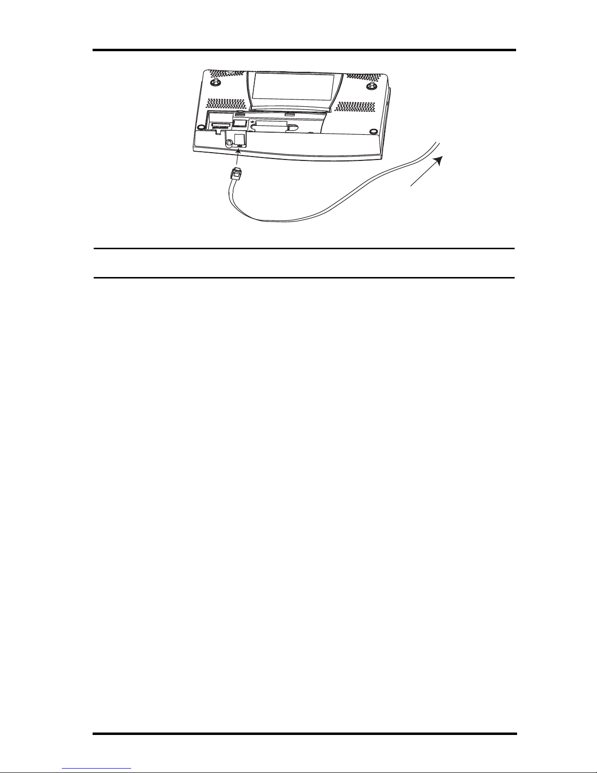
USB-to-Serial (DB-9) Cable (# 8434)
Allows the Serial version of WeatherLink (# 6510SER, 6540, 6550, 6560) to
connect to a USB port on your computer.
Telephone Modem Adapter (# 6533)
Creates a dialup connection between the station and the computer.
Extension Cables (# 7876)
Allows you to place the Cabled Vantage Pro2 ISS further away from the con-
sole using the extension cable provided by Davis Instruments. Maximum cable
length is 1000’ feet (300 m).
• # 7876-040 Cable, 40’ (12 m)
• # 7876-100 Cable, 100’ (30 m)
• # 7876-200 Cable, 200’ (61 m)
Davis Baseball Cap (# PR725)
100% cotton twill cap is two-toned with a washed khaki crown, dark blue
brim, and embroidered Davis logo. Self-fabric closure with brass buckle. One
size fits all.
WeatherLink for Macintosh OS X,
USB connection (# 6520)
Includes WeatherLink software and USB data logger. Allows you to
save and view your weather data on your Mac.
WeatherLink for APRS, Windows
version, with streaming data
logger, serial connection (# 6540)
Includes WeatherLink software and streaming serial data logger.
Allows real-time display of current weather conditions for use with
APRS (Automatic Position Reporting System), for HAM radio users.
WeatherLink for Alarm Output,
Windows version, with streaming
data logger, serial connection
(# 6544)
Includes WeatherLink software and streaming serial data logger.
Gives you the ability to control external devices based on various
combinations of weather trends and events.
WeatherLink IP for Windows 2000/
XP/Vista (#6555)
Requires a broadband router with available Ethernet port. Allows you
to post your weather data directly to the Internet without a PC.
Among other features, allows you to receive e-mail alerts of current
weather conditions or simple alarm conditions.
WeatherLink for Emergency
Response teams, Windows
version, with streaming data
logger, serial connection (# 6550)
Includes WeatherLink software and streaming serial data logger.
Allows real-time display of current weather conditions for use by
emergency response teams.
WeatherLink for Irrigation Control,
Windows version, with streaming
data logger, serial connection
(# 6560)
Includes WeatherLink software and streaming serial data logger.
Allows intelligent and efficient control of popular automated irrigation
systems using weather data.
WeatherLink Option Description

4
Chapter 2
Installing the Console
The Vantage Pro2 console is designed to give extremely accurate readings. As
with any precision instrument, use care in its assembly and handling.
Although installing the console is relatively simple, following the steps out-
lined in this chapter and assembling the Vantage Pro2 correctly from the start
will help ensure that you enjoy all of its features with a minimum of time and
effort.
Powering the Console
Cabled Vantage Pro2 Stations
Cabled Vantage Pro2 consoles supply power to the Integrated Sensor Suite
(ISS) through the console cable. Because of the added power consumption of
the ISS, the cabled console requires an AC power adapter used as the main
power supply. The console batteries provide backup power for up to four to
six weeks.
Wireless Vantage Pro2 Stations
Wireless Vantage Pro2 consoles do not require the use of an AC adapter. You
may use the included adapter if you wish, but the three C-cell batteries should
power a wireless console for up to nine months.
Note: When using an AC Power adapter, be sure to use the power adapter supplied with
your Vantage Pro2 Console. Your console may be damaged by connecting the
wrong power adapter. The console does not recharge the batteries. Because of this,
and because NiCad batteries do not power the console as long as alkaline batteries,
use alkaline batteries in the console.
Installing the AC Power Adapter
1. Remove the battery cover located on the back of the console by pressing
down on the two latches at the top of the cover.
2. Find the power jack located on the bottom of the console case.
Power Plug
Wrap Cord Around Pins

Installing Batteries
5
3. Insert the power adapter plug into the console power jack, then plug the
other end of the adapter into an appropriate power outlet.
4. Check to make sure the console runs through a brief self-test procedure suc-
cessfully. On power up, the console displays all the LCD segments and
beeps twice. A message displays in the ticker banner at the bottom of the
console, followed by the first screen that displays during Setup Mode. Press
and hold DONE to skip the message and enter into Setup Mode.
Setup Mode guides you through steps required to configure the station. See
“Setup Mode” on page 9 for more information.
Installing Batteries
1. Remove the battery cover located on the back of the console by pressing
down on the two latches at the top of the cover.
2. Insert three C batteries into the battery channel, negative (or flat) terminal
first.
3. Replace the battery cover.
Connecting Cabled Stations
Cabled Vantage Pro2 stations come with 100 feet (30m) of cable. This cable is
used for connecting the console to the ISS. Maximum cable length from ISS to
the console using Davis Instruments cables is 1000 feet. To connect the con-
sole to the ISS:
1. Firmly insert the console end of the straight-through four-conductor wire
into the console receptacle marked “ISS” until it clicks into place. Do not
force the connector into the receptacle.
Battery
Battery
Battery

Console Location
6
2. Ensure that the ISS cable is not twisted through the access port.
Note: The ISS must be assembled and connected to the console so that it is receiving
power before the console connection can be tested.
Once the console and ISS are both powered up, cable connection should be
tested and established.
Once the console is powered, it automatically enters Setup Mode. You can step
through the Setup Mode options, or exit the Setup Mode to test the connection
and sensor readings in Current Weather Mode. See “Setup Mode” on page 9
for Setup Mode options. See “Current Weather Mode” on page 18 for viewing
and verifying current weather data coming from the cabled console.
To verify that the console is receiving data from the ISS through the console
connection, see “Cabled ISS Assembly” in the Integrated Sensor Suite
Installation Manual.
Console Location
Place the console in a location where the keyboard is easily accessible and the
display is easy to read. For more accurate readings, follow these suggestions.
• Avoid placing the console in direct sunlight. This may cause erroneous
inside temperature and humidity readings and may damage the unit.
• Avoid placing the console near radiators or heating/air conditioning ducts.
• If you are mounting the console on a wall, choose an interior wall. Avoid
exterior walls that tend to heat up or cool down depending on the weather.
• If you have a wireless console, be aware of possible interference from
cordless phones or other devices. To prevent interference, maintain a dis-
tance of 10 feet between the Vantage Pro2 console and a cordless phone
(handset and base).
• Avoid positioning a wireless console near large metallic appliances such as
refrigerators, televisions, heaters, or air conditioners.
• The console antenna does not rotate in a complete circle. Avoid forcing the
console antenna when rotating it.
To ISS

Console Location
7
Table & Shelf Placement
The console kickstand can be set to three different angles allowing five differ-
ent display angles.
1. Install the two round rubber feet on the bottom of the console. The rubber
feet help prevent damage to furniture and surfaces.
2. Lean the kickstand out by pulling on its top
edge.
You’ll see the indentation for your finger at
the top edge of the console.
3. Slide the catch to rest the kickstand in the
appropriate angle.
Choose low angles for display on a coffee
table or other low area. Choose higher
angles for display on a desk or shelf.
4. Install the two rubber channel feet on the
kickstand.
If necessary, pull up on the stand to close it. It will be a little tight, so it’s okay
to push hard enough to get it to slide.

Console Location
8
Wall Mounting
The console mounts to the wall using two keyholes located on the back of the
case.
To mount the console on a wall:
1. Use a ruler to mark two mounting hole positions on the wall 8 inches (203
mm) apart.
This is a representation for the mounting hole positions. This template is not true to size.
If installing a cabled Vantage Pro2 console with sensor cable running inside
the wall, mount the console over an empty switch box.
2. Use a drill and a 3/32 or 7/64''(2.5 mm) drill bit to drill two pilot holes for
the screws.
3. Using a screwdriver, drive the two #6 x 1'' pan head self-threading screws
into the wall. Leave at least 1/8'' (3 mm) between the wall and the heads of
the screws.
4. If the kickstand has been pulled out from the case, push it back into its
upright and locked position.
5. Guide the two keyholes on the back of the console over the two screws.
Drill two 3/32" or 7/64" (2.4 to 2.8mm) holes
8" (203mm) apart for the #6 x 1" mounting screws.
8" (203mm)

9
Chapter 3
Using Your Weather Station
The console LCD screen and keyboard provide easy access to your weather
information. The large LCD display shows current and past environmental
conditions as well as a forecast of future conditions. The keyboard controls
console functions for viewing current and historical weather information, set-
ting and clearing alarms, changing stations types, viewing and/or changing
station settings, setting up and viewing graphs, selecting sensors, getting the
forecast, and so on.
Console Modes
The Vantage Pro2 console operates in five different modes:
Setup Mode
Setup Mode provides access to the station configuration settings that control
how the station operates. Setup Mode consists of a series of screens for
selecting console and weather station options. The screens that display in
Setup Mode vary depending on the weather station type (cabled or wireless),
or if the console has a WeatherLink connection already established. (See the
WeatherLink Getting Started Guide for more information on connecting your
console to your computer.)
Setup Mode Commands
Setup Mode displays when the console is first powered. This mode can be dis-
played at any time to change any of the console/weather station options. Use
the following commands to enter, exit and navigate Setup Mode:
• Enter Setup Mode by pressing DONE and the down arrow (-) at the same
time.
Note: The console automatically enters Setup Mode when first powered.
• Press DONE to move to the next screen in the Setup Mode.
• Press BAR to display the previous screen in the Setup Mode.
• Exit Setup Mode by pressing and holding DONE until the Current Weather
screen displays.
Mode Description
Setup Use Setup Mode to enter the time, date, and other information required to
calculate and display weather data.
Current Weather Use Current Weather Mode to read the current weather information, change
measurement units, and to set, clear or calibrate weather readings.
High/Low High/Low Mode displays the daily, monthly or yearly high and low readings.
Alarm Alarm Mode allows you to set, clear, and review alarm settings.
Graph Graph Mode displays your weather data using over 100 different graphs.

Setup Mode
10
Screen 1: Active Transmitters
Screen 1 displays the message “Receiving from...” and shows the transmitters
being received by the console. In addition, an “X” blinks in the lower right-
hand corner of the screen every time the console receives a data packet from a
station. The rest of the LCD screen is blank.
If you have a cabled station, or if your wireless ISS uses the factory settings
and you are receiving the signal, the screen displays “Receiving from station
No. 1.” Any optional stations that have been installed should also display.
Screen 1: Active Transmitters
Note: An ISS or optional station must be powered for the console to recognize it. Refer to the Integrated
Sensor Suite Installation Manual or optional station installation instructions for more information.
It make take several minutes for the console to acquire and display a Transmitter ID.
1. Make a note of the station number(s) listed on the screen.
2. Press DONE to move to the next screen.
The console can receive signals from up to eight transmitters total, but there is
a limit on the number of certain types of transmitters. The table below lists the
maximum number of stations allowable for a receiver:
Maximum Number of Transmitters in a Network with One Receiver
*Replaces the ISS anemometer.
**Two are allowable only if both stations are only partially populated. For example, A network can either have
both a Leaf Wetness/Temperature station and a Soil Moisture/Temperature station, or it can have one com-
bined Leaf Wetness and Soil Moisture/Temperature station.
Note: Listening to more than one transmitter may reduce battery life significantly.
Screen 2: Configuring Transmitter IDs — Wireless Only
(If you have a cabled station, press DONE and continue on to “Screen 4: Time
& Date” on page 12.)
Setup screen 2 allows you to change the ISS transmitter ID and to add or
remove optional transmitter stations. The default transmitter ID setting is “1”
(ISS), which works fine for most installations.
ST
A
TIO
N
N
O.
1
4
Station Type Maximum Number
Integrated Sensor Suite (ISS) 1
Anemometer Transmitter Kit*1
Leaf & Soil Moisture/Temperature Station 2**
Temperature Station 8
Temperature/Humidity Station 8

Setup Mode
11
Screen 2: Transmitter ID configuration
If you have a cabled station, or if you have a wireless station and are using
the default transmitter ID setting, press DONE to move to the next screen.
Note: Typically, you can use the default transmitter ID setting of 1 unless you are installing one of the
optional transmitter stations or a nearby neighbor has a Vantage Pro2 station that uses transmit-
ter ID 1 for the ISS.
3. Press the right and left arrows to select the transmitter ID.
When you select a transmitter ID, the ID number is displayed on the screen
as well as the current configuration.
4. Press the up or down arrows to toggle console reception of signals from
transmitters using that ID on and off.
5. Press GRAPH to change the type of station assigned to each transmitter
number. Scroll through the station types - ISS, TEMP, HUM, TEMP HUM,
WIND, RAIN, LEAF, SOIL, and LEAF/SOIL - until the correct type
appears.
6. Press DONE to move to the next screen.
Note: This screen contains functionality for enabling repeaters. If the word “Repeater” displays in the
right corner of the screen and you are not using repeaters as part of your network, see “Clearing
Repeater ID” on page 52. If you are using repeaters as part of your network see “Wireless
Repeater Configuration” (Appendix C) on page 51 for configuring repeaters on the console.
Screen 3: Retransmit — Wireless Only
Press DONE and go to “Screen 4: Time & Date” on page 12 if you have a
cabled station.
The console can take data it receives from the ISS and transmit it to other Van-
tage Pro2 consoles using the retransmit feature. By toggling the feature on, the
console becomes another transmitter that requires its own unique ID to trans-
mit the data received from the ISS.
Screen 3: Retransmit
1. Press the up or down arrow to turn the retransmit function on and off. The
first available transmitter ID not used by the ISS or any optional sensor is
automatically assigned. Data from the ISS is the only data that can be
retransmitted by the console.
When retransmit has already been enabled, pressing the right or left arrows
changes the Transmitter ID used for retransmit.
1
2

Setup Mode
12
2. Use the arrows to scroll through the list of available transmitter IDs and
select the ID for your console.
3. Press DONE to move to the next screen.
Note: Make a note of the ID selected for retransmit. The console that receives the data from the con-
sole you have selected to retransmit should be configured to receive the transmitter ID you
selected. See “Screen 2: Configuring Transmitter IDs — Wireless Only” on page 10 for more
information.
Screen 4: Time & Date
The very first time you power-up the console, the time and date are set to
12:00AM January 1st, 2005. Be sure to enter the correct date and local time.
Screen 4: Time & Date
To change the time and date:
1. Press the right and left arrows to select the hour, minute, month, day or year.
The selected time or date setting blinks on and off.
2. To change a setting, press the up and down arrows to adjust the value up or
down.
To choose a 12-hour or 24-hour clock, first select either the hour or minute
setting, then press 2ND and immediately press UNITS. This toggles the
clock setting between the two clock types.
To choose between a MM/DD or DD.MM display for the date, first select
either the day or month setting, then press 2ND and immediately press
UNITS. This switches the console from one date display to the other.
3. Press DONE to move to the next screen.
Screen 5: Latitude
The console uses latitude along with longitude to determine your location,
allowing it to adjust the forecast and calculate the times for sunset and sunrise.
am

Setup Mode
13
Screen 5: Latitude
• Latitude measures distance north or south of the equator.
• Latitude is used with longitude to identify your position on earth.
If you do not know your latitude and longitude, there are several ways to find
out. Many atlases and maps include latitude and longitude lines. You can also
talk to the reference department of your local library, call your local airport, or
search on the Internet.
Here are some on-line resources for finding your latitude and longitude:
http://www.geocode.com/eagle.html (North America only)
http://www.topozone.com/ (US only)
http://www.calle.com/world/ (outside US)
The more accurate you are, the better; however, a reasonable estimate will
work, too.
1. Press the right and left arrows to move between fields.
2. Press the up and down arrows to change the settings up or down.
3. To select between SOUTH or NORTH, press 2ND and then UNITS.
4. Press DONE to move to the next screen.
Screen 6: Longitude
The console uses longitude along with latitude to determine your location,
allowing it to adjust the forecast and calculate the times for sunset and sunrise.
See Screen 5: Latitude for information on determining your logitude.
Screen 6: Longitude
• Longitude measures distance east or west of the Prime Meridian, an imagi-
nary line running north and south through Greenwich, England.
• Longitude is used with latitude to identify your position on earth.
1. Press the right and left arrows to move between fields.
2. Press the up and down arrows to change the settings up or down.

Setup Mode
14
3. To select the East or West Hemisphere, press 2ND, then UNITS.
4. Press DONE to move to the next screen.
Screen 7: Time Zone
The console is pre-programmed with a combination of US time zones and the
names of major cities representing time zones around the world. You can also
configure your time zone using the Universal Time Coordinate (UTC) offset.
Screen 7: Time Zone
Note: UTC offset measures the difference between the time in any time zone and a standard time, set
by convention as the time at the Royal Observatory in Greenwich, England. Hayward, California,
the home of Davis Instruments, observes Pacific Standard Time. The UTC offset for Pacific Stan-
dard Time is -8:00, or eight hours behind Universal Time (UTC). When it’s 7:00 pm (1900 hours)
UTC, it’s 19 - 8 = 1100 hours, or 11:00 am in Hayward in winter. When daylight savings time is
observed, an hour is added to the offset time automatically. Use this function in correlation with
Screen 8, Daylight Savings Settings.
1. Press the up and down arrows to cycle through time zones.
2. If your time zone is not shown, press 2ND then press the up and down
arrows to set your UTC offset.
3. Press DONE to select the time zone or UTC offset shown on the screen and
move to the next screen.
Screen 8: Daylight Savings Settings
In most of North America (except Saskatchewan, Arizona, Hawaii, and the
Mexican State of Sonora); in Australia (except Western Australia, Northern
Territory, and Queensland); and Europe use the AUTO Daylight Savings set-
ting. The console is pre-programmed to use the correct starting and stopping
dates for Daylight Savings Time in these areas, based on the time zone setting
in screen 7.
Weather stations located outside North America, Europe, and Australia or in
areas that do not observe daylight savings time should use the MANUAL
setting.
Screen 8: Daylight Savings Settings
1. Press the up and down arrows to choose Auto or Manual.
2. Press DONE to move to the next screen.

Setup Mode
15
Screen 9: Daylight Savings Status
Use this screen to either verify the correct automatic Daylight Savings status
or to set Daylight Savings manually.
Screen 9: Daylight Savings Status
1. If Daylight Savings setting is MANUAL, press the up and down arrows to
turn Daylight Savings Time on or off on the appropriate days of the year.
If you have an AUTO Daylight Savings setting, the console displays the
appropriate setting based on the current time and date.
2. Press DONE to move to the next screen.
Screen 10: Elevation
Meteorologists standardize barometric pressure data to sea level so that sur-
face readings are comparable, whether they’re taken on a mountainside or by
the ocean. To make this same standardization and ensure consistent readings,
enter your elevation in this screen.
Screen 10: Elevation
Note: If you do not know your elevation, there are several ways to find out. Many atlases and almanacs
include elevation for cities and towns. You can also check with the reference department of your
local library. The more accurate you are, the better; but a reasonable estimate works too.
1. Press the left and right arrows to move from one numeral in the elevation to
another.
2. Press the up and down arrows to adjust a numeral up or down.
3. To switch between feet and meters, press 2ND then press UNITS.
4. If you are below sea level, like in Death Valley or Palm Springs, first enter
the elevation as a positive number. Then, select the “0” immediately to the
left of the leftmost non-zero digit (the second zero from the left in 0026, for
example, or the first zero from the left in 0207) and press the up and down
arrows to switch from a positive to negative elevation.
Note: You can only set the elevation to negative after you have entered a non-zero digit and when the
zero in the position immediately to the left of the left-most non-zero digit has been selected.
5. Press DONE to move to the next screen.

Setup Mode
16
Screen 11: Wind Cup Size
Vantage Pro2 stations come standard with large wind cups. Switch this setting
to SMALL CUP if you have separately purchased and installed small wind
cups, or switch to OTHER if you are using other Davis wind-speed equipment
or a third-party anemometer.
Note: Large wind cups are more sensitive to low wind speeds and are the best choice for most users.
Small wind cups are less sensitive at low wind speeds but can measure much higher wind
speeds. Install small wind cups if you wish to measure winds over 150 m.p.h. (242 km/h),
(Category 5 Hurricane). Maximum speed sensitivity decreases with the age of the wind cups.
Screen 11: Wind Cup Size
1. Press the up and down arrows to switch between the LARGE CUP,
SMALL CUP, and OTHER wind cup settings.
2. Press DONE to move to the next screen.
Screen 12: Rain Collector
The tipping bucket in the Vantage Pro2 rain collector has been calibrated at the
factory to measure 0.01'' of rain with each tip. The ISS comes equipped with a
metric adapter that, once installed, takes 0.2 mm readings for every tip of the
bucket. Determine which measurement you want your rain collector to take
and configure your console and rain collector accordingly.
Screen 12: Rain Collector Settings
To configure your console for inch measurements:
1. Press the up and down arrows to display the .01'' setting.
2. Press DONE to use the selected setting and move to the next screen.
To configure your console for 0.2 mm measurements:
1. Press the up and down arrows to display the 0.2 mm setting.
2. Press DONE to use the selected setting and move to the next screen.
Note: See the Integrated Sensor Suite Installation Manual for instructions on installing the metric rain
adapter. The 0.1mm setting does not provide correct rain measurements with either the standard
measurement or the metric adapter installed in the rain bucket and should not be used. If neces-
sary, the console can be configured to calculate the 0.01'' measurements and convert these to
metric measurements, rounding to the nearest 0.1 mm or can be configured to calculate the 0.2
mm measurements and convert them to the U.S. standard, rounding to the nearest .01''.
To Display Rain in Metric Units on the Console
Even if you configure your console to display metric rain data in screen 12 of
the Setup Mode, you have to configure your Current Weather Mode to display

Setup Mode
17
the same readings. To display metric rain readings in the Current Weather
Mode, once you have completed or exited the Setup Mode:
1. Press RAINYR to display the current rain rate.
Selecting Metric units for one rain variable also sets all the other
rain variables to Metric units.
2. Press and release 2ND and press UNITS once.
The units used to display rain data toggle between inches
and millimeters each time you repeat this key sequence.
To Display Rain in Metric Units in WeatherLink
Refer to the WeatherLink Online Help for instructions to set the rain collector
to 0.2 mm and to select millimeters as the unit for rain.
Screen 13: Rain Season
Because rainy seasons begin and end at different times in different parts of the
world, you must specify the month you wish your yearly rain data to begin.
January 1st is the default. The date the rain season begins affects yearly rain
rate highs and lows.
Screen 13: Rain Season
1. Press the up and down arrows to select the month for the start of the rainy
season.
2. Press DONE to move to the next screen.
Note: This setting determines when the yearly rain total is reset to zero. Davis Instruments recom-
mends a January rain season setting (the default), unless you reside in the west coast of the
United States, the Mediterranean coast, experience dry winters in the Southern Hemisphere. If
so, change the rain season setting to July 1st. If you are performing hydrology studies in any of
these climates in the Northern Hemisphere, change the rain season setting to October 1st.
Screen 14: Serial Baud Rate
The Baud Rate screen displays only if the console detects that a WeatherLink
data logger installed on the console.
The console uses a serial or USB port to communicate with a computer. If you
are connecting the console directly to your computer, leave the setting at
19200, the highest rate for the port. If you’re using a modem, use the highest
setting your modem can handle. The console must be equipped with a Weath-
erLink data logger to communicate with a computer or modem.
Screen 14: Baud Rate
RAIN
YR
2ND
GRAPH
UNITS
Other manuals for Vantage Pro2 Updater
16
This manual suits for next models
1
Table of contents
Other DAVIS Music Mixer manuals
Popular Music Mixer manuals by other brands

Behringer
Behringer EURORACK UB1204-PRO quick start guide

AVE
AVE PM-6 operating manual

Speck
Speck via Fader VF16M Reference manual

Pioneer
Pioneer DJM 909 - Battle Mixer W/Effects Service manual

Behringer
Behringer EUROPOWER PMP530M Brochure & specs

Behringer
Behringer B-Control Deejay BCD3000 quick start guide