DAYLIFF Poolchlo30 Installation instructions
POOLCHLOR
SALT WATER CHLORINATORS
Installation &
Operating Manual


EQUIPMENT SPECIFICATIONS
1.
1
2.
OPERATING PRINCIPLES 3
INDEX
© Davis & Shirtliff Ltd 2020
Contents herein are not warranted
3. WATER CHEMISTRY 3
4. EQUIPMENT CELL INSTALLTION 5
5. EQUIPMENT OPERATION 11
6. MAINTENANCE 14
7. TROUBLE SHOOTING 17

1
1. EQUIPMENT SPECIFICATIONS
Salt Water Chlorination is now well established as an effective method of
swimming pool sanitisation. Chlorinators work on the electrolysis process
whereby salt in the water is separated into its basic elements which releases
chlorine gas into the water. Benefits include;
• Improved water quality; Due to the consistent chlorine dosage and lack
of residue, water quality is much better than that achieved by using
conventional dry chlorine compounds.
• Simple Operation; Once installed there is nothing to do - simply switch on
and forget about pool chlorination.
• Free Chlorine; No more chlorine bills - the unit will pay for itself in about a
year.
• Improved swimming pleasure; Saltwater chlorinated water puts an
end to sore, red eyes and smelly, itchy skin.
Dayliff PoolChlor is a high performance, high specification unit that includes the
controller, a separate long life electrolysis cell and a flow sensor.
Congratulations on selecting a Dayliff PoolChlor Salt Water Chlorinator.
They are manufactured to the highest standards and if installed and
operated correctly will give many years of efcient and trouble free
service. Careful reading of this Installation Manual is therefore
important, though should there be any queries they should be referred
to the equipment supplier.

The cell is connected on the pool return line in series with the pool pump for
tandem operation. Features include;
• Digital display and LED indicators
• Self-cleaning cell
• Adjustable chlorine output
• No flow detection and shutdown
• High and low salt indication
• Salinity level indication
• Water temperature indication
Dayliff PoolChlor is a highly effective and efficient pool chlorinator that once fitted
will give many years of consistent pool pleasure.
APPLICATION
3
For general use pools should be dosed with chlorine at 3gms/m /day and at the
PoolChlor output of 30 gms/hr and 50gms/hr. This will be achieved in 10 hrs and
3
6hrs respectively for a 100m pool.
The PoolChlor should be pro-rated for other pools size up to a maximum
3
recommended capacity of 150m in low bathing load and lower temperature
applications, pool pump operating petriod being set to give the required daily
chlorine dosage levels. For optimal water quality a variable speed pool pump is
recommended that can be set to run continuously at low speed at reduced
chlorine output levels. This is energy efficient and maintains a stable residual
chlorine level in the pool .With PoolChlor no other chemical dosage is necessary
other than to control water chemistry balance. It is also recommended that a pool
stabiliser is used to optimise chlorine demand.
2
EQUIPMENT SPECIFICATION
Model Power(W) Chlorine
Production(g/hr)
Poolchlo30
Poolchlo50 240 50 150 9
180 30 115 9
Pool Volume
3
(m ) Weight
(kg)
35
14 22

3
2. OPERATING PRINCIPLES
There are three main components to the PoolChlor system: the Control Unit, the
Electrolytic Cell and the Flow Switch.
Control Unit: Supplies power to the cell and provides control of the system's
operation.
Electrolytic Cell: Creates chlorine as the water inside passes through and
returns to the pool. The Electrolytic Cell ("Cell") contains a number of titanium
plates that use a low level of electrical power to generate chlorine from salt in the
water. The Cell comes with unions to connect to the plumbing; each union has a
threaded collar that secures the Cell to the unions, and enables the Cell to be
easily removed for cleaning and inspection purposes.
Flow Switch: This component detects the water flow in the pipe and protects the
system.
WATER CHEMISTRY:
As with any pool, it is important that proper water chemistry of the pool water is
maintained, including pH, alkaline content and calcium levels. The only special
requirement for the poolchlor is to maintain proper levels of salt and stabilizer. It is
important to maintain these levels in order to prevent corrosion or scaling and to
ensure maximum enjoyment of the pool. Water should be tested periodically. It is
recommended that pool water be professionally tested a minimum of twice per
season. See the table below for ideal chemical levels in the pool.
3. WATER CHEMISTRY
INSTALLATION LAYOUT
Fig 1
POOL TIMER
OR
CONTROLS
PRE-FILTER
FILTER
HEATER/
SOLAR
110/220VDC POWER
SOURCE
FLOW
SWITCH
CELL
CONTROL
MODULE
FROM
POOL
POOL
RETURN
PUMP
FROM
SPA
SPA
RETURN

44
DO NOT add chemicals or salt directly to the skimmer.
This may damage the cell.
Use only evaporated, granulated, non-iodized salt (Sodium Chloride). The purer
the salt (at least 99%), the longer the life and performance of the Electrolytic Cell.
WARNING
If the Electrolytic Cell has already been installed, it should not be turned on
before adding salt. For pools, it is best to empty the required salt into the shallow
end of the pool and run the filter and pump simultaneously in order to circulate
the water and dissolve the salt (the chlorinator is to remain off during this time
period).
Do not throw the salt bag into the water as chemicals
and inks on the bag can interfere with water balance.
CAUTION
Salt may take 24 - 48 hours to dissolve. Finer granules of salt will dissolve faster
than compressed pellets.
Ensure good salt quality 99% pure NaCl may be used. Avoid using salt with anti-
caking agents (Sodium Ferrocyanide, also known as YPS or Yellow Prussiate of
Soda) that could cause discoloration of fittings and surface finishes in pool. Do
not use Calcium Chloride as a source of salt. Do not use Rock Salt; insoluble
impurities mixed with the rock salt can shorten the life of the unit.
Salt Levels:
The system can work within a broad salinity range, from a minimum of 3000 ppm
(parts per million), up to 4000 ppm. However, the ideal level for operation is
3
about 3400 ppm. To achieve this level of salinity, add 3.4 kgs of salt/m of water
or 3.4kgs per 1000 litres of water.
Free Chlorine
Swimming Pools
Salinity
pH
Cyanuric Acid (Stabilizer)
Total Alkalinity
Calcium Hardness
Saturation Index
1.0 to 3.0 ppm
3000 to 4000pm
7.2 to 7.8
60 to 80 ppm
80 to 120 ppm
200 to 400 ppm
-0.2 to 0.2
Spas
3.0 to 5.0 ppm
3000 to 4000pm
7.2 to 7.8
60 to 80 ppm
80 to 120 ppm
150 to 450 ppm
-0.2 to 0.2

45
Before adding salt, check pool water for any existing salt content and add
according to the chart below. If too little salt is added, the result will be reduced
efficiency and a low level of chlorine production. In addition, operation at low
salt levels will reduce the longevity of the cell. Salt in the pool is constantly
recycled, and the loss of salt throughout the swimming season should be small.
This loss is due primarily to the addition of extra water to replace water lost from
splashing, backwashing, and draining. Salt is not lost due to evaporation.
Salt Weight (kgs) needed for 3400 PPM of Pool water
Current Salt
Level ppm
3
60m 3
80m 3
100m
192 256 320
168 224 280
144 192 240
120 160 200
96 128 160
72 96 120
48 64 80
OK OK OK
Ideal Ideal Ideal
OK OK OK
High High High
Dilute Dilute Dilute
200
600
1000
1400
1800
2200
2600
3000
3400
3800
4200
4400
3
40m
128
112
96
80
64
48
32
OK
Ideal
OK
High
Dilute
4. EQUIPMENT CELL INSTALLATION
The following are basic plumbing instructions for a typical installation, which
entail positioning the Flow Switch and Cell adjacent to each other on 2"
plumbing. Install using unions provided, tighten by hand for a water tight
seal.
When adding large quantities of salt, start with an
independent test of the existing salinity level and add in
portions, retesting at each stage.
NOTE
3
Also it is most important to estimate pool volume in m . This being the product of
length x width x average depth in metres.
3
Pool Capacity in m (1000 litres) of water = Length x Width x Average Depth
46
The Flow Switch and Cell are to be fitted into the return line as the last pieces
of equipment the water passes through before returning to the pool: i.e
always after the pump, filter, heater (if applicable), etc. If a heater is present,
all equipment must be at a minimum distance away, according to the heater
manufacturer’s recommendations (see Fig 2).
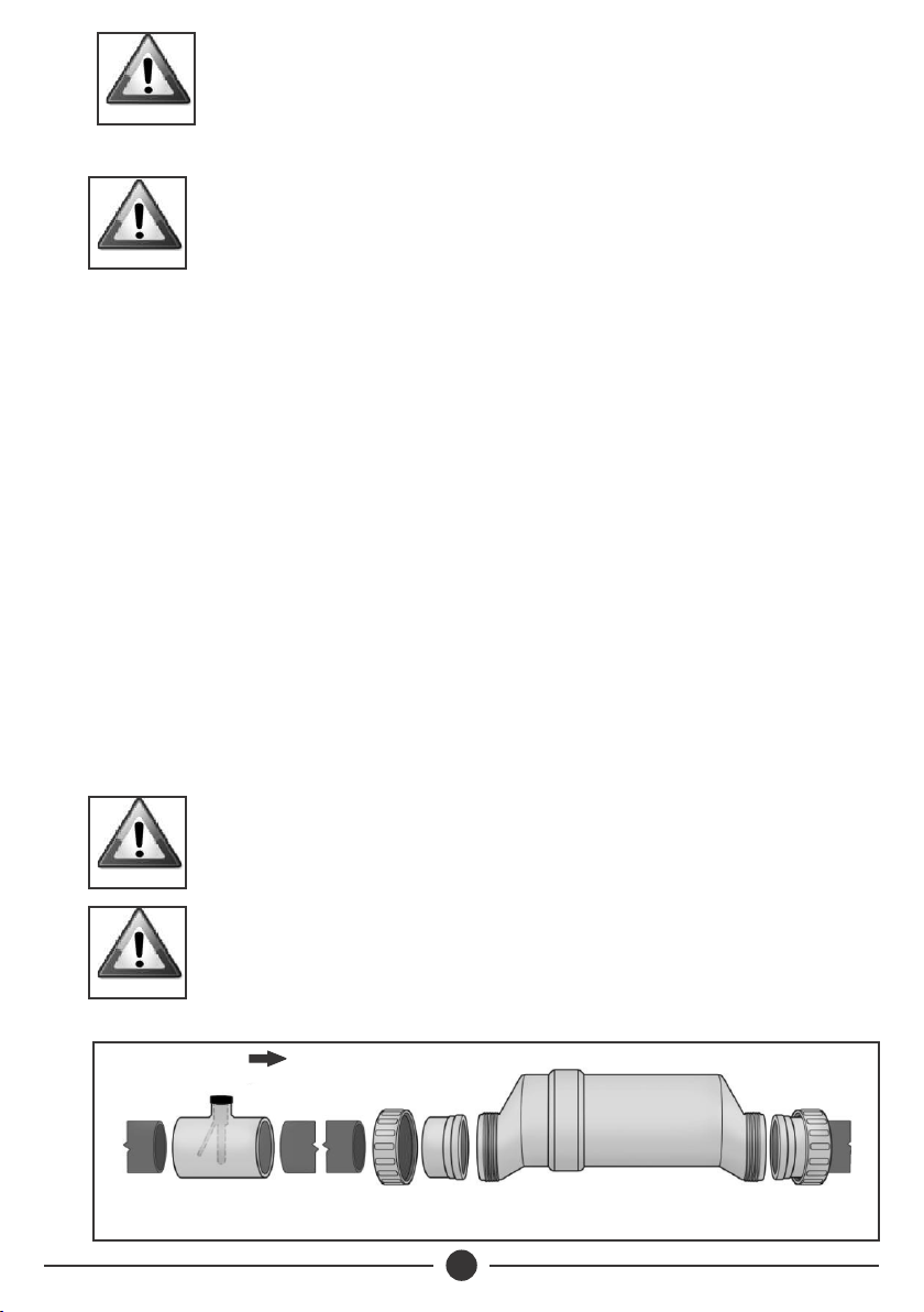
Lay out the equipment to ensure there is enough pipe space available.
ŸWhen positioning the Flow Switch, ensure at least 30cm of straight pipe
before the Flow Switch. If installed after the Electrolytic Cell, the Cell
provides this space. The raised arrow on the black plastic cap must be
pointed in the direction of water flow as it returns to the pool. If installed
horizontally, ensure that the wire-side faces upwards. The Flow Switch is
approximately 100mm in length; a typical gap required is 30mm.
ŸWhen positioning the Cell, consider the side of the cell with the cord as
the "inlet" side. If installed horizontally, ensure that the wire- side faces
upwards. From end to end, the Cell with both unions is approximately
40cms length; a typical gap required is 35cms.
To ensure proper operation, verify that the arrow on the
flow switch (located on the side) points in the same
direction of water flow.
CAUTION
Flow Switch
Double-check that all Cell and Flow Switch cables can
reach the Control Panel.
CAUTION
For installation with 1 ½” plumbing, use 2” to 1 ½”
reducer bush with flow switch, and use alternate 1 ½”
Cell Unions; be sure to note any new or additional
measurements before cutting pipe.
CAUTION
3
1
Water Flow
Fig 2 2
Ensure that the pool pump and all AC power is turned
off before installation.
CAUTION

7
This portion is threaded and may be turned during service; additional thread
seal tape may be added if necessary.
2. To install the Cell unions, cut out a section of pipe at the desired installation
location. Clean parts and plumbing with PVC Primer to prepare the pipe
ends and interior of unions. Place the threaded collars over the pipe ends.
Using plumbing Solvent cement, glue one union to the pipe end.
3. Hold the Cell and second union up to the first, to gauge the correct distance
before gluing the second union to the remaining pipe end. Allow sufficient
time for glue to dry.
Ensure that the O-rings are fitted to the unions. Place the Electrolytic Cell
between the unions and tighten the collars onto the Cell. For a watertight seal,
do not over-tighten the collars, and only tighten them by hand.
When using a Variable Speed Pump on a low speed setting, the cell should be
inverted in order to ensure adequate flow & efficient chlorine production, as
shown in Fig 3 below
Flow Switch
Cell
After determining the section of plumbing to install the Flow Switch and Cell,
measure out and mark the selected area.
1. To install the Flow Switch, cut out a section of pipe at the desired installation
location. Use PVC Primer to clean and prepare the pipe ends and interior of
Flow Switch. Using plumbing Solvent Cement, glue the Flow Switch to the
pipe ends. Ensure excess glue does not become affixed to movable parts
within Flow Switch.
To ensure proper operation, verify that the arrow on the
flow switch (located on the black plastic) points in the
direction of water flow. The water flow must depress the
hinged activator inside of the Flow Switch.
CAUTION
Fig 3
8
Control Unit:
The PoolChlor control unit must be mounted a minimum of 1.5m horizontal
distance (or more if local codes require) from the pool/spa. The control is
designed to mount vertically on a flat surface facing downwards. The back of
enclosure also acts as a heat sink (disperses heat from inside the box), hence it is
important not to block the back sides of the control unit.
Overview: Using screws, secure the control unit mounting at a comfortable
level on a wall or vertical support, at least 1m above ground level. Minimize direct
exposure to rain, sunlight, water runoff, and lawn sprinkler systems. As with most
electronics, avoid placing the controls in tightly enclosed spaces to avoid a build-
up of excess heat. For operation, the control unit may be wired in to the pump's
power source so that both turn on and off together, or energized continuously for
use with variable speed pumps (Flow switch will control Cell power but lights will
remain on).
Wiring:
Power must be shut off at the circuit breaker before performing any wiring. Be
sure to follow local and electrical regulations. The system has been designed to
easily wire into typical in- ground pool systems. To provide safe operation, the unit
must be properly grounded and bonded.
Earthing:
A lug used for earthing is attached to the bottom of the Control Unit. The Control
2
Unit must be earthed with an 8mm AWG copper wire to the pool earthing system.
Do not operate unit until all salt is dissolved in pool
water.
CAUTION
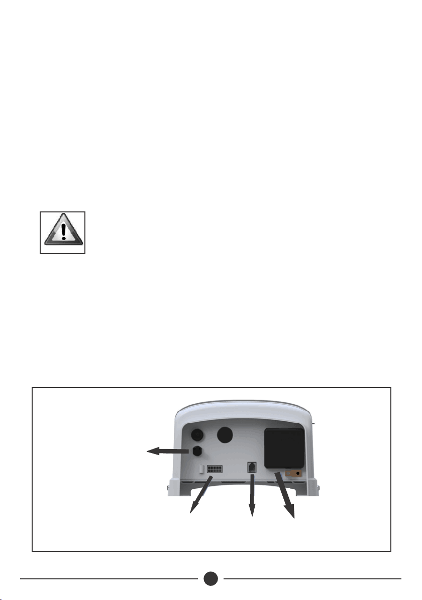
Fig 4
Power Cord
Cell Cable Pump
Connector
Flow Switch
Connector
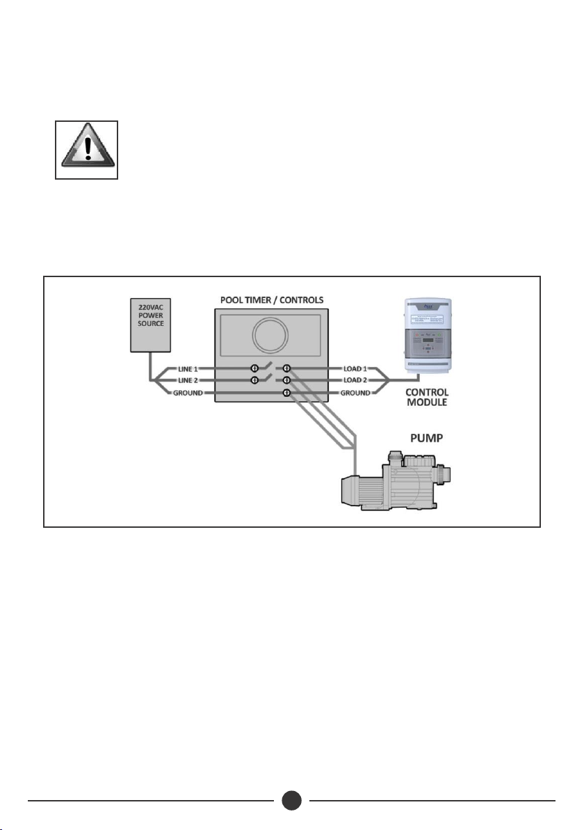
Wiring to Power Source:
The Control Unit comes with an un-terminated Power Cord (AC Input) which is
typically connected to an external timer, which will turn the pump and Control
Unit on and off together. Have the Control Unit wired to the load side of the timer
by a qualified person. See the figure 5 for typical wiring.
9
At this point, equipment installation is complete. If the water has not yet been
prepared then salt should be added to balance water chemistry. Turn the Control
Unit to the Power Off mode until enough salt has been added to the water.
VOLTAGE CONVERSION:
Always double-check the voltage of the power source. Connection to improper
voltage can: a) cause severe damage/harm, or b) cause lights and screen to
power on without system function.
All service should only be done by a person with appropriate electrical skills, with
all equipment disconnected from power.
The unit is shipped from the factory with a 240V
configuration.
NOTE
When used with variable-speed or other electronically controlled pumps, the
Control Unit can be connected directly to the power source. This will allow the
pump to determine when the Cell is energized or dormant by activation of the
Flow Switch.
Fig 5

10
This set of terminal screws can be located inside of the Control Unit, and
accessed by removing the four screws from the Control Unit's aluminum base.
The factory voltage setting is the 240V configuration, with a jumper clip inserted
between the second and third terminals.
INSTALLATION CHECKLIST:
□ Cell unions installed and glued into pipe work.
□ Threaded collars on either side of the Cell are hand tight.
□ Flow Switch is installed and oriented properly.
□ Control Unit is affixed to the wall and wired correctly.
□ Cell cable and Flow Switch are connected to control unit.
□ Checked and confirmed that control unit switches ON and OFF concurrently
with filter pump, or is energized continuously for use with variable speed
pump.
□ Checked all connections and joints for leaks.
□ Sufficient salt has been added and fully dissolved and circulated throughout
the pool water.
□ Pool has properly balanced water chemistry.
Initial Start Up:
Switch on the pool pump (or timer controls). This should activate the system, and
within moments the green LED lights for “Power” and “Generating” should be
illuminated. During this time “No-Flow” light may flash up to 60 seconds as the
pump begins its operation.
To find the optimum Chlorine output setting, start at a setting of 70% and adjust
as needed over the initial start up period. Measure available chlorine in the pool
after two or three days, and adjust the Chlorine output level accordingly.
Fig 6
11
If the available chlorine is too high, lower the Output level; if the available
chlorine is too low, raise the Output level. It will take a few adjustment to find the
ideal setting Once determined, it should only take minor adjustments throughout
the season.
Understanding the operation of the PoolChlor unit will ensure maximum
performance. There are three factors whose control directly contribute to the
amount of chlorine the unit will generate:
1. The chosen percentage of Chlorine output.
2. Hours of pump run- time each day.
3. Water chemistry balance, including the amount of salt in the pool, and
chemicals that minimize chlorine demand, such as stabilizer level in the
water. See “Water chemistry” information on page 3.
After making the initial adjustments to the Chlorine Output level, additional
adjustments are only necessary due to changing seasonal temperatures, or
changes in bather load. Ensure that the pump runs long enough each day to
turnover at least twice the pool water volume. This is more than sufficient amount
of time for chlorination of the pool, but if the pool has high chlorine
demand, running the pool pump longer allows for more chlorination. Measure
the water chemistry and chlorine level on a regular basis.
5. EQUIPMENT OPERATION
Fig 7

12
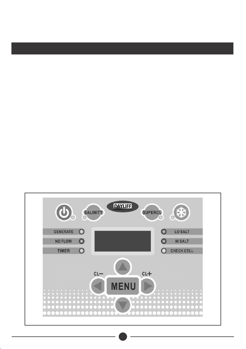
CONTROL BUTTONS:
1. Power: Use this button to manually power the system ON or OFF.
2. Salinity: Displays the average measurement of the most recent salinity levels
in the pool water. The average is constantly being updated by real-time salinity
readings.
When first installed, this reading may display the last
salinity readings taken at the factory. This average will
begin to update with your pool's operation over the first
24 hours.
NOTE
3. Super CL: Temporarily boosts Chlorine output to maximum power for 24
hours, or until power is switched off.
4. Chlorine Output: Use the left/right arrow buttons to raise/lower the
system's power setting and thereby the rate of chlorine production.
5. Select: While in the Menu, the left/right arrows change options for Pool
Temperature, Instant Salinity, and Cell Version.
6. Menu: Press sequentially to cycle through the following information:
1. Pool Temperature (in degrees celsius)
2. Cell Voltage (in many cases 21.0 to 27.0 when chlorine is being
generated, otherwise 16-31V)
3. Cell Current (in many cases 2.50 to 7.80A when chlorine is being
generated, otherwise 0A during normal rest cycles.)
4. Real-Time Salinity reading ( xxxx ppm or x.x grams/Liter.)
5. System ID
6. Software revision level
7. Cell Version.
LED INDICATOR LIGHTS:
Ÿ Power: Located on the Power Button, this LED indicates that the Control Unit
is receiving input power when illuminated.
ŸGenerate: This LED is illuminated during normal operation, and indicates
that the system is able to generate chlorine. When flashing, the pool water is
either too hot or too cold for chlorine generation. This light may be off during
rest periods of the systems’s duty cycle.
ŸSuper CL: Located on the Super CL Button, this LED is illuminated when the
Super CL mode is active.
ŸRemote: This part is controlled by a remote control system.
13
Using the Power Button to turn the system OFF does not
remove power from the control box. Always disconnect
power at the circuit breaker prior to attempting any
service procedure.
CAUTION
ŸSalinity: Located on the Salinity button, this LED is illuminated when the
button has been pressed to display the salt level reading.
ŸNo Flow: This LED is illuminated when the Flow Switch has detected no flow.
This causes the Cell to stop generating chlorine. A flashing LED indicates that
the flow is restored, but there will be a 60 second delay before generation is
reestablished.
ŸLo Salt: When this LED is flashing, the salt level is near to its minimum
threshold, which is causing the Cell to operate at low efficiency. When this
LED is illuminated steadily, the salt level is too low and Cell has shut down.
The salt level must be raised before operation is restored. See "Adding Salt"
for more information.
ŸHi Salt: When this LED is flashing, the salt level is higher than necessary.
When this LED is illuminated steadily, the salt level is too high and the Cell has
shut down. The pool water must be diluted with fresh water before operation
is restored.
ŸCheck Cell: When this LED is illuminated, Cell efficiency is greatly reduced,
or it is time for regularly scheduled Cell inspection. When illuminated, the
Cell has stopped producing chlorine. The Electrolytic Cell should be
inspected and cleaned (if necessary). Switch off power from the system, and
inspect the Cell. If mineral build-up is present, clean Cell according to the
instructions on page 15. If after inspection, the Check Cell light is still on after
restoring power to the system, then cleaning is necessary even if mineral
build-up wasn't immediately visible to the eye. If illuminated after cleaning,
Cell replacement may be necessary. This light takes priority over any salinity
indicators.

14
6. MAINTENANCE
To maintain maximum performance, it is recommended that the Cell is removed
and visually inspected at least every 3-4 months. The unit will indicate at the
appropriate time by flashing the “Check Cell” LED.
After inspecting the Cell and cleaning, if necessary press and hold the System
Status button next to the display for 5 seconds to reset the flashing “Check Cell”
LED.
The Electrolytic Cell has a self-cleaning feature incorporated into the electronic
control's logic. In most cases, this self-cleaning action will keep the cell working at
optimal efficiency and help to inhibit mineral build-up. In areas with very hard
water (high calcium and/or mineral content), and in pools with poor water
chemistry, the cell may require more frequent cleaning (see below). If the “Check
Cell” LED remains on after a thorough cleaning, it may require additional
cleaning, or the cell may be at the end of its life cycle and may require
replacement.
Maintaining the Electrolytic Cell:
As a natural result of the electrolytic process which creates chlorine from salt
molecules, a white mineral build-up is attracted to the titanium plates in the Cell.
The self-cleaning feature helps to inhibit such build-up and scaling. However, the
attraction of minerals is inevitable, and eventually they should be removed. The
Control Unit will illuminate the " Cell" light when such cleaning is necessary.
With correct water chemistry, the Cell will typically only need cleaning once or
twice a season.
When removing the Cell for cleaning or replacement:
1. Turn off all power, close return line valves if applicable.
2. Unplug the cell cable connecting the Cell to the Control Unit.
3. Unscrew threaded collars around the PVC piping that connect the Cell to the
return line plumbing.
4. Pull entire Cell away from the Unions.
DO NOT pull or hold the Cell by its cable.
CAUTION

15
To clean the Cell of mineral buildup:
1. Attach Cleaning Cap (sold separately) and orient the Cell vertically. Place on
the ground and stabilize so as to remain upright and prevent spilling.
2. In a separate bucket, mix one part Hydrochloric acid into four parts
water. Pour this weak acid solution directly into Cell. Ensure that the cleaning
solution COMPLETELY fills the inside of the Cell.
3. Allow solution to soak for NO MORE THAN TEN MINUTES.
4. Properly dispose of acid solution and use a hose to generously rinse the Cell.
5. Reinstall Cell into PVC return line.
If mineral build-up is severe, more than one cleaning
may be necessary to dissolve remaining solids.
Cleaning the Cell is only necessary to remove an
excessive build-up of minerals on the plates. A light
coating of minerals does not impede performance.
Excessive cleaning will reduce lifespan of the cell. If
submerging entire Cell assembly, do not allow Cell
cable to be covered by liquid.
CAUTION
When cleaning the Cell always wear adequate
protection, such as rubber gloves and eye protection.
Always add acid to water, do not add water to acid.
Always work in a well-ventilated area. Splashing or
spilling acid can cause severe injury and/or property
damage.
CAUTION
Start-up:
When opening the pool after a period of inactivity, do not power on and use the
chlorine generator until the pool's water chemistry has been balanced and
brought to ideal levels.
Replacing the Cell:
When the titanium blades inside the Electrolytic Cell have reached the end of
their lifespan, replacements are available so that the whole system does not have
to be removed. Replacements are easily switched out. To ensure quality and
value, only genuine replacement parts may be used. Bypass cells are available,
and may be used to continue to run water through the plumbing without the
Electrolytic Cell in place.

16
HELPFUL NOTES:
Proper operation of the chlorine generator can be easily verified by checking the
lights on the control panel. However, if the pool remains cloudy, or the chlorine
residual tests low, then the chlorine being produced is being lost due to high
chlorine demand or improper water conditions.
To reduce the chlorine demand, check the pH and Stabilizer (Cyanuric Acid)
reading. Check for phosphates and nitrates, which commonly contribute to
severe chlorine demand. If tests show positive, then a shock treatment with an
oxidizer agent is advised. Generally, superchlorination is not necessary if the pool
is maintained at correct levels.
Recommended List:
ŸRead and keep this manual in a safe place.
ŸIncrease Chlorine Production when temperature increases.
ŸIncrease Chlorine Production when number of bathers increases.
ŸUse Stabilizer to prevent chlorine dissipation by the sun.
ŸMount Control Unit in shade or out of the direct sunlight whenever possible.
ŸDecrease Chlorine Production when temperature decreases.
ŸTake pool water sample to a Pool Professional at least once per month.
Not Recommended List:
ŸDo not allow fertilizer anywhere near your pool. Fertilizers are one of many
sources that contain Nitrates or Phosphates which cause severe chlorine
demand in pool water.
ŸNever use dry acid to adjust pH. A build-up of by-products can damage the
Cell.
ŸDo not add any pool water balancing chemicals (including salt) unless the
Control Unit is turned off.
ŸDo not add any chemicals including salt to the skimmers.
ŸDo not let salinity level drop below 3000 ppm.

17
Problem Solution
7. TROUBLE SHOOTING
Check input power is connected to the control. Be sure the jumpers
are set properly. Verify input voltage with a voltmeter.Check fuse if
blown. The board is protected by a 20 amp fuse located on the
circuit board above the cell connector.
“Power” LED
not on
The temperature of the pool water is too high or low to operate.
You can override this by Pressing button SUPER CHLORINATE. The
chlorinator will run at maximum output for the remainder of the
current pump cycle or 24 hours, whichever comes first.
“Generating”
LED flashing
The chlorinator has sensed a no flow condition and has stopped
generating chlorine. Check that the flow switch is plugged into the
connector on the bottom of the control unit and that the wire is not
cut or damaged. Make sure there is at least 30cms of straight pipe
before the flow switch. If there is adequate flow and the LED is still
on, check that the arrows on the flow switch are pointing in the
direction of flow. If the light is flashing, the flow is established and
t h e c h l o r i n a t o r w i l l t u r n o n w i t h i n 1 m i n u t e .
“No flow”
LED
illuminated
or flashing
Check salt level in pool. If salt level is low, add salt according to
chart on page 5. Before adding large quantities of salt, it is
advisable to have your salt level professionally checked.
“Check Salt”
LED
illuminated
or flashing
Check salt level in pool. If salt level is too high, lower salt level by
draining some of the pool water out of the pool and replace with
fresh water. Continue until the salt concentration is at
recommended levels.
“High Salt”
LED
illuminated
or flashing
This manual suits for next models
1
Table of contents
Other DAYLIFF Water Filtration System manuals

Popular Water Filtration System manuals by other brands


CAS
CAS Talline Installation & operating instructions

Terra Universal
Terra Universal WhisperFlow 6601-24A-UR-220 product manual

Waterite
Waterite VECTAPURE RSX II Operator's manual

ATOMSTACK
ATOMSTACK MAKER instructions

Acqua Brevetti
Acqua Brevetti BravoFIL Plus Installation and operating manual

elysator
elysator PUROTAP profi 1 Series operating instructions


