CAS Talline Manual

INSTALLATION & OPERATING
INSTRUCTIONS
MODEL: TL RANGE
s a l t w a t e r c h l o r I n a t o r
Talline

Designed and manufactured in Australia
TABLE OF CONTENTS
1. Important Warnings and Safety Instrucons................................................................................................3
1.1 Important Warnings....................................................................................................................3
1.2 Important Safety Instrucons.....................................................................................................3
2. General Overview...........................................................................................................................................4
2.1 Recommendaons and Helpful Hints.........................................................................................4
2.2 Contents .....................................................................................................................................4
2.3 Tools Needed...............................................................................................................................4
3. Pool Preparaon............................................................................................................................................5
4. Power Pack & Cell Electrode Installaon.......................................................................................................6
4.1 Power Pack Installaon...............................................................................................................6
4.2 Cell Electrode Installaon...........................................................................................................6
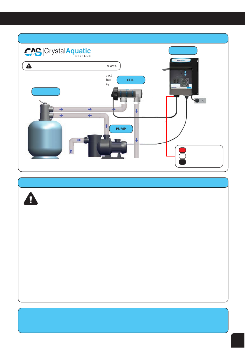
4.3 Installaon Diagram....................................................................................................................7
5. Power Pack Operaon....................................................................................................................................8
5.1 Timer Switch...............................................................................................................................8
5.2 Cell Switch...................................................................................................................................8
5.3 Circuit Breaker.............................................................................................................................8
5.4 AC Socket (Pump Outlet).............................................................................................................8
5.5 Juncon Box................................................................................................................................8
5.6 + and – Buons ...........................................................................................................................8
5.7 Output LEDS's.............................................................................................................................8
5.8 Direcon LED...............................................................................................................................9
5.9 Water Flow LED...........................................................................................................................9
5.10 Salt Test......................................................................................................................................9
5.11 Start Up Procedure.....................................................................................................................9
6. Timer Seng................................................................................................................................................10
7. Water Chemistry..........................................................................................................................................12
8. Chlorinator Maintenance.............................................................................................................................14
8.1 Inspecng and Cleaning the Power Pack..................................................................................14
8.2 Inspecng and Cleaning the Cell Electrode...............................................................................15
9. Chlorinator Troubleshoong........................................................................................................................16
10. Specificaon Table.......................................................................................................................................18
11. Warranty......................................................................................................................................................19
12. Technical Support........................................................................................................................................20
Talline

3
1.IMPORTANT WARNINGS & SAFETY INSTRUCTIONS
1.2 Important Safety Instrucons
To reduce the risk of injury, do not permit young children to use this product unless they have
been trained by the person responsible for their safety and they acknowledge their ability to use
such equipment. To reduce the risk of accidents or incidents, service on the unit should only be
performed by a qualified pool service professional.
When mixing acid with water, ALWAYS ADD ACID TO WATER. NEVER ADD WATER TO ACID.
DO NOT PLUG UNIT IN IF CARTON HAS BEEN WET.
CHLORINE GAS BUILDUP CAN OCCUR WITH IMPROPER WIRING: To reduce the risk of personal
injury the Power Pack is designed so that the Electrolyc Cell will only receive power when the
pool pump is on. Otherwise, dangerous chlorine gas build–up can occur. If the pump is not
installed to the AC Socket (pump outlet) on the Power Pack then the installer must ensure that
the Electrolyc Cell is never energised when the pool pump is OFF or water is not flowing
through the unit.
1.1 Important Warnings
This manual contains important informaon about the installaon, operaon and safe use of
this product. This informaon should be given to the owner and/or operator of this equipment.
When installing and using this electrical equipment, basic safety precauons should always be
followed. Failure to follow safety warnings and instrucons in this manual can result in serious
injury and/or damage to your equipment. Read and follow all warning noces and instrucons
which are included in this manual.
The Power Pack internally contains live components. There is a danger of electric shock if
opened. If the power cord is damaged then it should be replaced by the manufacturer, their
agent or similar qualified person, in order to avoid a hazard. The product shall be installed
according to AS/NZS 3000 wiring rules. It shall be installed outside the pool zone.
E
~
Should you require further information
visit www.crystalas.com

4
2. GENERAL OVERVIEW
Congratulations on your recent purchase of your Talline™ Salt Water Chlorinator. Please take a
moment to read through the entire manual before installing your new unit. Your chlorinator
must be installed and operated as specified.
While every effort has been made to ensure that the information contained in this guide is accurate and
complete, no liability can be accepted for any errors or omissions. Crystal Aquatic Systems reserves the
right to change the specifications of the hardware and soware described herein at any time without
prior notice.
Please remember that your Talline™ Salt Water Chlorinator is not designed to chemically maintain your
pool water and keep it balanced, but rather to produce chlorine from a mild salt solution within the
water. We encourage regular water testing, balancing and correction if & when required to
maintain the recommended balanced levels of your pool water. This is a vital part of a complete
maintenance program and will ensure trouble free performance as well as a healthy and sparkling clean
pool.
The Talline range is a reverse polarity model known as TL, which is a reversing design and automatically
changes direction every 5 – 10hrs (depending on your seng). This change of polarity causes the calcium
to dislodge and keep the cell plates clean. Please note occasional cleaning of the electrode plates may be
necessary.
2.1 Recommendaons and Helpful Hints
• Read and keep your manual in a safe place.
• Increase chlorine producon when temperature goes up.
• Increase chlorine producon when number of swimmers increases.
• Use (Cyanuric Acid) Chlorine in Pool.Stabiliser to stabilise
• Decrease producon when temperature goes down – (during winter).
• Take pool water sample to your pool professional at least twice a month.
2.3 Tools Needed
Drill with 7.0mm drill bit
Basic PVC fittings
Hacksaw No.2 Phillips head screwdriver
PVC Primer
and Glue
2.2 Contents
2x green wall
plugs with screws
Talline Cell Housing & Electrode
2x50/40
Reducing Bushes
The Installation & Operating
Instructions
Talline Power Pack

3. POOL PREPARATION
5
Before operating your Talline™ unit please read the following:
Handy Tips
•Check your salt levels with your local pool professional before installing your unit.
• 5 – 4 5Salt levels should ideally be 3 00 500ppm and no more than 000ppm.
•NEVER ADD SALT DIRECTLY TO THE SKIMMER BOX. This high concentraon of salt will
pass through your filtraon, pump and other pool equipment.
•Salt levels above 4000ppm may overload the unit and cause excessive heat.
•For all new pool installaons please seek advice from your pool builder before adding
salt as some new surfaces request no salt to be added when inially completed.
• The colder the water the lower your output but this does not mean you need more salt.
There will always be less chlorine demand in colder water.
• We recommend 3.5kg per 1000 litres (1 cubM) of pool water and a 50 000 litre (50 cubM)
new pool needs approximately 175kg of salt.
• The unit can operate on mineral/magnesium chloride salts and you should allow an extra
20 – 30% on the ppm for these type of salts.
• Salt should always be added to the shallow end of the pool and allowed to dissolve.
Do not let the salt sele on the floor of the pool as this may cause damage to the surface.
Use your pool brush to mix the salt into the water.
• Running the pump will mix the water and help the salt to dissolve.
• Only run the pump in the first 8 – 12 hours (ensure the cell is switched off) to allow the salt
to dissolve.
• If you press the + buon unl you reach the top LED (no. 8) then let go and wait for the
output to sele then if all 8 LEDs are on then there is enough salt if it does not reach the
top 8th LED then you either need salt or if the cell is old it may need replacing.
Should you require further information
visit www.crystalas.com

4. POWER PACK & CELL ELECTRODE INSTALLATION
6
4.1 Power Pack Installaon
•The Talline™ Power Pack has a Ingress Protection Range of IP23 enabling it to be installed
outdoors. Regulations require that the Power Pack shall be installed outside the pool zone.
• The Power Pack shall be installed according to AS/NZS 3000 wiring rules.
• The Power Pack should be installed in a well venlated posion ideally away from sunlight
and rain to prolong life and at least 1m above ground to prevent run off water entry.
• Ensure that the Power Pack is not stored near chemicals, ferlisers or in a closed
unvenlated shed with similar products as the fumes will cause excessive corrosion and
damage to the Power Pack and Control Board.
• When mounng the Power Pack on a post it is recommended to install a flat panel at least
the size of the Power Pack to act as a waterproof backing plate.
• Mount the Power Pack with the Green Plugs and Mounng Screws provided.
The Power Pack should be mounted no further than 1.5 metres from the Chlorinator Cell,
for ease of operaon of the controls on the Power Pack.
4.2 Cell Electrode Installaon
• Connect the Cell Housing horizontally in the return line to the pool (use reducing bushes
supplied if 40mm PVC pipe) using high pressure PVC glue. The Cell Housing can be mounted
vercally but provision must be made for a gas trap.
• Direcon of water flow though the Cell Housing is not crical although we do recommend
entry from the closed end of the Cell Housing and exit from the end closest to the Cell
Locking Ring. The reason is to cause less water hammer over me on the cell plates.
• Check that the O-ring is clean, greased with silicone grease (DO NOT use petroleum based
jelly) and securely located in the Cell Housing.
• Fit the Cell Electrode and ensure Cell Locking Ring is firmly ghtened by hand (DO NOT use
a tool to ghten).
• Connect the leads from the Cell Electrode to the Juncon Box under the Power Pack
ensuring the colours match that indicated on the Juncon Box (RED – closest to the front,
WHITE – in the middle and BLACK – closest to the rear).
• Plug the Power Pack 3 pin plug into a suitable weatherproof RCD protected 10amp outlet
and then plug the pump into the 3 pin AC Socket located at the boom of the Power Pack.
Should you require further information
visit www.crystalas.com

7
4. POWER PACK & CELL ELECTRODE INSTALLATION
Important Notes
•The pump rang must not exceed 8amps.
• Saltwater may damage Juncon Box and electrical components in the Power Pack.
•DO NOT use a drill to ghten Juncon Box screws – this may strip them – use a hand
held screw driver.
WARNING:
• We DO NOT recommend the use of valves on the inlet or outlet of the cell housing. If you
do use a valve then it is important to ensure that the valve cannot deadhead (lock closed)
while the pump is running. It is the installers responsibility to ensure some form of flow
control is installed in this instance and it disables the pump.
•ALWAYS ensure that pipe work and equipment do not allow gases generated from the cell
to collect and build up in any part of the installaon.
• It is RECOMMENDED that the Cell Housing be installed horizontally to create a natural gas
trap that acts as a safety device. Installaon in any other way may cause explosion, injury
or death if the installer does not allow for gas removal.
• The Cell Housing must be installed in the RETURN pipework to the pool. It must always be
installed aer the filter, gas heater, solar heang or heat pump.
•DO NOT apply priming fluid to the Cell Housing, it is not needed and may react with the
plasc.
PUMP
RETURN
TO POOL
FROM
SKIMMER BOX
4.3 Installaon Diagram
WARNING: DO NOT plug in if carton has been wet.
CELL
FILTER
Water turbulance has less impact
on plates with entry this end but
Cell can be plumbed either way.
POWER PACK
Ensure
good
venlaon
POWER
OUTLET
Make sure
that screws
are ght on wires
and colours match.
Red: Closest to front
White: Centre
Black: Closest to rear
Should you require further information
visit www.crystalas.com

5. POWER PACK OPERATION
8
5.1 Timer Switch
This switch posion determines whether the unit is manually turned on or automacally
controlled by the Timer.
•Auto Posion – the me clock controls the operang hours. See secon 6 for Timer Seng.
• Manual Posion – the unit is on and both the pump AC Socket and Cell will be powered up.
5.2 Cell Switch
This switch posion determines whether the Cell is turned on or off when power is supplied to
it from the above Timer Switch.
•OFF Posion – even if the Timer Switch is powered on there will sll be no power to the Cell.
•ON Posion – if Timer Switch is powered on then there will be power to the Cell.
•Changing Direcon – while the unit is running you can change direcon by turning off the
Cell Switch, wait 3 seconds then turn it on again. The direcon should change. If it does not
then repeat this again and it should change direcon.
5.3 Circuit Breaker
A Circuit Breaker is an automacally operated electrical switch designed to protect an electrical
circuit from damage caused by overcurrent, overload or short circuit. It can be reset by pressing
the buon in aer it has tripped. It may be damaged if you supply excessively high levels of salt
through the Cell.
5.4 AC Socket (Pump Outlet)
The AC Socket allows the pump to be electrically operated and controlled by the Power Pack.
WARNING: If you fail to control the pump this way then you must allow for a flow switch
mechanism to control the electrical supply to the Power Pack, so as to prevent gas build up if the
pump stops.
5.6 + and – Buons
Simply press the – Buon and the chlorine producon will automacally decrease by
approximately 15%. Press the + Buon and the chlorine producon will increase by
approximately 15%. When all green LED Output Lights are on this indicates 100% output.
5.7 Output LEDS’s
There are 8 Output LED’s on your Talline display. Each one of the LED’s indicate the
chlorine production output.
5.5 Juncon Box
The Juncon Box allows recfied DC voltage to be coupled to the Cell. This is where the Cell
cable is connected to the Power Pack.

9
5. POWER PACK OPERATION
5.8 Direcon LED
Above the timer is a Direction LED indicating the Cell Electrode direction at that particular
time. Solid Green indicates Forward and Flashing indicates Reverse. The reversing times
can be changed from 5 to 7.5 and 10 hours, please contact your local Crystal Aquatic
Systems agent for assistance.
5.9 Water Flow LED
A Water Flow sensor comes standard with your Talline unit. If flashing Red this indicates
insufficient flow of water in the cell housing or a fault. Contact your local Crystal Aquatic
Systems agent for assistance.
5.10 Salt Test
Salt Test allows you to check if the salt levels are correct, be pressing the + Buon and
holding it for 5 seconds. All 8 Output LED’s indicate salt levels are correct and if they do
not reach 8 then salt levels need to be checked or contact your local Crystal Aquatic
Systems agent for assistance.
5.11 Start Up Procedure
• Ensure 10amp wall outlet supply switch is turned "OFF".
• Cell Switch in the "OFF" posion.
•Timer Switch in the "MANUAL" posion.
•Turn the 10amp wall outlet supply switch "ON".
•The pump should start up and prime.
Allow the pump to run for 2 minutes and repair any leaks if needed• .
• Turn the Cell Switch to "ON" unl all 8 Green LED’s light up.
•Set the Timer to run 6 – 10 hours in the summer and 3 – 6 hours in the winter. Refer to sec. 6
Timer Seng for further details.•
•Now turn the Timer Switch to "AUTO" and leave it here to run automacally.
All Talline ™ Self Cleaning models are controlled by a Micro-Chip controller
that performs several funcons, including the change of current direcon and
water sensing.

6. TIMER SETTING
10
Your Talline™ unit comes with a simple to operate quartz mechanical Timer which has a built
in baery back up function.
This area of set up is crical and we recommend you take me to read it and understand why we
recommend certain sengs.
Obviously sunlight and higher bather loads in summer dissipate more chlorine than in winter.
That is why you need to check your chlorine reading regularly and adjust your sengs when
required.
It is recommended to run the unit for 2 periods every day (early morning and evening) when the
sun extracts the least amount of chlorine from the pool, giving it me to do its work.
Winter Sengs
In winter you should lower your running me by up to 50% of your summer seng depending on
your free chlorine levels. You should ideally run 2-3 hours in the morning and 2-3 hours in the
evening. This preserves and extends the life of your equipment.
Important Notes
The Timer Switch will override the Timer when it is in the Manual posion. For mer sengs to
control the unit the Timer Switch needs to be in the AUTO posion.
WARNING:
ALWAYS TURN THE CLOCK FACE CLOCKWISE NEVER ANTI – CLOCKWISE. You will strip plasc
gears and damage the Timer.
Summer Sengs
Ideally, run for 4 hours in the morning (6 – 10am) and 4 hours in the evening (4 – 8pm).
For a smaller pool you can run less hours. In extreme weather it may be necessary to run longer
hours.
Should you require further information
visit www.crystalas.com

11
6. TIMER SETTING
To adjust the me of the clock, simply hold the outside of the white segments and
turn the dial unl the clock reads the right me and the number near the mer
on/off arrow is close to the same number.
Your Timer is simple to use, easy to understand and a reliable well known design.
It has a baery back up funcon if you operate your pool equipment from a low
tariff supply that turns off at mes. It does require at least 12 hours charging at
first but simply leave it alone and it will charge itself as required.
This me is set at 8:00am and the dial pointer shows
the 8:00 posion as does the clock face hands
The Timer comes on where the pins that are pressed
out reach the White dial pointer (in this case it will
be from 6 – 10am and 4 – 8pm)
With White Lever in this posion Power Pack is OFF
With White Lever in this posion Power Pack is in
AUTOMATIC and the mer seng turns it ON/OFF
When White adjustable segment pins reach this
dial pointer (in AUTOMATIC posion)
the Power Pack turns: if pins pressed out ON
With White Lever in this posion power pack is ON
if pins pulled in OFF

7. WATER CHEMISTRY
12
The Talline™ unit is designed for use with swimming pool water balanced in accordance with the
Langelier Satura on Index with a pH range of 6.8 – 7.8.
As previously advised, for best performance and operation of your Talline™ unit, certain water
balances must be maintained within your swimming pool. Have your water tested regularly.
Transport the test water in an opaque container and have the test done as soon as possible for the
most accurate results. What follows is a list of recommended water chemistry levels.
7.1 Chlorine
Ideal Chlorine (Free Chlorine) Levels: 2 – 3ppm (2 – 3mg/L) and no more than 4ppm (4mg/L).
Adjust the chlorine output by pressing + Buon to increase and – Buon to decrease. Running the unit
for longer or shorter hours can achieve the same result.
Measurement Interval: Once a week
7.2 Salt
Ideal Salt Levels: 3500 – 4500ppm and no more than 5000ppm.
Although salt is not consumed by the Chlorinator, salt is lost during backwashing, pool overflow,
splashing and on bathers that use it. The correct salt level allows for the most efficient producon
levels and electricity consumpon.
The salt level SHOULD NOT go below 3000ppm. Operang the unit with too lile salt in the pool will
cause damage to your Cell.
Salt is the essential element by which your unit operates. Not enough salt means not enough
chlorine – this simple rule governs the total operation of your Talline™ unit, and insufficient salt will
damage your Cell.
The unit will operate with good stability on higher salt levels but it is sll advisable to run at the correct
level to prevent damage. Salt levels above 5000ppm may overload the unit and cause excessive heat.
Measurement Interval: Every 4 – 6 weeks
Important Notes
•NEVER ADD SALT DIRECTLY TO THE SKIMMER BOX. This high concentraon of salt will pass
through your filtraon, pump and other pool equipment.
•HANDY TIP 1: When all green LED Output Lights are on this indicates 100% output. DO NOT ADD
ANY MORE SALT.
•HANDY TIP 2: If the + Buon has been pressed to the top and all Green LED Output Lights do
not reach 8, then salt levels need to be checked or contact your local Crystal Aquatic
Systems agent for assistance.
• The colder the water the lower your output but this does not mean you need more salt. There
will always be less chlorine demand in colder water.
• We recommend 3.5kg per 1000 litres of pool water and a 50 000 lt new pool needs
approximately 175kg of salt.
• The unit can operate on mineral/magnesium chloride salts and you should allow an extra
20 – 30% on the ppm for these type of salts.
• Salt should always be added to the shallow end of the pool and allowed to dissolve. Do not let
the salt sele on the floor of the pool as this may cause damage to the surface. Use your pool
brush to mix the salt into the water.
• Running the pump will mix the water and help the salt to dissolve.
• Only run the pump in the first 8 – 12 hours (ensure the Cell is switched off) to allow the salt to
dissolve.
•Low salt levels (<1500ppm) will destroy the coang on the Cell and void the warranty.

7. WATER CHEMISTRY
13
7.4 Total Alkalinity
Measurement Interval: Every 4 – 6 weeks
Ideal Total Alkalinity Levels: • Concrete Pools: 80 – 150ppm
• Fibreglass/Vinyl Pools: 80 – 120ppm
Total Alkalinity should not be confused with pH, although the two are closely related. Total
Alkalinity determines the speed and ease of pH change, it is measured in ppm. You should
use a test kit which includes a test for Total Alkalinity. Low Total Alkalinity can cause unstable
pH levels. This causes an inability to keep the pH constant and may cause staining, etching
and corrosion of metals. High Total Alkalinity will cause constantly high pH levels.
• When Total Alkalinity is high you can add hydrochloric acid (a lile at a me) to lower the
Total Alkalinity.
• When Total Alkalinity is low you can add sodium bicarbonate ( ) to raise buffer/baking soda
the Total Alkalinity.
7.5 Calcium Hardness
Measurement Interval: Every 3 months
Ideal Calcium Hardness Levels: • Concrete Pools: 250 – 300ppm
• Fibreglass/Vinyl Pools: 150 – 190ppm
In addion to pH and Total Alkalinity, Calcium Hardness must be kept in balance so that your
pool water does not become too corrosive or end up scaling the surface of your pool. These
are symptoms of swimming pool water that is unbalanced.
7.6 Stabiliser
Measurement Interval: Every 4 – 6 weeks
Ideal Stabiliser Levels: 30 – 70ppm
The importance of pool Stabiliser cannot be over emphasised. It is essenal in helping retain
chlorine in your pool. Chlorine is rapidly dissipated by sunlight and the use of Stabiliser will reduce
this dissipaon dramacally. Without Stabiliser, it may be necessary to run the unit for longer
hours.
THE MOST IMPORTANT NOTICE AND WARNING
Only add chemical in the method and quanes as indicated on the packaging provided or advised
by your local pool professional. Also, if in doubt of any results you achieve then do not hesitate to
consult with your local pool professional.
7.3 pH
Ideal pH Levels: • Concrete Pools: 7.4 – 7.6
• Fibreglass/Vinyl Pools: 7.0 – 7.2
A pH of 8.0 makes your chlorine only about 26% efficient so that is why it is crical to keep
your pH in range.
A correct pH level must be maintained to prevent problems such as black spot, staining, cloudy
water, etc. An incorrect pH level can damage the surface finish and walls of your pool.
• When pH is high you can add hydrochloric acid to lower the pH.
• When pH is low you can add sodium carbonate (soda ash) to increase the pH.
Measurement Interval: Once a week

8. CHLORINATOR MAINTENANCE
14
Maintenance of your Talline™ Salt Water Chlorinator is simple and a saltwater chlorinator
has to be one of the most productive pieces of equipment on your swimming pool so it
requires some basic maintenance.
While water chemistry will always be the most important form of maintenance there are also
other hints and pointers to take note of.
•DO NOT cover the Power Pack with towels or similar. There are vents that could be closed
and these need air to keep the unit cool.
• To extend the life of your unit we always recommend installaon in an under cover area
away from the elements.
• Placing the unit in a closed shed or similar environment with chemicals, ferlisers and
other corrosives will damage the unit and could void your warranty.
• Keep the chlorinator off at all mes during backwash cleaning of your filter by turning the
Cell Switch to the OFF posion. Please remember to turn it on once done and return the
unit to AUTO mode.
• Check that the Power Pack Juncon Box screws are ght and cell leads are in sound
condion at least once a year.
8.1 Inspecng and Cleaning the Power Pack
Lile or no maintenance is normally required with the Talline™ Chlorinator Power Pack.
Ensure the Power Pack 3 pin plug plugs into a suitable weatherproof RCD protected 10amp
outlet. Ensure that the pump plugs into the 3 pin AC Socket located at the boom of the Power
Pack. Check all plugs and cords for damage. If damaged then it should be replaced by the
manufacturer, their agent or similar qualified person, in order to avoid a hazard.
If the chlorinator is to be hard wired, then a qualified electrician must complete the installaon.
The Talline™ Chlorinator Power Pack has small air vents to allow internal components to
remain cool in hot weather. The Talline™ Chlorinator has a special oil spray applied to the
inside of the unit during production to stop the insects from entering the unit. To help assist
in keeping the insects away, apply a surface spray periodically on the wall or post that the
unit is mounted on. DO NOT spray directly into the Power Pack and make sure the power is
off when you spray. Allow adequate time for the spray to dry before turning power on again.
Should you require further information
visit www.crystalas.com

8. CHLORINATOR MAINTENANCE
15
8.2. Inspecng and Cleaning the Cell Electrode
Reverse Polarity cells (TL models) should not normally require cleaning, however, in areas
with very hard water all calcium may not be removed. A calcium deposit might form on the
lower areas of the cell, the sensor or the sides of the cell plates. This will NOT affect the
operation of your chlorinator.
All salt chlorinator cells must be cleaned before scale/calcium builds up to the point where the
electrode gaps in the Cell are bridged. If the Cell has excessive calcium deposit, this may damage the
electrode coang, as the bridging causes rubbing on the plate coang and this will affect the
operaon.
Check the Cell frequently to prevent the accumulaon of pool debris that for any reason may have
by-passed the pool filter, parcularly aer backwashing.
Check that the O–ring is clean, greased with silicone grease (DO NOT use petroleum based jelly)
and securely located in the Cell Housing.
For cleaning, please follow these steps:
•Switch off the wall outlet switch as this ensures the pump and Talline™ unit will not turn
on.
• Unscrew the Cell Locking Ring and remove the electrode for inspecon. If calcium
build–up is present, immerse the electrode in cell cleaning soluon.
• A soluon can be made by mixing 1 part hydrochloric acid to 10 parts of water.
If excessive build up is present a stronger soluon may be used to remove the calcium.
Using 5 parts of water will make a more aggressive soluon but will not damage the Cell.
You can use Cell Cleaning Soluons and if you do then follow the instrucon supplied.
• Allow the cleaning soluon to dissolve the calcium deposits for 10 minutes. Dispose
of the cleaning soluon at an approved Council Depot and never into storm water or
sewage drains.
HANDY TIP: Returning this mix to your pool only returns the calcium you just removed, so
you may be beer off reusing the soluon unl exhausted then disposing of it. Always
store this soluon in a safe method as advised on the container.
• Do not scratch or bend the cell plates in the Cell Housing.
• Ensure that the O–ring is clean, greased and properly seated.
• Rinse the electrode in clean water and re–fit the electrode in the Cell Housing, ensuring
that the Cell Locking Ring is hand ght and secure.
• Turn on the wall outlet switch and the pump and chlorinator will return to the mode it was
in before.
• Turn on the unit and confirm chlorine output and mer sengs on the Power Pack.
WARNING
When mixing acid with water, ALWAYS ADD ACID TO WATER. NEVER ADD WATER TO ACID.
Eye Protecon, mask and gloves should be worn when cleaning the cell.

9. CHLORINATOR TROUBLESHOOTING
16
9.1 Not operang at all – no lights
Not plugged into power point or power point
not turned on
Plugged into power point and turned on but sll
no power
Wall outlet working but sll no power
Check that unit power cord goes into wall
outlet and outlet is turned on
Press Timer Switch to MANUAL
If you have checked all of the above then there
is an internal fault - call for service
Potenal Cause Remedy
Timer Switch in MANUAL sll no lights
Test wall outlet with a working appliance
If you suspect for any reason your Talline™ Chlorinator is not performing
or running as it should be, here are some handy troubleshooting tips that may assist you.
9.2 Not operang at all - some lights
When Timer Switch in MANUAL everything
works but nothing works in AUTO
Circuit Breaker stays out in a tripped state
1. Incorrect seng of Timer – see Timer Seng (sec. 6)
2. Faulty Timer – call for service
1. Press in Circuit Breaker on Power Pack
2. Make sure Cell Switch is ON
Faulty Circuit Breaker – call for service
1. Excessively high salt – check salt and lower it if needed
2. Short across Cell plates – remove Cell and check the
plates for any metal lying across plates
3. Faulty Recfiers, Transformer or Cell cable – call for
service
1. Try pressing the + Buon
2. If green LED's do not increase
3. Check Cell lead connecon at the Juncon Box, repair
if damaged or return for service
Ensure sufficient water flow through Chlorinator Cell
Check that the pump is on and running
Look for air pocket – perform backwash if needed
Check skimmer and pump baskets are clean and
securely ghtened
Check for sucon leaks
Seek advice from a pool professional for any of the above
Potenal Cause Remedy
Cell Switch ON but no LED output display
Circuit Breaker resets but trips again
When in MANUAL only the pump works
Water Flow LED flashing RED - low or no water flow
9.3 + Buon not fully pressed
Green Output LED's not at 100%
Low salt level
Press the + Buon Output should increase
Check salt level (sec. 7.2)
Calcium acts as an insulator and needs to be removed
See Cleaning of Cell Electrode (sec. 8.2)
Winter water temperature can be very low
For every 1°C below 28°C the output can drop 2-3%
Check water flow and ensure a full chamber of water is
passing over the Cell
You may need to backwash your filter
Damaged coang will reduce cell life and reduce output
If all condions are correct then Cell could be at the end
of its life
Cell may need cleaning (sec. 8.2) or the Cell may have
run its life in one direcon
Potenal Cause Remedy
Build up of calcium on the Cell plates
Water temperature is low
Insufficient water flow through the Cell
The Cell could be damaged or at the end of its life
Level low in one direcon but OK in the other

17
9.9 Low or No Chlorine Output
Unit not working correctly
Check Salt guide (sec. 7.2)
Check pH guide (sec. 7.3)
Check Stabiliser guide (sec. 7.6)
Go through Troubleshoong from 9.2
Basic sengs such as Output Control and Timer running
hours need to be checked
Potenal Cause Remedy
9.4 Sign of melng or burning of the Juncon Box
The screws were not adequately ghtened during
installaon
If melted then it will need replacing otherwise
ghten as required
Return for service if melted
Potenal Cause Remedy
9.5 Power Pack only works in one direcon
Faulty Recfiers, Transformer or PCB Return unit for service
Potenal Cause Remedy
9.7 Pool pump outlet not funconing properly or pump always on
Check that pump is plugged into the boom of the
Power Pack and not directly in to the wall outlet
Make sure you are set in AUTO mode and not
MANUAL for normal running
Potenal Cause Remedy
Pump not plugged into chlorinator
9.8 Cell not cleaning, excessive calcium build up on Cell or Power Pack not changing direcon
1. See Calcium Hardness test (sec. 7.5) and adjust
water accordingly
2. Change the Hard/So Switch to HARD (sec. 5.9)
3. Manually try reverse direcon (sec. 5.2 - Cell
Switch Changing Direcon). Failure for this to work
could indicate a faulty PCB - return for service
Potenal Cause Remedy
Excessively high calcium, change of direcon me
set too high or faulty PCB
Salt level is to low
pH is too high
Stabiliser is too low
Cell at the ends of its life
Unit not set correctly
9.10 Timer loses me when mains power removed
Baery life expired Replace Timer - return for service
Potenal Cause Remedy
9.6 Timer is not funconing properly
Make sure Timer Switch is set to AUTO and White
Lever in the centre of Timer is set to me clock
posion and not "I" or "O"
Refer to Timer Seng in this manual (sec. 6)
Potenal Cause Remedy
Incorrect Timer sengs
9. CHLORINATOR TROUBLESHOOTING

10. SPECIFICATION TABLE
CHLORINE PRODUCTION
ken at 240V nd in 3 altwater perat
* – all readings ta ac a 000ppm s with a tem ure of 2
8°C.
p Outlet: Rat r 8am s 1.5kW
SPECIFICATION TABLE
CHLORINATOR SIZING CHART
Per Hour
MODEL
Over 8 Hours
Chlorine
Output
15g
25g
Sod.hypo.
Equivalent
( 12.5%)
120ml
200ml
280ml
360ml
Chlorine
Output
120g
200g
280g
360g
Cal.hypo.
Equivalent
( 65%)
184g
304g
432g
552g
Sod.hypo.
Equivalent
( 12.5%)
0.96Lt
1.60Lt
2.24Lt
2.88Lt
35g
45g
Cal.hypo.
Equivalent
( 65%)
23g
69g
38g
54g
TL15
TL25
TL35
TL45
440ml 440g 680g 3.52Lt
55g 85g
TL55
MODEL
VOLTS
(Vac)
Input
210–265
210–265
210–265
VOLTS*
(Vdc)
Output
188.5
318.0
227.5
Frequency
(Hz)
Weight
(kg)
Dimensions
(cm)
AMPS*
(Adc)
Output
15.0
25.0
17.5
8.89
8.14
8.85
41L x 35W x 19H
41L x 35W x 19H
41L x 35W x 19H
Power*
Consumption
(Watts)
AMPS*
(Aac)
Input
0.80
1.34
0.99
TL15
TL25
TL35
50
50
50
320.7 22.5 8.90 41L x 35W x 19H
TL45
210–265 1.49
50
210–265 352.0 27.5 8.35
9.2
10.9
13.5
14.3 41L x 35W x 19H
1.58
TL55
50
12.0
Tropical Climates (Noosa & North)
Warmer Climates (Sydney to Brisbane)
Cooler Climates (Melborne, Adelaide,etc.)
All measurements are based on
For very low bather load you can downsize by 10-20%
Always try and oversize by 20-30%
For very low bather load you can downsize by 10-20%
18
POOL SIZE (1.000 LITRES)
TL15
TL25
TL35
TL45

The Warranty is void under the following circumstances:
•Installaon is carried out incorrectly by any person other than a person authorised by us to do so.
•The Power Pack or Cell is serviced by any person other than a person authorised by us to do so.
•Correct salt levels are not maintained at all mes.The Power Pack is not protected from the elements.
•The Power Pack is not operated in a posion/area with good venlaon.
•Water has been allowed to enter the Power Pack or Juncon Box.
•Run in a commercial installaon (these have a 1 year warranty on Power Pack and Cell unless a commercial
model is purchased then this is 24 months).
•Insect infestaon or penetraon by dust, sand or other foreign parcles inside the Power Pack.
•Damage beyond our control.
•Equipment that has been misused, neglected, damaged, repaired without authorisaon or altered in any
way.
This warranty is applicable to workmanship and materials only.
This warranty is not transferable under any circumstance.
This unit is for use in domesc swimming pools only where the correct size unit produces enough chlorine in
approx. 8 hours. Extended periods to gain more chlorine producon voids the Warranty.
Keep your original purchase invoice and serial number in a safe place.
11. WARRANTY
19
The Talline™ Power Pack will be repaired at no charge for a period of 24 Months from the date of
purchase should it be found, aer examination, that the failure has been caused by faulty
workmanship or materials. This is a back to base warranty. The Electrolytic Cell carries a 1 year
repair / replacement + 4 years pro-rata warranty (based on a percentage of the recommended
retail price nominated by the manufacturer).
*The warranty applicable to commercial applicaon is limited to 12 months from the date of
installaon unless a commercial model is purchased then this is 24 months.
Adverse operang condions beyond the control of the manufacturer such as improper voltage or
water pressure, excessive ambient temperature or any condion that adversely affects the
performance of the equipment will render this warranty null and void.
Defecve equipment must be returned to the manufacturer or dealer as soon as the purchaser
becomes aware of the defect and all transport must be prepaid. Neither the manufacturer nor the
dealer shall be responsible for any goods damaged in transit.
If aer examinaon the equipment is found to be defecve it will be repaired or replaced free of
charge (other than transport costs which will be borne by the purchaser). However, if upon
inspecon of the equipment it is found that the terms of this warranty are not sasfied, then the
usual charges of the manufacturer for repair or replacement will be made.
Any liability of the manufacturer pursuant to the Trade Pracces Act 1974, as amended for a breach
of a condion or warranty shall be limited to replacing or acquiring the equipment (or part thereof)
where the same has been supplied.
The maximum liability incurred by the manufacturer shall not in any case exceed the contract price
for the equipment or the product parts or components thereof claimed to be defecve. Further, the
manufacturer shall not be liable for any loss, damage or delay directly or indirectly caused by any
malfuncon of or defect of or failure of the equipment other than as expressly provided in this
warranty.
Products sold by the manufacturer are designed for use with swimming pool water balanced in
accordance with the Langelier Saturaon Index with a pH range of 6.8-7.8. Chlorine level should not
exceed 4ppm and the salt level should not exceed 4000ppm.
The manufacturer will not be held liable for damage caused by, but not limited to, corrosion, scaling
or stress.
THIS EQUIPMENT HAS BEEN MANUFACTURED AND TESTED TO THE HIGHEST STANDARD
AND ACCORDINGLY CARRIES THE FOLLOWING WARRANTY.
11.1
11.2
11.3
11.4
11.5
11.6
11.7
11.8

11. WARRANTY
12. TECHNICAL SUPPORT
20
For all warranty enquiries please contact your local distributor or contact Crystal Aquatic Systems
directly and we will either direct you to your nearest authorised repairer or assist you with your
enquiry.
Crystal Aquatic Systems Contact Details
Claiming warranty on your Talline™ Chlorinator
Disclaimer
Informaon in this guide is intended to provide general informaon on a parcular subject(s) in
good faith and is not an exhausve treatment of such subject(s). Its use is beyond the control of the
author, contributor, publishers and distributors and should not be relied upon without consulng
qualified, professional and comprehensive advice.
This guide includes subject(s) that should only be performed by or under the direcon and advice
of qualified and licenced professionals and under no circumstances should the guide be used as a
substute for such professionals.
No representaons or warranes are made that the content, advice and recommendaons in this
guide are current, free from errors or omissions, or appropriate for the user’s circumstances or
abilies. No liability or responsibility is accepted for any loss suffered as a result of any user’s
reliance on such content.
Repairs should only be carried out by qualified persons or Talline™ appointed agents.
Crystal Aquatic Systems reserve the right to refuse warranty if any damage caused to the
chlorinator or auxiliary pool equipment that is not a result of a manufacturer’s defect.
When making a warranty claim, please note the following informaon MUST be provided or claim
may not be approved.
•Model Number
•Power Pack Serial Number
•Cell Serial Number
•Proof of Purchase showing the Purchase
Date and Purchased From
•Installaon Date
•Installer
•Your Full Name
•Your Phone number
•Your Address Details
•Details of the Issue
We keep extensive production and after sales records so this information will expedite the processing of your
claim. Crystal Aquatic Systems reserve the right to modify any model without notice.
P – 07 5593 5494
F – 07 5593 6072
E – service@crystalas.com
W – www.crystalas.com
Should you require further information
visit www.crystalas.com
This manual suits for next models
6
Table of contents
Other CAS Water Filtration System manuals
Popular Water Filtration System manuals by other brands

Micronfilter
Micronfilter ECOTECH manual

Culligan
Culligan Iron-Cleer Installation and operation instructions with parts list

Pegasus
Pegasus Aqua MRET user manual

AmeriWater
AmeriWater MediQA MSP Series Operation & maintenance manual

resideo
resideo FF20 Installation instruction

KSI
KSI ECOCLEAN GTF Series manual