DayTronic 3000 series User manual

MODEL
3240A
FREQUENCY CONDITIONER
SB.5
INSTRUCTION MANUAL
3000
Instrument Series
Manuals 3140A + 3200
with option C,G & P

Copyright © 1996, Daytronic Corporation. All rights reserved.
No part of this document may be reprinted, reproduced, or used in any form or by
any electronic, mechanical, or other means, including photocopying and recording,
or in any information storage and retrieval system, without permission in writing
from Daytronic Corporation. All specifications are subject to change without notice.

MODEL
3140A
FREQUENCY CONDITIONER
INSTRUCTION MANUAL
Model 3140A Instruction Manual, v. SB.5
Pub. No. 3140AM.5, Issued 10/96
Part No. 91122
Daytronic Corporation
Dayton, OH • Tel (800) 668-4745
www.daytronic.com

DAYTRONIC CORPORATION
Model 3140A Frequency Conditioner
Instruction Manual
The Model 3140A Frequency Conditioner accepts any type of AC or pulse input
signal, irrespective of waveform. It produces a standard five-volt analog
output, with low-pass corner frequency of 2 or 10 Hz, depending on the input
frequency range selected. This output is precisely proportional to the fre-
quency of the source.
I. Specifications: Table 1
Input Type: Any AC signal, single-ended or differential, irrespective of
waveform.
Input Sensitivity: Continuously adjustable from 0.1 to 200 V via front-
panel control. Input Sensitivity decreases above 10 KHz by
0.01 V/kHz to 0.5 V at 50 kHz.
Input Threshold Level: Automatic triggering of squarer at 75 and 25
percent of the input amplitude.
Input Frequency Ranges: Full-scale frequency ranges are selected with
internal switches. Ranqe switches of 100, 1000, and 10000 and
Multiplier switches of xl, x2, and x5 provide nine frequency ranges
(see Table 2).
Analog Output: 0 to ±5 V, with 50% overrange, 5 mA max. Active low-
pass filtering provides for rolloff of 60 dB per decade above corner
frequency. Corner frequency is 2 Hz for input ranges of 100, 200, and
500 Hz; it is 10 Hz for all other ranges (1000 to 50000 Hz).
Output Ripple and Noise: Less than 0.1% of full scale from 20 to 100% of
the selected range.
Step-Function Response: Response time (to 99.9% of final value) is 1.8
seconds for 100-, 200-, and 500-Hz ranges, and 350 milliseconds for all
other ranges.
Accuracy: 0.05% of full scale.
Dimensions: 1.7 x 4.41 x 8.5 (HWD inches).
Operating Temperature Range: 0 to +130 degrees F.
Power Requirements: 105 to 135 W-AC, 50 to 400 Hz at 5 W max.
The Model 3140A is also available in two other forms. The Model 3240A
contains a Digital Indicator to display the analog output. The Model
3340A is identical to the 3240A, except that it also includes high-low
limit monitoring. See separate Model 3200/3300 and Model 3300 Instruction
Manuals.
II. Installation and Cabling
1. MOUNTING: 3000 Series instruments can be operated as bench-top, rack-
mounted, or panel-mounted units. See Fig. 1. Up to four 3000 Series in-
struments can be mounted in a standard 19-inch rack, using the 1-3/4"
high Model 3004 Adaptor. The following reassembly procedure lets you
quickly mount any 3000 Series unit in your own precut panel (see cutout
dimensions in Fig. 1C).

2
IMPORTANT: The unit is shipped with two spacer washers on the securing
screws of the rear-panel I/O Connector. When panel-mounting the unit, you
MUST REMOVE THESE WASHERS, so that the printed-circuit board may move for-
ward about 1/8" during Step f, below.
a. Remove the front
panel
(one small flat-head screw near each edge--
see Fig. 2).
Fig. 1 Instrument Mounting Dimensions
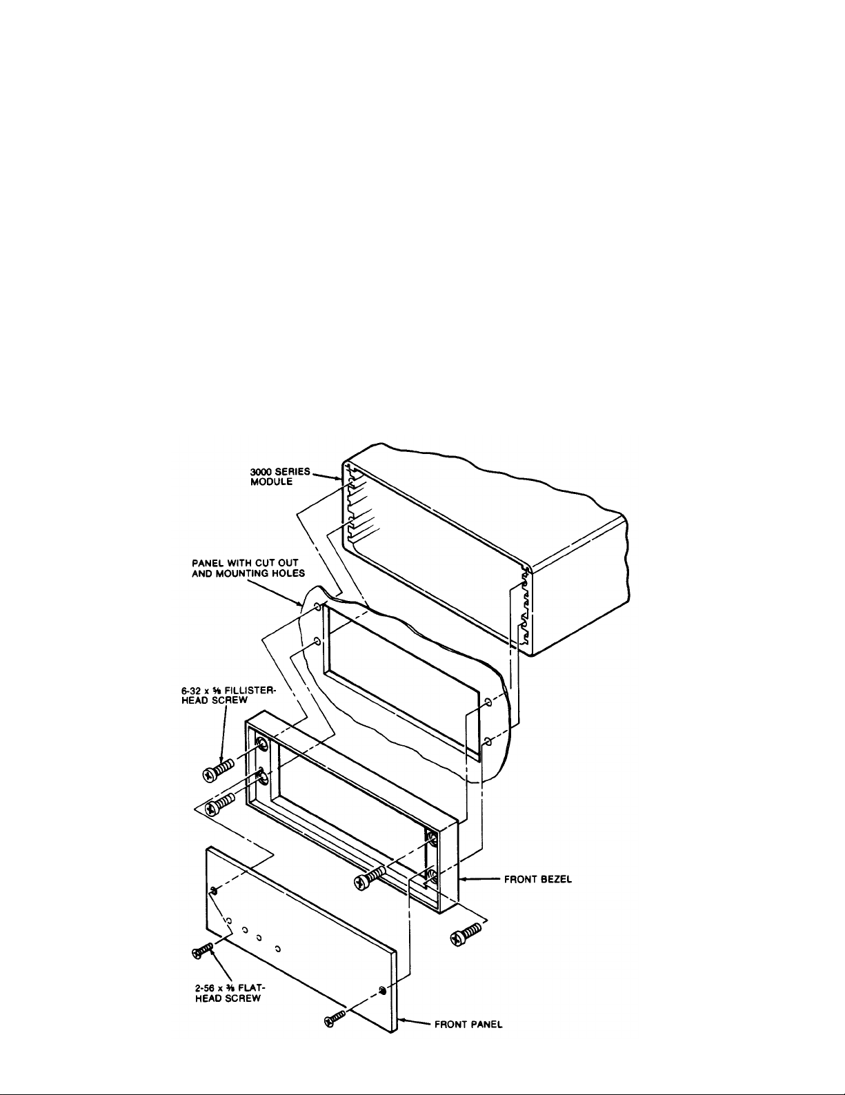
b. Remove the front bezel (four fillister-head screws fasten it to the
metal housing--see Fig. 2).
c. Make the panel cutout and drill the screw clearance holes shown in
Figs. 1C and 2. The front bezel can be used as a template to define
the rectangular cutout and to locate the clearance holes.
d. Hold the instrument behind the panel and use the four mounting screws
to reattach the front bezel to the metal housing, from the front of the
panel.
e.
Reinstall the front panel.
f. Tighten--BUT DON'T OVERTIGHTEN--the two securing screws of the rear-
panel I/O Connector. This will push forward the printed-circuit board
and all front-panel buttons and controls by about 1/8"--which is conse-
quently the maximum panel thickness allowed.
Fig. 2 Instrument
Panel Mounting
3
4
3.
AC POWER CONNECTION: Connect the supplied power cable to a 105-135 V-AC,
50-400 Hz source (for "F" versions, 210-260 V-AC; for "B" versions, there
is no external power connection). This is a three-conductor cord, plug-
ing into the AC power connector at the rear of the unit; the offset pin
connects to earth ground. To maintain the safety ground when operating
from a two-contact outlet, use a 3-prong-to-2-prong adapter and connect
the green pigtail on the adapter to earth ground.
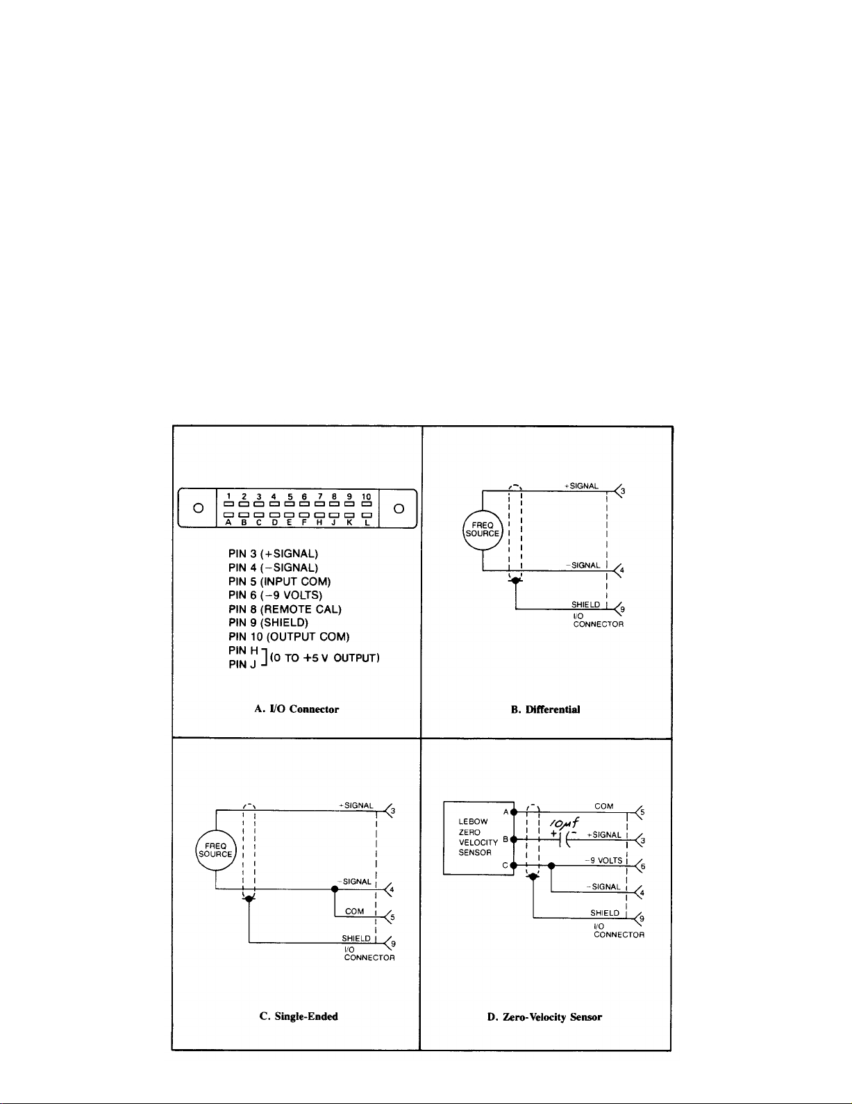
TRANSDUCER CABLING: The transducer is connected via the 3140A's rear-
panel I/O Connector. For pinout, see Fig. 3A, below. The frequency input
can be single-ended or differential, as shown in Fig. 3C and 3B, respecti-
vely. Shielded, twisted-pair cable is recommended. Fig. 3D gives the re-
quired cabling when the 3140A is used with Lebow Zero Velocity Sensors.
Fig. 3 I/O Wiring Data
2.

4.
5.
RANGE SELECTION: To access the internal bank of ten numbered range-
selection switches, remove the 3140A's front panel (two screws near each
edge--see Fig. 2). To select the desired full-scale frequency range,
place in the ON (i.e., downward) position the switches indicated in Table
2, below.
Table 2. Frequency Range Selection
REMOTE CALIBRATION CHECK: The 3140A can be placed in the REMOTE CAL mode
by connecting Pin 5 of the I/O Connector (Signal Common) to Pin 8. This
provides a means of periodically monitoring the instrument from a remote
location without pressing the front-panel CAL button. When the Remote Cal
input (Pin 8) is brought to a 0-volt (ground) level through the action of
an external switch, transistor driver, etc. (see Fig. 4), the effect is the
same as when the CAL button is pushed (see Section III, below).
Fig. 4 Remote Calibration
Connections
5

III. Calibration
1. Turn power ON by placing the rear-panel slide switch in the upward posi-
tion. With application of AC power, the front-panel red LED indicator
should light.
2. ZERO ADJUSTMENT: Establish a zero input to the 3140A by bringing the
transducer frequency to zero or by disconnecting the transducer from the
3140A I/O Connector. Then adjust the front-panel ZERO control (see Fig.
5, above) to produce an output of zero.
3. SPAN ADJUSTMENT: Press the front-panel CAL button. The input signal is
now replaced by a digitally divided, crystal-controlled frequency equal
to 80% of the full-scale value of the input ranqe selected in Step 4,
Section II, above. Now adjust the Coarse and Fine SPAN controls to
produce an output equal to 80% of the selected range. The 3140A is
4. TRIGGER LEVEL ADJUSTMENT: Turn the front-panel INPUT SENSITIVITY control
fully counterclockwise. Then, using the transducer as a frequency source,
apply the lowest-valued input signal for which a valid reading is requir-
ed. Then turn the INPUT SENSITIVITY control clockwise until a stable
output is observed.
FOR MODELS 3240A AND 3340A ONLY:
1A. POWER-UP and ZERO ADJUSTMENT: as in Steps 1 and 2, above.
2A. SCALE SELECTION: Determine the full-scale output of the transducer in
terms of the desired unit of measurement. For example, the full-scale
output for a flowmeter might be 5000 Hz, which corresponds (in units of
flow) to a measurement of, say, 728.2 cfm. Then select the full-scale
frequency ranqe, as explained in Step 4 of Section II. In our example,
this would be the 5000-Hz setting.
Now select the Digital Indicator scale that accommodates the full-scale
output of the transducer in the desired unit of measurement. In our ex-
ample, this scale would be ± 10000, with decimal point to the left of the
last zero, giving a full-scale reading of 1000.0, to accommodate a full-
scale measurement of 728.2 cfm. For the setting of scale and decimal-
point location, refer to the Model 3200/3300 Instruction Manual.
Fig. 5
Model
3140A
Front Panel
6
normally scaled for a full-scale output of +5 volts.

7
3A. SPAN ADJUSTMENT: Apply an input signal with a frequency equal to the
rated full-scale output of the transducer. Then adjust the Coarse and
Fine SPAN controls to produce a readout on the indicator of the value de-
termined in Step 2A, above--that is, of the full-scale transducer output
in terms of the desired unit of measurement (e.g., 728.2 cfm).
4A. TRIGGER LEVEL ADJUSTMENT: as in Step 4, above.
IV. Verification of Normal Operation
If the Model 3140A is suspected of faulty operation, you should do the fol-
lowing:
1.
2.
3.
If the unit is TOTALLY INOPERATIONAL (front-panel LED indicator does not
light), first check the primary power fuse (F1) located on the standup
board which forms the power-cord connection point. If this fuse is blown,
replace it with a 0.50-amp fuse ("F" version, 0.125-amp but not before
determining the cause of overload (inspect the input power connections for
any short-circuiting, etc.).
Push the front-panel CAL button, and observe the analog output. If it is
stable, noise-free, and adjustable via the Coarse and Fine SPAN controls,
then you can assume that all circuits--with the exception of the front-end
amplifier and trigger circuits--are functioning normally.
To check the front-end circuitry, replace the transducer and cable with a
transducer and cable known to be in good condition and operating reliably.
If the 3140A works properly with this different input source, then the
problem most likely lies in the original transducer/cable. However, if
the observed malfunction persists after this substitution, repairs to the
3140A are probably indicated.

MODEL
3200 / 3300
DIGITAL INDICATOR
SB.5
INSTRUCTION MANUAL
3000
Instrument Series

MODEL
3200 / 3300
DIGITAL INDICATOR
INSTRUCTION MANUAL
Model 3200/3300 Instruction Manual, v. SB.5
Pub. No. 3200/3300M.5, Issued 10/96
Part No. 91130
Daytronic Corporation
Dayton, OH • Tel (800) 668-4745
www.daytronic.com

Daytronic Corporation
TABLE OF CONTENTS
Section Page
1
Description ..................................................... 1
2
Installation ......................................................
4
3
Operation
....................................................... 7
4
Block Diagram Description .......................................
8
5
Verification of Normal Operation ..................................
15
LIST OF ILLUSTRATIONS
Figure
Page
1
3000 Series Instrument with Digital Indicator .......................
1
2
Full-Scale Displays for Three Ranges ..............................
6
3
Scale, Decimal Point, Dummy Zero Switches .......................
7
4
A/D Converter Timing Diagram ...................................
5Block Diagram Description
LIST OF TABLES
Table
Page
1
3000 Series Model Numbering ....................................
2
2
Specifications
.................................................... 4
PLEASE NOTE: Sections 6 and 7, Figures 6 and 7, and Table 3 have been
removed from this manual.
If you need information regarding specific 3200/3300 components and
circuitry, please contact the Daytronic Service Department at (937) 293-2566.
....................................... 13
10
Daytronic Corporation
INSTRUCTION MANUAL
3200/3300
SERIES DIGITAL INDICATOR
1. DESCRIPTION
The 3000
Instrument
Series
is a family of premium signal conditioning instru-
ments that includes models to
accomodate
virtually all types of transducers and
signal sources commonly encountered in electro-mechanical testing and control
operations. The 3000
Instruments
are available in three forms: Form 1 contains the
Signal Conditioner only; Form 2 is the Signal Conditioner with Digital Indicator;
Form 3 is the Signal Conditioner with Digital Indicator and Hi-Lo Limits. The
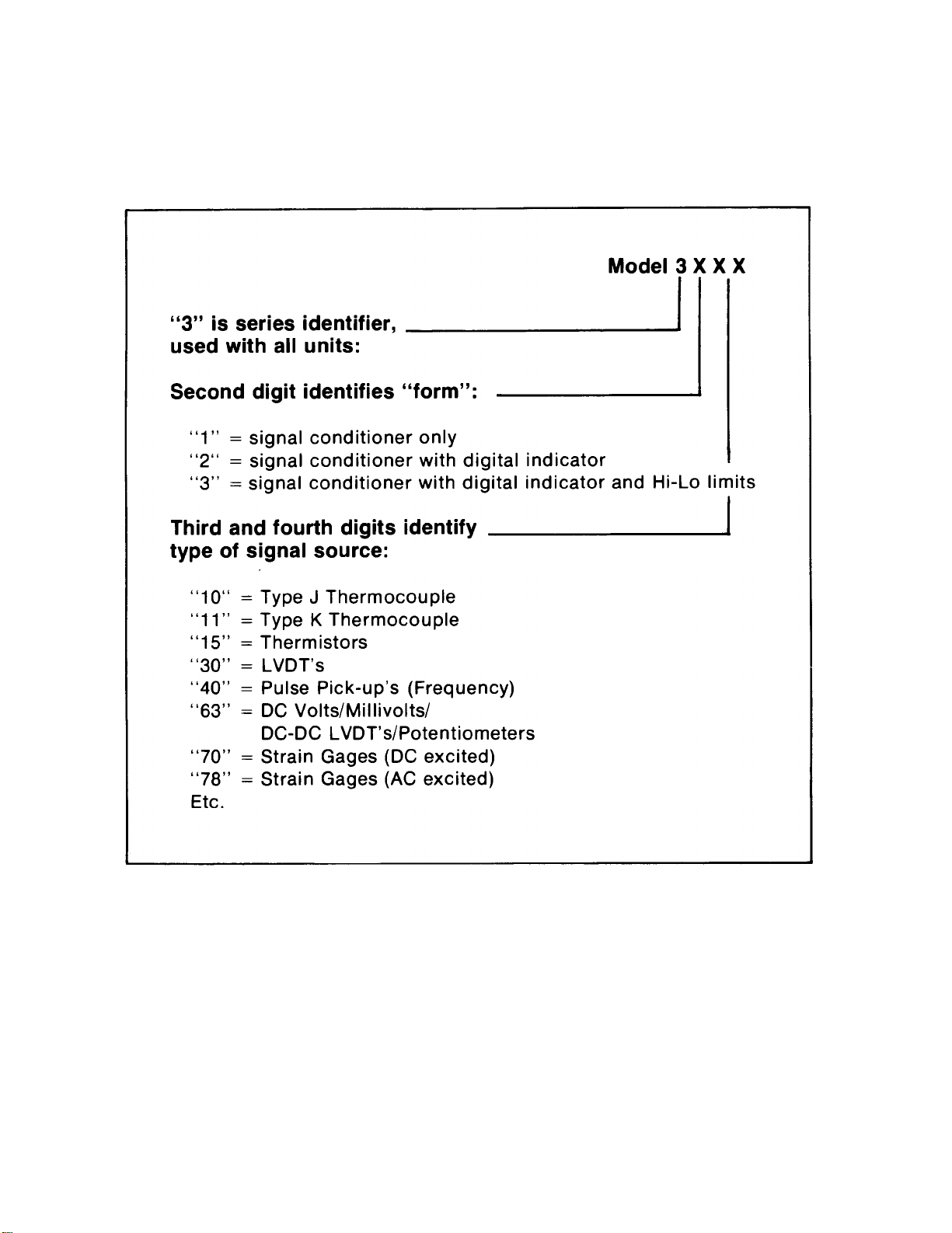
Model numbering system used with the 3000 Series identifies the form and the type
of signal source. This numbering system is further explained in Table 1. From Table
1, it can be seen that all models having a Digital Indicator are identified by a 32XX or
33XX number, with the last two digits identifying the type of signal source (ther-
mocouple, LVDT, etc).
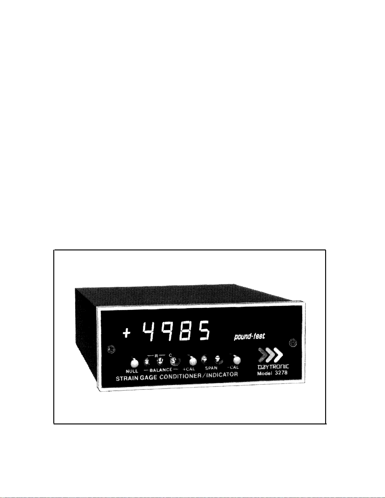
Figure 1. 3000 Series Instrument with Digital Indicator 1
"3000"
Digital Indicator
Table 1. 3000 Series Model Numbering
The 3000 Series instruction manual system is designed to provide the user with
the following documentation: (1) a separate instruction manual for each type of
Signal Conditioner purchased; (2) an instruction manual covering only the Digital
Indicator section of a 3000 Series instrument, but applicable to any Form 2 or Form
3 instruments; and (3) an instruction manual covering only the Hi-Lo Limit section
2

Daytronic Corporation
of a
3000
Series instrument, but applicable to any Form 3 instrument. It is the
purpose of this manual to cover the Digital Indicator section of all Form 2 and Form
3 instruments.
The Digital Indicator section of any Form 2 or Form 3 instrument consists of a
printed-circuit board on which are mounted the required circuit components for
digitizing the analog output of the Signal Conditioner and the light-emitting-diode
(LED) display. This board is mounted above the circuit board which contains the
components for the Signal Conditioner. The digits which comprise the display are
mounted on a small board which is affixed to the digitizer board with a right-angle
printed-circuit board header. The Form 3 instruments contain an additional
printed-circuit board for the Hi-Lo Limit circuitry.
The LED display is comprised of six orange digits with polarity sign. The 0.4 inch
height of the digits, combined with the inherent brilliance of an LED type of display,
make the display easily discernible in normal room lighting. The display is viewed
through the red plastic front panel of the instrument to provide filtering of external
light and enhance the display brilliance. The front panel is opaque except for that
portion through which the display is viewed. A typical 3000 Instrument with Digital
Indicator is shown in Figure 1.
The Digital Indicator scaling is selected with rear-panel pushbutton switches.
Full-scale values of ±5000 counted by
1's,
±
10000 counted by
2's,
or
±20000
counted by
5's
can be selected. The most significant digit (MSD) of the display
contains the polarity sign and is either unlit or lights as a 1for displays of 10000 or
greater. The least significant digit (LSD) is a dummy zero which can be turned ON
or left unlit as desired. In addition, decimal-point position can be selected to give
display readings as follows:
1.XXXX,
lX.XXX,
1XX.XX,
1XXX.X,
or
1XXXX
(no decimal point). Decimal-point location and dummy zero selection are also
accomplished with rear-panel switches (miniature slide-switch bank). When the
20000 scale is selected, the display is digitally limited to read a maximum number of
19995 since the MSD is either unlit or reads a "1" for displays of 10000 or greater.
The 5000 and 10000 scales are analog limited to an overrange of approximately 5600
and 11200, respectively. An overrange condition on any range is indicated by a
flashing display. The sampling rate of the display is 3 samples per second. The
Digital Indicator specifications are summarized in Table 2.
3

"3000" Digital Indicator
Table 2. Specifications
Display: Orange LED’s, six digits with polarity sign, 0.4 inch height.
MDS
is either unlit or reads a 1 and contains the polarity sign. LSD is a
dummy zero which can be programmed to be lit or unlit (rear-panel
switch).
Scaling: Selectable at rear panel; full-scale values of ±5000 counted
by
1's,
±
10000 counted by
2's,
or
±20000
counted by
5's.
Decimal Point: Decimal-point location can be selected with rear-
panel switches as follows:
1.XXXX,
1X.XXX,
1XX.XX,
1XXX.X,
or
1XXXX
(no decimal point).
Sampling Rate: 3 samples per second.
Legends: Each instrument supplied with an appropriate assortment
of user-installable rub-on engineering unit legends.
2. INSTALLATION
The 3000 Series Instruments can be operated as bench-top instruments or they
can be rack- or panel-mounted. Dimensions for all three types of mounting and
corresponding mounting instructions are given in the accompanying Signal Con-
ditioner Instruction
Manual.
The following paragraphs provide the instructions for
legend installation, scale selection, decimal point/dummy zero selection, and ac
power connection.
Legend
Installation.
A sheet of dry-transfer lettering is supplied with each
instrument to provide the user with a means of affixing an engineering-unit legend to
the front panel. The sheet contains the common engineering units encountered in
making electro-mechanical measurements and additional alpha-numeric charac-
ters. Space is supplied on the front panel to affix the desired legend to the right of the
display. To affix the legend to the front panel, press the dry-transfer sheet firmly
4

Daytronic Corporation
against the panel with the desired legend or character situated in place. Rubbing the
legend or character with a ball-point pen will cause the legend to be transferred onto
the panel. The legend can be protected from scratches which may occur during
calibration/operation of the instrument by lightly spraying it with Krylon
#1306
Workable Fixative.
If it is desired to change a legend, remove the legend to be replaced by pressing
masking tape against the legend, then pulling off the gummed tape.
Scale Selection. Figure 2 shows the full-scale display for the three selectable
scales: ±5000 counted by 1's,±10000 counted by 2's, and ±20000 counted by 5's.
The figure also indicates the last active digit and the dummy zero which can be lit for
any scale selection. The first digit of the display contains the polarity sign and lights
as 1on the 10000 and 20000 scales for values equal to or greater than 10000. On the
20000 range, because the most significant digit is either unlit or a 1and the count is
by 5's,
the greatest number which can be displayed is 19995. Of course, this would be
displayed as 199950 if the dummy zero were lit.
Scale selection is accomplished with the two pushbutton switches located at the
rear panel. The panel is marked to indicate which switches are pushed IN or left
OUT for the corresponding scale selection. The switches have a push-push action
and are illustrated, with the scale selection coding, in Figure 3. With both switches
OUT, the ±5000 range is selected. With the left switch OUT and the right switch
IN, the
±
10000 range is selected. With the left switch IN and the right switch OUT,
the
±
20000 range is selected.
Decimal Point/Dummy Zero Selection. Decimal-point location and
dummy-
zero activation are selected with a rear-panel miniature slide switch bank. The
switch bank is marked on the rear panel as shown in Figure 3. The decimal-point
position can be fixed at any one of the display locations indicated on Figure 3. Place
any one of slide switches 1through 4 ON to light the decimal point at the desired
location. Place slide switch 5 ON if no decimal point is to be lit. To activate the
dummy zero (digit to the right of last active digit will continuously light as a zero),
place slide switch 6 ON.
AC Power Connection. To protect operating personnel, the 3000
Series
Instru-
ments are equipped with a three-conductor power cord. When the cord is plugged
into the appropriate receptacle, the instrument is grounded. The offset pin on the
5

"3000" Digital Indicator
Figure 2. Full-Scale Displays for Three Ranges
6
A. ±20000 Range
B. ±10000 Range
C. ±5000 Range

Daytronic Corporation
power cord is ground. To maintain the safety ground when operating the instrument
from a two-contact outlet, use a three-prong to two-prong adaptor and connect the
green pigtail on the adaptor to ground.
To prepare the instrument for operation, connect the power cable to a 105-135
volt ac, 50-400 Hz power source. The instrument can use up to 5watts of power.
3. OPERATION
The only operation required is turning ON/OFF ac power to the instrument. This
is accomplished with the rear-panel slide switch (see Figure 3). The display lights
immediately when ac power is ON.
NOTE
In all instances, a flashing display indicates that an overrange condition
has occurred, and it is likely that the Signal Conditioner amplifiers are
being overdriven. The 5000 and 10000 ranges are analog limited at
approximately 5600 and 11200, and while a number may be displayed, if
Figure 3.
Scale,
Decimal Point, Dummy Zero Switches 7
Other manuals for 3000 series
2
This manual suits for next models
3
Popular Industrial Electrical manuals by other brands

Murata
Murata GRM1555C2A7R4CA01 Series Reference sheet

Murata
Murata GRM0335C2A3R6WA01 Series Reference sheet

S&C
S&C IntelliRupter PulseCloser instruction sheet

Murata
Murata GRM2165C1H751JA01 Series Reference sheet

Murata
Murata GRM0335C1H8R8DA01 Series Reference sheet

Murata
Murata GRM1555C1ER70BA01 Series Reference sheet

Rockwell Automation
Rockwell Automation Allen-Bradley CENTERLINE 1500 user manual

Murata
Murata GRM31CR61E475KA88 Series Reference sheet

ABB
ABB SACE Emax 2 manual

Circutor
Circutor OPTIM P&P Series instruction manual

Graphic Whizard
Graphic Whizard Finishmaster 100 Reference manual

Kathrein
Kathrein 20110019 Mounting instructions


