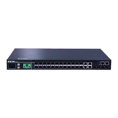
DCN DCRS-9800 Series Manual

DCRS-9800 InstallManual Content
1
Content
CHAPTER 1 PRODUCT OVERVIEW.........................................1-1
1.1 PRODUCT BRIEF .................................................................................1-1
1.1.1 Introduction...........................................................................................1-3
1.1.2 Main Features........................................................................................1-3
1.2 TECHNICAL SPECIFICATIONS.................................................................1-4
1.3 PHYSICAL SPECIFICATIONS ..................................................................1-5
1.4 HARDWARE COMPONENTS...................................................................1-5
1.4.1 Chassis..................................................................................................1-5
1.4.2 Introduction to DCRS-9800 Series Cards .........................................1-15
1.4.3 Interface description...........................................................................1-26
1.4.4 Power supply ......................................................................................1-27
1.4.5 System Backplane..............................................................................1-29
1.4.6 Fan Tray...............................................................................................1-29
1.4.7 Dust Gauze..........................................................................................1-31
1.4.8 Rear Panel ...........................................................................................1-32
1.4.9 Side Panels..........................................................................................1-34
1.5 SYSTEM FEATURES ...........................................................................1-37
1.5.1 DCRS-9808 System Features.............................................................1-37
1.5.2 DCRS-9816 System Features.............................................................1-37
CHAPTER 2 HARDWARE INSTALLATION...............................2-1
2.1 BASIC REQUIREMENTS ........................................................................2-1
2.1.1 Site Requirements ................................................................................2-1
2.1.2 Temperature and Humidity Requirements..........................................2-1
2.1.3 Dust and Particles.................................................................................2-2
2.1.4 Preventing Electrostatic Discharge Damage......................................2-3
2.1.5 Anti-interference Requirements...........................................................2-3
2.1.6 Rack Configuration...............................................................................2-3
2.1.7 Power Supply Requirements ...............................................................2-4
2.2 SAFETY GUIDELINES ...........................................................................2-5
2.3 SAFETY WARNING ...............................................................................2-5
2.4 HOT LINE WORK SAFETY GUIDELINES ..................................................2-5
2.5 PREPARING FOR INSTALLATION.............................................................2-6
2.5.1 Checking Switch Hardware Configuration and Accessories ............2-6
2.5.2 Required Tools and Utilities.................................................................2-7
2.6 HARDWARE INSTALLATION ...................................................................2-8
2.6.1 Switch Installation ................................................................................2-8
2.6.2 Switch grounding................................................................................2-12
2.6.3 Card and module installation.............................................................2-13
2.6.4 Connecting to the Console ................................................................2-21
2.6.5 Connecting to the Management Port ................................................2-21

DCRS-9800 InstallManual Content
2
2.6.6 SFP transceiver installation...............................................................2-21
2.6.7 Copper Cable/Fiber Cable Connection .............................................2-22
2.6.8 Power supply connection ..................................................................2-23

DCRS-9800 InstallManual Chapter 1 Product Overview
1-1
Chapter 1 Product Overview
RECOMMENDATION: Please read this manual first before using the switch,
following the instructions to avoid damaging the device.
1.1 Product Brief
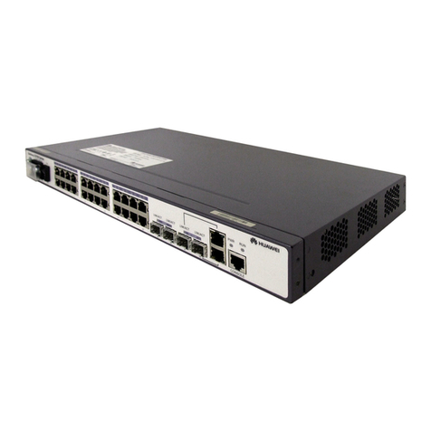
Fig 1-1 DCRS-9808 Switch

DCRS-9800 InstallManual Chapter 1 Product Overview
1-2
Fig 1-2 DCRS-9816 Switch

DCRS-9800 InstallManual Chapter 1 Product Overview
1-3
1.1.1 Introduction
DCRS-9800 Series Routing Switches are advanced next-generation switches
developed independently by Digital China, which promise users a free and smooth
journey in the Internet with their unparalleled backplane bandwidth. DCRS-9800 Series
Routing Switches can fully satisfy users’ demands on a both comprehensive and
convenient networking model as well as the upgrading of next-generation networks due to
their spectacular characteristics, including complete IPV6 features, intelligent and secure
power management, considering design of noise reduction and energy saving, highly
efficient network management, next-generation 100G internet interfaces, and outstanding
stability at the level of service provider.
DCRS-9800 Series Routing Switches can serve as core devices in enterprise
networks and carrier-level as well as convergence devices in city-wide networks, offering
flexible networking models: DCRS-9808 provides 8 slots for short card or 4 slots for full
cards; DCRS-9816 provides 16 slots for short card or 8 slots for full card, supporting
mixing of short and full cards. Two separate power systems are used to realize the POE
function of boardcards in this series, And most components of DCRS-9800 Series Routing
Switches interchangeable, including main control management modules, service
boardcard modules, power modules, and etc, which guarantees a convenient networking
for users. This series of switches also boast high stability owing to the management
module, redundant backup and load-balancing technology, and intelligent power
management.
1.1.2 Main Features
DCRS-9808 provides 2 management module slots, 4 slots for full cards or 8 slots for
short cards. Users can easily switch among 4-full-card mode, 8-short-card-mode and
the mode of 4 short cards and 2 full cards by moving a horizontal beam. All three
modes support single/dual main control mode.
DCRS-9808 supports 2+1 system power backup and 2+1 POE power backup.
DCRS-9816 provides 2 management module slots, 8 slots for full cards or 16 slots for
short cards. Users can easily switch among 8-full-card mode, 16-short-card-mode and
the mode of 8 short cards and 4 full cards by moving a horizontal beam. All three
modes support single/dual main control mode.
DCRS-9816 supports 3+1 system power backup and 3+1 POE power backup.
Store-and-forward switching, ensuring minimal latency.
Auto MDI/MDI-X, enabled on all RJ-45 ports, allows connections to other switches
using a non-crossover twisted pair cable.

DCRS-9800 InstallManual Chapter 1 Product Overview
1-4
Full-duplex IEEE802.3x flow control, half-duplex backpressure flow control.
Console management port provided.
Port working status and statistics available.
Restart and reset to factory setting can be done both locally and remotely.
TFTP /FTP firmware upgrade available.
Can be installed into standard 19-inch chassis.
1.2 Technical specifications
Protocols and Standards
□ IEEE802.3 10BASE-T Ethernet
□ IEEE802.3u 100BASE-TX/FX Fast Ethernet
□ IEEE802.3x Flow control
□ IEEE802.1x access control
□ IEEE802.1D/w Spanning Tree
□ IEEE802.1p Class of Service
□ IEEE802.1Q VLAN
□ IEEE802.3ad Link Aggregation
□ TFTP/FTP
□ DHCP
□ BootP
□ Telnet
□ IP/UDP/TCP/ICMP
□ HTTP
□ SNMP V1/V2C
□ RIP
□ OSPF
□ BGP
Management Protocols and Methods
□ CLI command line
□ SNMP V1/V2C enabled, available through Network management systems such as
ECview
□ Telnet management enabled
□ RFC1757 RMON(1, 2, 3, 9)
MIB Library
□ RFC1213 MIB II
□ RFC1493 Bridge MIB

DCRS-9800 InstallManual Chapter 1 Product Overview
1-5
□ RFC1643 Ether-Like MIB
□ Digital China Private MIB
1.3 Physical Specifications
Management Port
□ One RJ-45 serial port for each management module
AC Power Input
□ 200 ~ 264VAC, 50 ~ 60Hz
□ Built-in Universal Power Supply
Power Consumption
□ DCRS-9808: 1200W Max
□ DCRS-9816: 1800W Max
Operating Temperature
□ 0°C ~ 45°C
Storage Temperature
□ -40°C ~ 70°C
Relative humidity
□ 10% ~ 90% with no condensate
Dimension
□ DCRS-9808 436mm×708mm×450mm (W x H x D)
□ DCRS-9816 436mm×842mm×450mm (W x H x D)
Weight
□ DCRS-9808: 65kg (max. full configuration weight)
□ DCRS-9816: 80kg (max. full configuration weight)
Mean Time Before Failure
□ Min. 80,000 Hours MTBF
1.4 Hardware Components
DCRS-9800 consists of the chassis, power supply system, ventilation system, system
board, etc.
1.4.1 Chassis
1.4.1.1 DCRS-9808 Chassis

DCRS-9800 InstallManual Chapter 1 Product Overview
1-6
The DCRS-9808 uses a 19-inch Rack Mountable Chassis, with the standard
dimensions of 436mm(W) x 708mm(H) x 450mm(D). The frame includes a fan area, a
module area, a power area and an air-inlet area. The fan area has a fan disc (with four
48v DC axial-flow fan imbedded in it), can be plugged in and out from back of the box,
supporting hot-plug. The module area is the core part of the DCRS-9808 switch frame,
including two main control slots and 8 line card slots. Users can change the 8 slots for
short cards into 4 slots for full card by removing the horizontal beams in slots for short
cards. The power area locates on the right side of the frame, including two separate power
systems both adopting 2+1 redundant power mode. The upper part of the power area is
the system power module, providing power for the whole system in the box, while the
lower part is POE power module, providing POE power for the POE board in the system.
At the bottom of the frame, there is a dust screen to filter the air entering the board slot
frame. There are also an ESD jack and a grounding stud.
Besides, two handles are places at the bottom on each side of the frame for carrying
it.

DCRS-9800 InstallManual Chapter 1 Product Overview
1-7
Fig 1-3 DCRS-9808 Module Outlook

DCRS-9800 InstallManual Chapter 1 Product Overview
1-8
Fig 1-4 DCRS-9808 Front Panel View

DCRS-9800 InstallManual Chapter 1 Product Overview
1-9
①Management slot: It supports two management slots. MRS-9800-MI
etc.can be inserted in to the Management slots.
②Network slot: It provides 4 slots for full cards or 8 slots for short
cards.Various full and short network modules can be added to the
network slots.such as full card MRS-9800-8XFP, short card
MRS-9800-24GT and MRS-9800-24GB and more.
③Power slot: supporting system power module and Poe power module,
both independent modules with 2+1 redundant backup mode. It
supports 600W AC or 600W/1000W DC modules.
④Fan tray slot: Supports up to one system fan assemblies, each
assembly consists of four axial fans. Fan tray slot supports intellectual
management.
⑤Dust gauze slot: Exterior air inlet for the ventilation subsystem.
1.4.1.1.1 Board Rack
The board rack consists of board slots, short card brace and a system board.
DCRS-9808 has 8 slots for short cards in two vertical layers. Users can combine two
slots for short cards into a slot for full card by moving the horizontal beam. In the middle
are two slots for full cards, labeled as M1 and M2. When there is only on main control
module in M1 or M2, the switch works in single main control mode. When two main control
modules are slotted in, the working mode becomes dual main control mode.
A board power indicator (printed on the panel as PWR) and board running status
indicator (printed on the panel as RUN) are provided for each board. On the Main Control
cards there are a Master-Slave indicator (printed on the panel as M/S) and a fan assembly
status indicator (printed on the panel as Fan). There is also a interface status indicators
for corresponding management interfaces and network interfaces (printed on the panel as
Link and Act).
The DCRS-9808 system board is an essential part of the switch, located inside the
switch and providing interconnectivity between the management switch modules (short for
management card) and network interface modules (line card), and for all management
and control signals.
1.4.1.1.2 Power Supply
The power modules of DCRS-9808 switches and DCRS-9816 switches are
exchangeable, with an AC input from the front and a 48V DC output at back. When
powering in AC mode, the input voltage should be 110V/220V AC. The permissible range
of input power supply is 90~264VAC,50~60Hz. The maximum output power of single
power supply module is 600W and 1000W. Powers of 600W and 1000W should not be
mixed.

DCRS-9800 InstallManual Chapter 1 Product Overview
1-10
When using DC power supply, we should adopt power supply of -48V DC. The
permissible range of power supply is -36V~-72VDC. The maximum output power of
single power supply module is 600W and 1000W. Powers of 600W and 1000W should not
be mixed.
1.4.1.1.3 Ventilation and Cooling System
The operating ambient temperature of the DCRS-9808 is 0 ~ 45°C, the thermal
design of the equipment can ensure that the surface temperature of the device will not
exceed the 50 to 80 percent of the highest temperature allowable.
The switch uses fan assemblies to disperse heat, with a bottom-up ventilation along
an air way. to facilitate air circulation, so that the switch can maintain normal operation
under specified environmental conditions. The fan tray is attached to the fan tray slots
back the board rack, and ventilation is provided via 4 axial fans that pump out air. The fans
are three-speed ones supporting intellectual management. The main control module can
automatically adjust the fan speed according to the internal temperature of the system,
that is, the temperature inside the system can be changed by adjusting the air speed.
When the system is powered on, fans are working at middle speed by default. If the
temperature exceeds a secure threshold, the main control module will set the fan at high
speed. Such intellectual control of fans not only reduces noise but also saves energy,
which means a green and environmental-protective system. Fan trays are hot swappable
for maintenance, their status are indicated by the FAN indicators on the main switch panel.
In addition, dust gauze is provided on the bottom of the board rack for filtering the air
circulating through the rack. The dust gauze can be unplugged and removed through the
front for maintenance.
1.4.1.2 DCRS-9816 Chassis
The DCRS-9816 uses a 19-inch Rack Mountable Chassis, with the standard
dimensions of 436mm(W) x 842mm(H) x 450mm(D). The chassis consists of functional
block, thermal block, and power supply block.
The function module block is a board rack, which is the supporting structure for
DCRS-9816 system boards (10 boards max). Users can configure 18 boards with short
card brackets. The two slots in the middle are for main control modules, labeled as M1
and M2. On their right and left sides, there are both two vertical layers of slots for short
cards, with a total of 18. A slot for short card together with the one right below it can be
combined into a slot for full card.
The thermal block is located on the upper part of the board rack, allowing one fan
trays (6 axial fans for fan tray). Dust gauze is provided under the board rack for filtering air
circulation through the rack.

DCRS-9800 InstallManual Chapter 1 Product Overview
1-11
The power block is under the dust gauze. There are two independent power systems:
system power and POE power system, separately used for system power and POE
power, allowing at most four power modules. The power modules insert into the power
slots from the front. A grounding post has been provided on back of the rack for grounding
connections.
In addition, on both sides of the lower section of the chassis, a handler is provided for
easier transport.

DCRS-9800 InstallManual Chapter 1 Product Overview
1-12
Fig 1-5 DCRS-9816 Module Outlook

DCRS-9800 InstallManual Chapter 1 Product Overview
1-13
Fig 1-6 DCRS-9816 Front Panel view

DCRS-9800 InstallManual Chapter 1 Product Overview
1-14
①Management slot: 2 management slots are provided. One or two
management switching modules MRS-9800-MI can be inserted in to the
Management slots.
②Network slot: 8 full-card or 16 short-card network slots are provided.
Various network modules can be added to the network slots.
③Power slot: used for system power and POE power supply modules. It
supports up to four 600W AC or 1000W AC modules or four 600W DC
or 1000W DC modules. Powers of 600W and 1000W should not be
used in system power or POE power at the same time.
④Fan tray slot: Only one intellectual fan management module is allowed,
controlling six 48V DC highly efficient axial-flow fans in the fan disc.
⑤Dust gauze slot: exterior air inlet for the ventilation subsystem.
1.4.1.2.1 Board Rack
The board rack consists of board slots and a system board.
The boards are inserted vertically into the DCRS-9816 20 unit boards are provided.
These include 4 management slots in the middle for management switch modules, the
underside slots marked specially in red as M1 and M2, the upside slots marked specially
in red M3 and M4. The other 16 board slots are network slots for various network interface
modules, the underside slots sequenced as 1 to 8 from left to right, the upside slots
sequenced as 9 to 16 from left to right. The box of a DCRS-9816 switch supports the
full-card mode, the short-card mode and the mixed mode.
The DCRS-9816 system board is an essential part of the switch, located inside the
switch and providing interconnectivity between the management switch modules (short for
management card) and network interface modules (line card), and for all management
and control signals.
1.4.1.2.2 Power Supply
The power slot frame of DCRS-9816 locates at the bottom of the box, including 8
slots arranged in two lines. The upper four slots are the power slot frame for system
power, while the lower four are the power slot frame for POE power. These two powers
are separate. Two kinds of AC powers are available: 600W AV modules and 1000W AV
modules. Different AC powers are forbidden to be used in one power slot frame, but can
be slotted into different ones.
The power system receives input from the front, saving the trouble of choosing
distributing boxes. When using AC power, the input voltage should be 110V/220V AC.
Power fluctuations between the ranges of 90~256VAC and 50~60 HZ are allowed. When
using DC power, the input voltage should be -48V. Power fluctuations between the range
of -36V~-72V are allowed. It is forbidden to mix the two kinds of powers simultaneously.

DCRS-9800 InstallManual Chapter 1 Product Overview
1-15
1.4.1.2.3 Ventilation and Cooling System
The operating ambient temperature of the DCRS-9816 is 0 ~ 45°C, the thermal
design of the equipment can ensure that the surface temperature of the device will not
exceed the 50 to 80 percent of the highest temperature allowable.
The switch uses fan assemblies to disperse heat, with the air flow being drawn in
through the bottom section and out through the upper section to facilitate air circulation, so
that the switch can maintain normal operation under specified environmental conditions.
One fan tray is attached to the fan tray slot from the back of board rack, and ventilation is
provided via 6 axial fans that pump out air. Fan trays are hot swappable for maintenance,
their status are indicated by the FAN indicators on the main switch panel. In addition, dust
gauze is provided under the board rack for filtering the air circulating through the rack. The
dust gauze can be unplugged and removed through the front for maintenance.
The fan disc supports the intellectual management of automatic adjustment of air
speed and air volume according to the monitored temperature inside the box to save
energy and reduce noise. There are three different fan speeds: high, middle, low. If the
temperature inside the box exceeds 50 degrees Celsius, the fans will start working at high
speed automatically to increase the air speed, hence rapidly decrease environment
temperature.
1.4.2 Introduction to DCRS-9800 Series Cards
The following three cards for the DCRS-9800 series are currently available:
zMain control card (MRS-9800-MI): The central switching and controlling module
for the DCRS-9808 and DCRS-9816. System status control, switch
management, user access control and administration, and network operation
maintenance are performed here.
zMain control card (MRS-9808-M): The central switching and controlling module
for the DCRS-9808. System status control, route management, user access
control and management, and network operation maintenance are performed
here.
z24 fiber GB ports line card (MRS-9800-24GB): implements 2-layer and 3-layer
wire-speed switching and routing function of 24 1000Mbps optical interfaces and
IPv6 wire-speed transmission.
z24 copper GT ports line card (MRS-9800-24GT): supporting 24 1000Base-T
copper ports for layer 2 and layer 3 switching and routing and IPv6 wire speed
forward.

DCRS-9800 InstallManual Chapter 1 Product Overview
1-16
z40G XFP fiber interface line card(MRS-9800-4XFP): implements 2-layer and
3-layer wire-speed switching and routing function of 4 10000Mbps optical
interfaces and IPv6 wire-speed transmission, supports MPLS function.
1.4.2.1 MRS-9800-MI
The MRS-9800-MI is switching module for the DCRS-9800 series switch. System
status control, switch management, user access control and management, and network
maintenances are performed here. The board can be inserted into M1 or M2 slots of the
chassis for Master-Slave redundancy.
1.4.2.1.1 Front Panel
The MRS-9800-MI comes with 1 CF card port, 1 Console port (control console), 1
10/100Base-Tx Ethernet port (management port) and a reset key.
The Front Panel view is shown below:
Fig 1-7 MRS-9800-MI Front Panel view
1.4.2.1.2 Front Panel - Indicator
The following table describes the front panel indicators of MRS-9800-MI:
Table 1-1 MRS-9800-MI indicators description
1) PWR:the power-on indicators of the board
Indication
Light
Meaning Status Description
On (Green) Card powered
PWR power
indicators Off Card powered off
2) Run:the run status indicators of the board
Indication
Light
Meaning Status Description
Green, blink Cards operating normallyRUN run status
On all along
or off
Cards operating abnormally
3) M/S:Master-Slave indicator

DCRS-9800 InstallManual Chapter 1 Product Overview
1-17
Indication
Light
Meaning Status Description
On (Green) MasterM/S Master-Sla
ve indicator Off slave
4) Alarm:the status-monitoring indicators of the board
Indication
Light
Meaning Status Description
Red, blink The temperature of the board is
abnormal or system power is too
low.
ALM Alarm
indicator
On (Green) The temperature and power of the
board are normal.
5) Power:8 indicators for power modules, the location of each being in accordance with
the power it relates to.
Indication
Light
Meaning Status Description
On (green) The power module is in position and
works normally.
On (red) The power module is in position but
works abnormally.
POWER
SYS
indicators
for the
system
power
status
Off The power module is absent.
On (green) The power module is in position and
works normally.
On (red) The power module is in position but
works abnormally.
POWER
POE
indicators
for the POE
power
status
Off The power module is absent.
6) FAN:Fan trays status
Indication
Light
Meaning Status Description
On (green) The fan tray is in position and works
normally.
Fan Fail Fan trays
status
indicator On (red) Fan tray malfunction.

DCRS-9800 InstallManual Chapter 1 Product Overview
1-18
On (green) The fan tray is in position.FAN OK Fan trays
position
indicator Off The fan tray is absent.
7) Line LED:indicators for line cards
Indication
Light
Meaning Status Description
On (green) The line card is inserted.
green, blink The line card is registered, and
software works normally.
On (red) Line card software works
abnormally.
red, blink The temperature of the line card is
abnormal, or the POE power is too
low.
LC
STATUS
line cards
indicator
Off The line card is absent.
8) CF STATUS:the indicator for the status of CF cards
Indication
Light
Meaning Status Description
On (green) The CF card is in position. Succeed
in linking the Ethernet management
port, no data transmission.
CF
STATUS
the
indicator
for the
status of
CF cards
Off Fail in linking the Ethernet
management port.
9) Eth:Indication lights for the status of Ethernet management ports.
Indication
Light
Meaning Status Description
green, blink Data are being transmitted.ACT Managing data
transmission
on the port
Off No data transmission.
On (green) Succeed in linking the Ethernet
managing port.
LINK Managing the
link of the port
Off Fail in linking the Ethernet
management port.
This manual suits for next models
2
Table of contents
Other DCN Switch manuals
Popular Switch manuals by other brands
Phoenix Contact
Phoenix Contact FL SWITCH EP74 Series Quick start manual
Siemens
Siemens RUGGEDCOM RSG920P installation guide
Digitus professional
Digitus professional DN-651108 user manual
EtherWAN
EtherWAN TG103H installation guide
MDT Technologies
MDT Technologies Glass Push Button II Smart Technical manual
VigilLink
VigilLink VLWP-DHC-TR user manual
