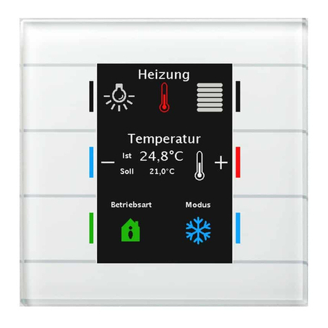
MDT Technologies Glass Push Button II Smart User manual

MDT technologies GmbH, Geschäftsbereich Gebäudeautomation
State 11/2020 - Version 1.1
Technical Manual
MDT Glass Push Button II Smart
MDT Push Button Smart 86
BE-GT20W.01 from R2.0 BE-TAS86.01
BE-GT20S.01 from R2.0 BE-TAS86T.01
BE-GT2TW.01 from R2.0
BE-GT2TS.01 from R2.0
Further Documents:
Datasheets:
https://www.mdt.de/EN_Downloads_Datasheets.html
Assembly and Operation Instructions:
https://www.mdt.de/EN_Downloads_Instructions.html

Technical Manual
Glass Push Button II Smart & Push Button Smart 86
MDT technologies GmbH, Geschäftsbereich Gebäudeautomation
Phone: +49-2263-880 • Fax: +49-2263-4588 • E-Mail: knx@mdt.de • www.mdt.de
2
2
1 Content
1 Content................................................................................................................................................. 2
2 Overview.............................................................................................................................................. 4
2.1 Overview devices.......................................................................................................................... 4
2.1.1 Special functions of the Glass Push Button II Smart & Push Button Smart 86 ..................... 4
2.2 Usage & Possible Applications.................................................................................................... 5
2.3 Exemplary Circuit Diagrams......................................................................................................... 6
2.4 Structure & Handling .................................................................................................................... 6
2.5 Settings at the ETS-Software ........................................................................................................ 7
2.6 Commissioning.............................................................................................................................. 7
2.7 Reload Symbols............................................................................................................................. 7
3 Communication Objects....................................................................................................................... 8
3.1 Default settings of the communication objects.............................................................................. 8
4 Reference ETS-Parameter.................................................................................................................. 14
4.1 Hardware Selection ..................................................................................................................... 14
4.2 Operation / Display ..................................................................................................................... 14
4.2.1 General Settings ................................................................................................................... 14
4.2.2 Display Settings.................................................................................................................... 16
4.2.2.1 Display Presentation...................................................................................................... 16
4.2.2.2 Adaption to ambience.................................................................................................... 17
4.2.2.3 User-defined colors ....................................................................................................... 20
4.2.2.4 Priority of HVAC Status ............................................................................................... 20
4.2.3 Information screen................................................................................................................ 22
4.2.3.1 Presentation in Standby................................................................................................. 22
4.2.3.2 Status values 1-3............................................................................................................ 25
4.2.3.3 Messages/Alarms........................................................................................................... 26
4.3 Push Button functions ................................................................................................................. 29
4.3.1 Display mode/Button activation/Level setting..................................................................... 29
4.3.2 Level setting ......................................................................................................................... 32
4.3.3 Overview: Two-button function / Single-button function.................................................... 33
4.3.4 Slap-/Cleaning function........................................................................................................ 34
4.4 Push button functions.................................................................................................................. 36
4.4.1 Identical parameter –Blocking object.................................................................................. 36
4.4.2 Identical parameter –Function name ................................................................................... 36
4.4.3 Identical parameter –Description of objects........................................................................ 37
4.4.4 Switch –General .................................................................................................................. 38
4.4.4.1 Switch with the two-button function............................................................................. 39

Technical Manual
Glass Push Button II Smart & Push Button Smart 86
MDT technologies GmbH, Geschäftsbereich Gebäudeautomation
Phone: +49-2263-880 • Fax: +49-2263-4588 • E-Mail: knx@mdt.de • www.mdt.de
3
3
4.4.4.2 Subfunction: Switch ...................................................................................................... 40
4.4.4.3 Subfunction: Toggle...................................................................................................... 40
4.4.4.4 Subfunction: Send status ............................................................................................... 41
4.4.4.5 Subfunction: Send status with on-delay ........................................................................ 42
4.4.4.6 Subfunction: Send status with off-delay........................................................................ 43
4.4.4.7 Presentation on display.................................................................................................. 44
4.4.5 Send values........................................................................................................................... 44
4.4.5.1Subfunction: Send values............................................................................................... 44
4.4.5.2 Subfunction: Switching values/scenes (up to 4 values)................................................. 46
4.4.5.3 Subfunction: Shift value................................................................................................ 49
4.4.5.4 Send value after state..................................................................................................... 51
4.4.5.5 Presentation (Symblols)................................................................................................. 52
4.4.6 Switch/send value short/long (with 2 objects)...................................................................... 53
4.4.7 Scene .................................................................................................................................... 57
4.4.8 Blind/Shutter ........................................................................................................................ 59
4.4.9 Dimming............................................................................................................................... 63
4.4.10 HSV color control............................................................................................................... 65
4.4.11 Color temperature (Tunable White) ................................................................................... 66
4.4.12 Mode selection ................................................................................................................... 68
4.4.13 Temperature Shift............................................................................................................... 71
4.5 State LED.................................................................................................................................... 76
4.5.1 LED basic settings................................................................................................................ 76
4.5.2 LED 1-12/A/B...................................................................................................................... 78
4.5.2.1 Priority........................................................................................................................... 80
4.6 Logic............................................................................................................................................ 81
4.6.1 Logic basic settings .............................................................................................................. 81
4.6.2 Logic 1-4 .............................................................................................................................. 81
4.6.2.1 Submenu –Logic 1-4 .................................................................................................... 83
4.7 Temperature measurement.......................................................................................................... 84
5 Index................................................................................................................................................... 86
5.1 Register of illustrations ............................................................................................................... 86
5.2 List of tables................................................................................................................................ 88
6 Attachment......................................................................................................................................... 90
6.1 Statutory requirements............................................................................................................... 90
6.2 Disposal routine........................................................................................................................... 90
6.3 Assemblage.................................................................................................................................. 90
6.4 Revision History.......................................................................................................................... 90

Technical Manual
Glass Push Button II Smart & Push Button Smart 86
MDT technologies GmbH, Geschäftsbereich Gebäudeautomation
Phone: +49-2263-880 • Fax: +49-2263-4588 • E-Mail: knx@mdt.de • www.mdt.de
4
4
2 Overview
2.1 Overview devices
The description refers to the following devices (order number in bold):
BE-GT20W.01 Glass Push Button II Smart, White, from R2.0
oSecond generation of Glass Push Button with up to 12 key functions
BE-GT20S.01 Glass Push Button II Smart, Black, from R2.0
oSecond generation of Glass Push Button with up to 12 key functions
BE-GT2TW.01 Glass Push Button II Smart, White, Temperature sensor, from R2.0
oSecond generation of Glass Push Button with up to 12 key functions and
integrated temperature sensor
BE-GT2TS.01 Glass Push Button II Smart, Black, Temperature sensor, from R2.0
oSecond generation of Glass Push Button with up to 12 key functions and
integrated temperature sensor
BE-TAS86.01 Push Button Smart 86, Plastic, White glossy finish
oPush Button with up to 12 key functions
BE-TAS86T.01 Push Button Smart 86, Plastic, White glossy finish, Temperature sensor
oPush Button with up to 12 key functions and integrated temperature sensor
2.1.1 Special functions of the Glass Push Button II Smart & Push Button Smart 86
The Glass Push Button II Smart and the Push Button Smart 86 provide a very extensive application
with the following special functions:
Large RGB color display for visualization
Large, active color display for function- and status indication can be freely parameterized by the user.
The symbols and colors are freely selectable!
Symbols can be reloaded via DCA App
A free DCA app can be used to reload and parameterize any image of the size 64x64 pixels!
Can be used as a 4/6/8/12-button
Up to 3 levels with up to 4 functions per level can be activated. Thus, the button can control up to 12
functions. The levels as well as the functions can be named individually. The levels can be selected
using the upper two keys, the hidden sensor keys or a scene.
Extensive application
The function range of the application exceeds that of a "normal" push button by a multiple. In
addition to the usual functions such as blinds, switching, dimming, scene, the user is also provided
with functions for controlling the HSV color circle or a function for controlling the color temperature
(Tunable White). The button contains special symbols to control and visualize these functions!

Technical Manual
Glass Push Button II Smart & Push Button Smart 86
MDT technologies GmbH, Geschäftsbereich Gebäudeautomation
Phone: +49-2263-880 • Fax: +49-2263-4588 • E-Mail: knx@mdt.de • www.mdt.de
5
5
RGB State LEDs
An RGB status LED is available to the user for each function. This can visualize both, a keystroke as
well as an external or internal status with any color.
Logic functions
By means of a total of 4 logic functions it is also possible to realize interleaved function calls, e.g. to
release a scene call only in day mode. The logic function can process both internal and external states.
“Slap” function
The "Slap" function, which is triggered by the simultaneous touching of 3 or more keys, allows
intuitive operation. By this function, e.g. the light can be switched on when entering the room
without the operator having to search for the exact position of the individual keys.
Info-Display
In standby mode up to 4 status elements can be displayed. These status elements can visualize any
values of the KNX bus as well as the time or 14 byte status texts.
Message function
A total of 4 1-bit alarms are available, which can display predefined messages. For example, the
opening of a window or a motion can be reported. There is also a 14 byte message object which can
display text messages sent via the bus.
Long Frame Support
Support of sending longer telegrams and thus the integration of more user data per telegram. This
significantly shortens the programming time (as of ETS5).
Requirement: The use of a programming interface which supports the transmission of long frames,
e.g. MDT SCN-USBR.01 or SCN-IP000.02/SCN-IP100.02.
2.2 Usage & Possible Applications
The buttons have all the functions of a modern KNX switch and are designed for flush mounting. By
means of a keystroke, the pushbutton can carry out parameterized functions, e.g. scenes or dimming.
All models have a large color display and 6 buttons, which are equipped with RGB LEDs. For each
function specific symbols and colors can be parameterized. All buttons can be parameterized as 4-/6-
/8- or 12-fold push button. The selection of the functions 7 to 12 is controlled via levels. Furthermore,
the buttons have a brightness sensor with which the button can dynamically adapt to the ambient
brightness. 4 logic blocks, a cleaning function and a "Slap function" complete the performance
spectrum of the push buttons.
The push buttons of the series BE-GT2T/BE-TAS86T version also have an integrated temperature
sensor which can be used for room temperature detection.
The BE-GT2T/BE-TAS86T series has further functionalities for controlling the integrated controller of
the MDT heating actuator.

Technical Manual
Glass Push Button II Smart & Push Button Smart 86
MDT technologies GmbH, Geschäftsbereich Gebäudeautomation
Phone: +49-2263-880 • Fax: +49-2263-4588 • E-Mail: knx@mdt.de • www.mdt.de
6
6
2.3 Exemplary Circuit Diagrams
Figure 1: Exemplary circuit diagrams
2.4 Structure & Handling
The following figure shows the structure of the Glass Push button II Smart:
Figure 2: Structure & Handling
1, 2, 3, 4, 5, 6 = Sensor surfaces for operating the key functions
7, 8 = Press simultaneously to enter the programming mode
9 = RGB-Status indication
10 = Bus connection terminal
Push Button Smart 86 with identical design, but with 6 mechanical buttons with finger recess (1-6).

Technical Manual
Glass Push Button II Smart & Push Button Smart 86
MDT technologies GmbH, Geschäftsbereich Gebäudeautomation
Phone: +49-2263-880 • Fax: +49-2263-4588 • E-Mail: knx@mdt.de • www.mdt.de
7
7
2.5 Settings at the ETS-Software
Selection in the product database
Manufacturer: MDT Technologies
Product family: Glass Push Button II Smart
Medium type: Twisted Pair (TP)
Product name: addicted to the used type, e.g.: GT2TW.01
Order number: addicted to the used type, e.g.: GT2TW.01
2.6 Commissioning
After wiring the device, the assignment of the physical address and the programming of the
application follow:
(1) Connect the interface with the bus, e.g. MDT USB Interface
(2) Set bus power up
(3) Activate the programming mode by pressing buttons 7 and 8 on the device simultaneously,
(Status LEDs on the right and left side of the button alternately flash red)
(4) Loading of the physical address out of the ETS-Software by using the interface (Red LEDs will
turn off as soon as this is successfully completed)
(5) Loading of the application, with requested parameterization
(6) If the device is enabled you can test the requested functions (also possible by using the ETS-
Software)
2.7 Reload Symbols
Any symbols can be loaded into the device. To do this, a DCA app "MDT Glass Push Button II Smart"
has to be downloaded and installed from the MDT website or the my.knx.org shop. The images to be
uploaded must meet the following requirements:
Format: Bitmap
Size: 64x64 Pixel
Color: Black/White
Usage: ETS5 or higher

Technical Manual
Glass Push Button II Smart & Push Button Smart 86
MDT technologies GmbH, Geschäftsbereich Gebäudeautomation
Phone: +49-2263-880 • Fax: +49-2263-4588 • E-Mail: knx@mdt.de • www.mdt.de
8
8
3 Communication Objects
3.1 Default settings of the communication objects
The following table shows the standard settings for the communication objects:
Default settings per button
No.
Name
Function
Length
C
R
W
T
U
0
Push button 1
Push buttons 1/2
Blind Up/Down
1 Bit
X
X
0
Push button 1
Push button 1/2
Dimming On/Off
1 Bit
X
X
0
Push button 1
Push button 1/2
Switch
Switch On/Off
1 Bit
X
X
0
Push button 1
Toggle
1 Bit
X
X
0
Push button 1
Send status
1 Bit
X
X
0
Push button 1
Push button 1/2
HSV control On/Off
1 Bit
X
X
0
Push button 1
Push button 1/2
Color temperature
1 Bit
X
X
0
Push button 1
Push button 1/2
Decimal value
1 Byte
X
X
0
Push button 1
Push button 1/2
Percent value
1 Byte
X
X
0
Push button 1
Push button 1/2
Scene
1 Byte
X
X
0
Push button 1
Push button 1/2
Forcible control
2 Bit
X
X
0
Push button 1
Push button 1/2
Temperature value
2 Byte
X
X
0
Push button 1
Push button 1/2
Brightness value
2 Byte
X
X
0
Push button 1
Push button 1/2
RGB value
HSV-value
3 Byte
X
X
0
Push buttons 1/2
Setpoint shift
1 Bit
1 Byte
2 Byte
X
X
0
Push buttons 1/2
Basis comfort setpoint
2 Byte
X
X
0
Push button 1
Push button 1/2
Mode selection (HVAC-Mode)
1 Byte
X
X
1
Push buttons 1/2
Stop/Slats Open/Close
1 Bit
X
X
1
Push button 1
Slats/Stop
1 Bit
X
X
1
Push button 1
Push button 1 short
Value for toggle
1 Bit
X
X
X
X

Technical Manual
Glass Push Button II Smart & Push Button Smart 86
MDT technologies GmbH, Geschäftsbereich Gebäudeautomation
Phone: +49-2263-880 • Fax: +49-2263-4588 • E-Mail: knx@mdt.de • www.mdt.de
9
9
1
Push button 1 short
Push buttons 1/2 short
State for display
1 Bit
X
X
X
X
1
Push button 1 short
Push buttons 1/2 short
Status percent value
1 Byte
X
X
X
X
1
Push button 1 short
Push buttons 1/2 short
State decimal value
1 Byte
X
X
X
X
1
Push button 1 short
Push buttons 1/2 short
State temperature value
2 Byte
X
X
X
X
1
Push button 1 short
Push buttons 1/2 short
State brightness value
2 Byte
X
X
X
X
1
Push button 1 short
Push buttons 1/2 short
Dimming relative
4 Bit
X
X
1
Push button 1 short
Push buttons 1/2 short
Change HSV Hue/Saturation/ value
relative
4 Bit
X
X
1
Push button 1 short
Push buttons 1/2 short
Change color temperature relative
4 Bit
X
X
1
Push buttons 1/2
State current temperature
2 Byte
X
X
X
X
1
Push button 1
Push buttons 1/2
State HVAC-Mode
HVAC-Status
1 Byte
X
X
X
X
2
Push button 1 long
Switch
1 Bit
X
X
2
Push button 1 long
Toggle
1 Bit
X
X
2
Push button 1
Value for toggle
1 Bit
X
X
X
X
2
Push button 1
Value for change of direction
1 Bit
X
X
X
X
2
Push button 1 long
Push buttons 1/2 long
Decimal value
1 Byte
X
X
2
Push button 1 long
Push buttons 1/2 long
Percent value
1 Byte
X
X
2
Push button 1 long
Push buttons 1/2 long
Scene
1 Byte
X
X
2
Push button 1 long
Push buttons 1/2 long
Forcible control
2 Bit
X
X
2
Push button 1 long
Push buttons 1/2 long
Temperature value
2 Byte
X
X
2
Push button 1 long
Push buttons 1/2 long
Brightness value
2 Byte
X
X
2
Push button 1 long
Push buttons 1/2 long
RGB value
3 Byte
X
X
2
Push buttons 1/2
State current setpoint temperature
2 Byte
X
X
X
X
3
Push button 1 long
Value for toggle
1 Bit
X
X
X
X
3
Push button 1
Push buttons 1/2
State
State for display
1 Bit
X
X
X
X
3
Push button 1
Push buttons 1/2
State
State for display
1 Byte
X
X
X
X

Technical Manual
Glass Push Button II Smart & Push Button Smart 86
MDT technologies GmbH, Geschäftsbereich Gebäudeautomation
Phone: +49-2263-880 • Fax: +49-2263-4588 • E-Mail: knx@mdt.de • www.mdt.de
10
10
3
Push button 1
Push buttons 1/2
State percent value
State of decimal value
1 Byte
X
X
X
X
3
Push button 1
Push buttons 1/2
State for Hue (H)
1 Byte
X
X
X
X
3
Push button 1
Push buttons 1/2
State for Saturation (S)/ Value (V)
1 Byte
X
X
X
X
3
Push button 1
Push buttons 1/2
State for color temperature
1 Byte
X
X
X
X
3
Push button 1
Push buttons 1/2
State for display
State of temperature value
2 Byte
X
X
X
X
3
Push button 1
Push buttons 1/2
State for display
State of brightness value
2 Byte
X
X
X
X
3
Push button 1
Push buttons 1/2
Status setpoint shift
1 Byte
2 Byte
X
X
X
X
4
Push button 1
Push buttons 1/2
Blocking object
1 Bit
X
X
X
X
+5
Next Button
Table 1: Communication objects –Default settings per button

Technical Manual
Glass Push Button II Smart & Push Button Smart 86
MDT technologies GmbH, Geschäftsbereich Gebäudeautomation
Phone: +49-2263-880 • Fax: +49-2263-4588 • E-Mail: knx@mdt.de • www.mdt.de
11
11
Default settings –Slap-button
No.
Name
Function
Length
C
R
W
T
U
60
Slap-button short
Switch On
1 Bit
X
X
60
Slap-button short
Switch Off
1 Bit
X
X
60
Slap-button short
Toggle
1 Bit
X
X
60
Slap-button short
Forcible control
2 Bit
X
X
60
Slap-button short
Percent value
Decimal value
Scene
1 Byte
X
X
60
Slap-button short
Temperature value
Brightness value
Color temperature
2 Byte
X
X
60
Slap-button short
RGB value
HSV value
3 Byte
X
X
61
Slap-button short
Value for toggle
1 Bit
X
X
X
X
60
Slap-button short
Switch On
1 Bit
X
X
60
Slap-button short
Switch Off
1 Bit
X
X
60
Slap-button short
Toggle
1 Bit
X
X
62
Slap-button long
Forcible control
2 Bit
X
X
62
Slap-button long
Percent value
Decimal value
Scene
1 Byte
X
X
62
Slap-button long
Temperature value
Color temperature
Brightness value
2 Byte
X
X
62
Slap-button long
RGB value
HSV value
3 Byte
X
X
63
Slap-button long
Value for toggle
1 Bit
X
X
X
X
64
Slap-button
Blocking object
1 Bit
X
X
X
X
Table 2: Communication objects –Default settings: Slap-button

Technical Manual
Glass Push Button II Smart & Push Button Smart 86
MDT technologies GmbH, Geschäftsbereich Gebäudeautomation
Phone: +49-2263-880 • Fax: +49-2263-4588 • E-Mail: knx@mdt.de • www.mdt.de
12
12
Default settings –Logic function
No.
Name
Function
Length
C
R
W
T
U
65
Logic
Input1A
1 Bit
X
X
X
X
66
Logic
Input 1B
1 Bit
X
X
X
X
67
Logic
Output 1
Output 1 Scene
Output 1 Value
1 Bit
1 Byte
2 Bit
X
X
X
Table 3: Communication objects –Default settings: Logic function
Default settings –Status LEDs
No.
Name
Function
Length
C
R
W
T
U
77
LED 1
Switch
1 Bit
X
X
X
X
+1
next LED
89
LED A
Switch
1 Bit
X
X
X
X
90
LED B
Switch
1 Bit
X
X
X
X
91
LED 1 Priority
Switch
1 Bit
X
X
X
X
+ 1
next LED Priority
105
LED
Blocking object
1 Bit
X
X
X
X
Table 4: Communication objects –Default settings: Status LEDs

Technical Manual
Glass Push Button II Smart & Push Button Smart 86
MDT technologies GmbH, Geschäftsbereich Gebäudeautomation
Phone: +49-2263-880 • Fax: +49-2263-4588 • E-Mail: knx@mdt.de • www.mdt.de
13
13
Default settings –Common objects
No.
Name
Function
Length
C
R
W
T
U
106
Day/Night
Input
1 Bit
X
X
X
X
107
Presence
Input
1 Bit
X
X
X
X
108
Temperature measured
value
Output
2 Byte
X
X
X
109
External temperature
measured value
Input
2 Byte
X
X
110
Message
Maximum temperature
1 Bit
X
X
X
111
Message
Minimum temperature
1 Bit
X
X
X
112
Time
Input
3 Byte
X
X
X
X
114
Time/Date
Input
8 Byte
X
X
X
X
115
–
118
Message 1-4
(Message 1 hightest
priority)
Input
1 Bit
X
X
X
X
119
Message text
(lowest priority)
Input
14 Byte
X
X
X
X
120
121
State text 1
State text 2
Input
14 Byte
X
X
X
X
122
–
124
State value 1-3
Input
1 Bit
X
X
X
X
125
Operation
Output
1 Bit
X
X
X
126
Push button operation
Output
1 Bit
X
X
X
127
Scene
Switch Page
1 Byte
X
X
128
Display
Brightness
1 Byte
X
X
X
129
LED
Blinking status
1 Bit
X
X
Table 5: Communication objects –Default settings: Common objects
The preset default settings can be taken from the tables above. The priority of the individual
communication objects as well as the flags can be adapted as required by the user. The flags assign
the respective task to the communication objects in the programming. C stands for communication,
R for reading, W for writing, T for transmission, and U for updating.

Technical Manual
Glass Push Button II Smart & Push Button Smart 86
MDT technologies GmbH, Geschäftsbereich Gebäudeautomation
Phone: +49-2263-880 • Fax: +49-2263-4588 • E-Mail: knx@mdt.de • www.mdt.de
14
14
4 Reference ETS-Parameter
4.1 Hardware Selection
Figure 3: Selection of Push Button
By selecting the hardware, the database is adapted.
The following selection appears if "Glass Push Button II Smart" is selected:
Figure 4: Hardware selection –Glass Push Button II Smart
This is where you specify the hardware to be used. The revision is stated on the type plate on the
back of the glass push-button.
Hardware up to R1.8 does not support some functions such as "6 functions / 1-2 levels"!
4.2 Operation / Display
4.2.1 General Settings
The following figure shows the menu for the general settings:
Figure 5: General Settings

Technical Manual
Glass Push Button II Smart & Push Button Smart 86
MDT technologies GmbH, Geschäftsbereich Gebäudeautomation
Phone: +49-2263-880 • Fax: +49-2263-4588 • E-Mail: knx@mdt.de • www.mdt.de
15
15
The following table shows the possible settings:
ETS-Text
Dynamic range
[Default value]
Comment
Send „Operation“cyclic
not active
1min - 4h
Setting whether a cyclic in-
operation telegram is to be sent
Startup time
2 … 240 s
[2 s]
Sets the time between restart and
functional start-up of the device
Behavior after bus power return:
Value for toggle
no request
request
Setting whether the objects "Value
for toggle" are to be requested
Day/Night object
no request
request
Setting whether the "Day/Night"
object is to be requested
Date/Time
no request
request
Setting whether the objects for
"Date/Time" are to be requested
Language
German
English
Sets the language for the display
Value for Day/Night
Day = 1 / Night = 0
Night = 1 / Day =0
Sets the polarity for Day / Night
switchover
Table 6: General Settings

Technical Manual
Glass Push Button II Smart & Push Button Smart 86
MDT technologies GmbH, Geschäftsbereich Gebäudeautomation
Phone: +49-2263-880 • Fax: +49-2263-4588 • E-Mail: knx@mdt.de • www.mdt.de
16
16
4.2.2 Display Settings
4.2.2.1 Display Presentation
The following settings can be used to customize the appearance of the display:
Figure 6: Settings –Display Presentation
The following table shows the possible settings:
ETS-Text
Dynamic range
[Default value]
Comment
Background color
Day = black
Night = black
Day = white
Night = black
Day = black
Night = white
Day = white
Night = white
Sets the background color of
the display
Font size in function name
small
big
Sets the font size for the
function name
Font size for labeling of push
buttons
small
big
Setting the font size for the
button labeling
Behavior if the text is too long
Text is clipped
Text size is reduced
Setting of the behavior when
the text can not be displayed
completely
Table 7: Settings –Display Presentation

Technical Manual
Glass Push Button II Smart & Push Button Smart 86
MDT technologies GmbH, Geschäftsbereich Gebäudeautomation
Phone: +49-2263-880 • Fax: +49-2263-4588 • E-Mail: knx@mdt.de • www.mdt.de
17
17
4.2.2.2 Adaption to ambience
The following settings can be used to influence the adaptation of the display to the ambience
(Here: Glass Push Button II Smart):
Figure 7: Settings –Adaption to ambience
A proximity sensor is only integrated on the Push Button Smart 86.
This was always present and can also be deactivated from hardware revision R2.4.
Figure 8: Settings –Proximity sensor
If the proximity sensor is active, it causes the same behaviour as the presence object.
The following table shows the possible settings:
ETS-Text
Dynamic range
[Default value]
Comment
Proximity sensor
Active
Not active
Activate/deactivate the proximity
sensor.
Only for Push Button Smart 86
Behavior at presence
---
Behavior at
proximity/presence
Display is switched on
Distplay is switched on
and Stanby is exited
Setting the behaviour for a "1"
telegram to the presence object or
proximity.
"Behavior on proximity/presence"
only if the proximity sensor is
activated and only with the Push
Button Smart 86
Adapt display brightness to
ambience
No
Yes
Setting whether the brightness is
dynamically adapted to the
ambience
Adapt display brightness to ambience: No
Control of display brightness
via bus
Master mode
Slave mode
Synchronisation of the brightness
of several push-buttons via the bus
Brightness at Day
1 –100 %
[10 %]
Setting a fixed brightness value in
Day mode
Brightness at Night
1 –100 %
[3 %]
Setting a fixed brightness value in
Night mode

Technical Manual
Glass Push Button II Smart & Push Button Smart 86
MDT technologies GmbH, Geschäftsbereich Gebäudeautomation
Phone: +49-2263-880 • Fax: +49-2263-4588 • E-Mail: knx@mdt.de • www.mdt.de
18
18
Adapt display brightness to ambience: Yes
Brightness
Brightness level 1 –10
[Brightness level 8]
Sets the basic brightness of the
display
Minimum Brightness at Day
1 –100 %
[10 %]
Setting the minimum brightness of
the display. Below this value, the
display is not dimmed during
daytime operation
Minimum Brightness at
Night
1 –100 %
[3 %]
Setting the minimum brightness of
the display. Below this value, the
display is not dimmed during night
operation
Valid for both settings:
Overnight shutdown in
Standby
not active
threshold 1
(moderately dark)
threshold 2 (dark)
threshold 3 (very dark)
Setting of the display behavior for
the overnight shutdown in standby
mode
Table 8: Settings –Adaption to ambience
Principle of brightness adjustment:
The Glass Push-Button II Smart/Smart 86 has an internal brightness sensor and can dynamically
adjust the display brightness to the surroundings. The "brightness" parameter influences dimming
behaviour and the threshold at which the display is dimmed. The parameter for minimum brightness
defines the absolute lowest threshold up to which the display is dimmed.
In the programmed state, the menu for the brightness adjustment can be called up by pressing the
sensor surfaces 7 and 8 simultaneously:
In this menu the end user has the possibility to adjust the brightness settings independently (without
ETS). The settings are stored permanently in the device until the next transfer of the database.

Technical Manual
Glass Push Button II Smart & Push Button Smart 86
MDT technologies GmbH, Geschäftsbereich Gebäudeautomation
Phone: +49-2263-880 • Fax: +49-2263-4588 • E-Mail: knx@mdt.de • www.mdt.de
19
19
If the parameter „Adapt display brightness to ambience“is set to “Yes”, the following adjustments
are available:
Brightness: Defines the basic brightness of the display and influences the dimming behavior of the
display according to the measured value for the ambient brightness.
min. Brightness: Defines the minimum brightness at darkness. In day mode, the adjustment for the
day mode is set and in night mode the adjustments for the night mode is set.
If the parameter „Adapt display brightness to ambience“is set to “No”, the following adjustments
are available:
Brightness: Defines the absolute, fixed brightness. In day mode, the adjustment for the day mode is
set and in night mode the adjustments for the night mode is set.
In addition, the brightness of the buttons can also be controlled via the bus. A push-button can be
either set as master and send its brightness value to the bus.
The push-buttons in slave mode then receive the time and adjust their display brightness accordingly.
Control via another KNX device is also possible.
Number
Name
Lenght
Usage
107
Presence –Input
1 Bit
Input for presence active, e.g. from presence
detector
128
Display –Brightness
1 Byte
Receiving/sending the brightness for the
display
Table 9: Communication objects –Display brightness

Technical Manual
Glass Push Button II Smart & Push Button Smart 86
MDT technologies GmbH, Geschäftsbereich Gebäudeautomation
Phone: +49-2263-880 • Fax: +49-2263-4588 • E-Mail: knx@mdt.de • www.mdt.de
20
20
4.2.2.3 User-defined colors
Up to 3 user-defined colors can be mixed:
Figure 9: Settings –User-defined colors
The user-defined colors can be mixed with the corresponding red / green / blue share and then be
used for the display of the symbols.
4.2.2.4 Priority of HVAC Status
This setting affects various functions such as mode switching.
The following setting is available here:
Figure 10: Display setting –Priority of HVAC Status
The order of priority is defined here.
Important: For correct presentation the sequence has to be set the same on the controller.
This manual suits for next models
7
Table of contents
Other MDT Technologies Switch manuals
Popular Switch manuals by other brands

Rogers
Rogers Smart Home Monitoring Manufacturer's installation guide

SMC Networks
SMC Networks ISE70 AB Series Operation manual

Digitus
Digitus 3-port usb - PS/2 KVM Switches with DVI and... user manual

Goobay
Goobay 95347 user manual

Lenovo
Lenovo G8000 Product guide

SY Electronics
SY Electronics SY-MS51 installation guide

NETGEAR
NETGEAR FSM7328S - ProSafe Switch Administration guide

Renkforce
Renkforce 1230739 operating instructions

Nortel
Nortel BayStack 5510-24T Specifications

Edimax
Edimax EK-UAK2 Quick installation guide

Synertron Technology
Synertron Technology Rack-KVM9000 user manual

Radio Shack
Radio Shack 26-139 owner's manual