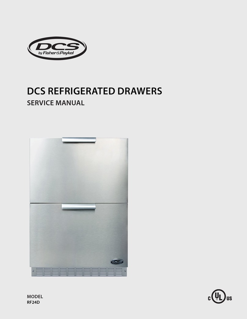
DCS ADR148 Installation guide

THE PROFESSIONAL ACCESS DRAWERS
Use and Care and Installation Guide
MODELS:
ADR148 ADR130
ADR136 ADR124


1
Thank you for selecting these DCS by Fisher & Paykel Professional Access Drawers. Because of this product’s unique features
we have developed this Installation Guide. It contains valuable information on how to properly install and maintain your
new Professional Access Drawers for years of safe and enjoyable use.
To help serve you better, please fill out and submit your Product Registration by visiting our website at www.dcsappliances.
com and selecting “Customer Care”on the home page and then select “Product Registration”. In addition, keep this guide
handy, as it will help answer questions that may arise as you use your new Access Drawers.
For your convenience, product questions can be answered by a DCS by Fisher & Paykel Customer Care Representative at
1-888-936-7872, or email: customer.care@fisherpaykel.com.
NOTE: Inspect the product to verify that there is no shipping damage. If any damage is detected, call the shipper and initiate
a damage claim. DCS by Fisher & Paykel is not responsible for shipping damage.
DO NOT discard any packing material (box, pallet, straps) until the unit has been inspected.
FOR YOUR SAFETY
Do not allow children or pets to play in or around the Access Drawers.1.
Clean the Access Drawers regularly using a mild dish washing liquid and water.2.
To maintain the exterior appearance, apply a stainless steel polish to the outside surfaces on a regular basis.3.
Sanitize the Access Drawers surfaces each season as necessary.4.
To prevent the formation of mold or mildew, do not store cloth napkins or tablecloths in the Access Drawers for long5.
periods.
Cooking utensils that are stored in the Access Drawers should be stored in6.
sealable plastic bags and/or washed each time before re-use.
To prevent personal injury or damage to the drawers, do not overload them.7.
The maximum rating per drawer is 75 pounds.
A MESSAgE TO OUR CUSTOMERS
WARNINg
Do Not store or use gasoline or other flammable vapors and liquids inside or in the vicinity of this or any other1. appliance.
An LP cylinder not connected for use shall not be stored inside or in the vicinity of this unit.2.
• Closing drawers may cause injury to
your hands or fingers.
• Always close or open drawers using
their handles.
• Be sure to keep hands away from
drawer edges when opening or
closing drawers.
WARNING
Note: Please write the model, code, and serial numbers on this page for reference (located on the sticker on the rear brace in
the tank side - see Fig. 04).
Model number Code Serial number
2
TAblE OF CONTENTS
SAFETY PRACTICES AND PRECAUTIONS
Begin by insuring proper installation and servicing.1.
Follow the installation instructions in this manual.2.
To extend the service life of your product, be sure to follow the use and care guidelines in this manual.3.
WARNINg:
Do not store items of interest to children above or on the inside of any appliance. Children could be seriously
injured if they should climb onto or into the appliance to reach these items.
PlEASE RETAIN ThIS MANUAl FOR FUTURE REFERENCE
SAFETY PRACTICES & PRECAUTIONS 2
MODEL IDENTIFICATION & DIMENSIONS 3
SHIPPING INSPECTION 3
CABINET PREPARATION 4
INSTALLATION
Make Cutout and Installing Support Structure 5
Removing Drawers 6
Slide in Access Drawers and Mount to Support Structure 6
Re-installing Drawers 7-8
CARE & MAINTENANCE 9
SERVICE 10
WARRANTY 1112

3
MODEl IDENTIFICATION & DIMENSIONS
ShIPPINg INSPECTION
Fig. 1
Inspect the Access Drawers to verify that there is no1.
shipping damage.
If any damage is detected, call the shipper and2.
initiate a damage claim. DCS by Fisher & Paykel is not
responsible for shipping damage.
NOTE: Do not discard any packing material (box, pallet,
straps) until the unit has been inspected.
Operate the drawers to be sure they glide smoothly.■
Examine the drawer fronts to be sure there are no dents or■
scratches or discoloring.
Fig. 1a
Fig. 2
ADR148
ADR136
ADR130 ADR124
DIMENSIONS
Model DW H F
ADR148 231/2” 48” 217/8” 2”
ADR136 231/2” 36” 217/8” 2”
ADR130 231/2” 30” 217/8” 2”
ADR124 231/2” 24” 217/8” 2”
F
W
H
D

4
CAbINET PREPARATION
Cabinet face should be clean and flat.■
All angles must be at 90■ºand plumb.
Support structure must be resistant to moisture damage.■
All gas lines and plumbing must be done before installing access drawers.■
Do not use any harsh products (acid, solvent, sealers) around this unit.■
Any cabinet and/or ground preparations must be completed prior to installation.■

5
INSTAllATION
MAkE CUTOUT AND INSTAll SUPPORT STRUCTURE
Make a cut-out in your cabinet or island with the following dimensions (Fig. 3):1.
Place 2 X 4s to provide support for the Access Drawers structure in the locations indicated in the figure below (Fig. 4).2.
Board lengths are provided in the table below (Fig. 5).3.
When installing your support boards, be4.
sure they are level.
Ensure that the bottom of the center
5.
divider rests on top of the support
boards as shown (Fig. 4).
Fig. 5
Fig. 4
island cutout
1/2" Bottom of center divider to
C
B
A
A
B
ED
Sticker location of
Model, Serial, Code Number
*
CUTOUT DIMENSIONS
Model A
0,+1/8” B
0,+1/8” C D
ADR148 46” 20” 1.0”min. 1.0”min.
ADR136 34” 20” 1.0”min. 1.0”min.
ADR130 28” 20” 1.0”min. 1.0”min.
ADR124 22” 20” 1.0”min. 1.0”min.
NOTE: Each corner of the cutout should be 90º for the Access Drawers to fit properly.
SUPPORT BOARD DIMENSIONS
Model A B C D E
48” 2 X 20” 11/2”* 31/2” min. 14 12
36” 20” 11/2”* 31/2” min. 14
30” 2 X 20” 11/2”* 31/2” min. 14 12
24” 20” 11/2”* 31/2” min. 14
To ensure proper drawer operation, be sure
your support boards are flat & level.
*Dependent on application. Top of 2x4’s
must be 1/2” above the bottom edge of
the cutout.
Fig. 6
For proper
support & drawer
operation, insure
that support
boards are level
front to back &
side to side.
Support Board (typical) Support Boards
(typical)
FRONT VIEW TYPICAL END VIEW TYPICAL
Fig. 3
A
90º
B
Vent*
Vent*
Vent*
C
D
* Island installation to use minimum of 3 vents
providing 10 sq. in. per vent (typical).

6
INSTAllATION
Fig. 7
REMOvINg DRAWERS
Once the unit has been inspected, remove the drawers by pulling them out until their slider latch is visible. Carefully push the1.
latch down on the left side while pulling up on the right side and pull the drawers completely out of the frame (Fig. 7).
To prevent damage to surfaces, place the drawers on a stable surface on a protective towel or table cloth.2.
TO REMOVE THE ADR124 DRAWER, pull the drawer out and lift the end by the handle to disengage the rollers (Fig. 8).
SlIDE IN FRAME AND MOUNT TO SUPPORT STRUCTURE
With the help of an assistant, lift the unit and slide it into the cabinet cutout. Adjust for level and fit.1.
Locate mounting holes on the frame (Fig. 9 and views). Secure the unit using screws suited for the type of cabinet material.2.
NOTE: Depending on the wall thickness and location of mounting holes, an additional board may be required to properly
receive the screws.
Fig. 9
Slider latch
11-3/4"
4-1/8"
1-3/8"
(Ø1/4" )
Anchor hole
15/16"
Fig. 8
LIFT

7
INSTAllATION
Fig. 10
Fig. 11
Fig. 12
D r a we r Ca v i t y
Glide
RE-INSTAllINg DRAWERS
Re-install the drawers by extending their guides as shown in Fig. 10.1.
While holding the drawer parallel to the cabinet, carefully align & engage the ends of the glides.2.
Slide the drawer in about an inch so that the glides are supporting the back of the drawer (Fig. 11).
While holding the drawer up by the handle, pull the glides from the drawer cavity out over the3.
drawer glide until they click (Fig. 12).
As you push the drawers in, you will encounter moderate resistance. Continue to push the drawer all the way in to complete4.
the engagement process. The drawer will now glide smoothly in & out with light effort (Fig. 13).
Fig. 13
Slider latch
Drawer Glide properly
Engaged.

8
INSTAllATION
Fig. 14
Tank Receptacle
Fig. 15
Drain drawer
Rack & Rack Cover
Your LP tank will be installed in the recess provided in the bottom of the right compartment (Fig. 14).5.
When connecting the LP tank to your grill be certain that all connections are tight. Once gas connections are made, test for6.
gas leaks.
On models so equipped, install the two (2) racks provided into the opening by sliding them onto the rollers on the sidewalls7.
of the center cavity (Fig. 15).

The Access Drawers are made from corrosion-resistant and non-magnetic stainless steel. All parts of the Access Drawers
can be cleaned with hot soapy water, rinsed, dried and buffed to a shine with a soft, heavy cloth. Always try this first, as it is
the mildest cleaning procedure. There are many different stainless steel cleaners available. Always use the mildest cleaning
procedure first, scrubbing in the direction of the grain to avoid marring the surface The cleaner will be more effective when
used in the direction of the grain (polish lines).
Some brands of cleaners of the same type are harsher than others, read their directions. A scent or a propellant can make1. a
difference in the product, read the ingredients. Try on a small area first.
To touch up noticeable scratches in the stainless steel, sand very lightly with wet 100 grit emery paper in the direction of the2.
grain.
Specks of grease can gather on the surfaces of the stainless steel and bake on to3.
the surface and give the appearance of rust. For removal use an abrasive pad
(Scotch Brite is good) in conjunction with a stainless steel cleaner. Always rub in
the direction of the grain.
Use only clean sponges, soft cloths, paper towels, plastic non-metal soap pads for4.
cleaning or scouring as recommended in this section. (Use only soap pads with
soap still in them. An empty pad can scratch.)
Be sure to rinse all parts thoroughly and to wipe dry to avoid water marks.5.
NOTE: Stainless steel tends to corrode in presence of chlorides and
sulfides especially in coastal areas. To ensure corrosion prevention, wash
all stainless steel surfaces every 3-4 weeks with fresh water and stainless
cleaner.
bRAND NAME ClEANERS
In this section on cleaning, the use of name brands is intended only to indicate a type of cleaner. This does not constitute
an endorsement. The omission of any name brand cleaner does not imply its adequacy or inadequacy. Many products are
regional in distribution and can be found in local markets and department stores.
MAINTENANCE
After cleaning, use a stainless steel polish, such as Stainless Steel Magic® applied to the drawer and handle surfaces.
To maintain the smooth operation of the drawers, spray the bearing areas with silicone spray lubricant annually (Fig. 16).
ACCESSORIES
Freezer Pack (optional, Kit #70696A)(Fig. 17)1.
Waste Basket Holder (optional, Kit #70906)(Fig. 18)2.
Bottom Cover (optional, Kit #70907)(Fig. 19)3.
9
CARE & MAINTENANCE
Fig. 16
Lubrication
points
(Use
silicone
spray
annually)
Fig. 17 - Freezer Pack (optional) Fig. 18 - Waste Basket Holder (optional) Fig. 19 - Bottom Cover
(optional)

10
SERvICE
For warranty service, please contact your local service provider or DCS Customer Care Representative at (888) 936-7872 or go
to our website at www.dcsappliances.com and choose “customer care” to find your nearest Authorized Service Center. Before
you call, please have the following information ready:
Model Number (located on the sticker on the rear brace in the tank side - see Fig. 04).
■
Serial Number (located on the sticker on the rear brace in the tank side - see Fig. 04).■
Code Number (located on the sticker on the rear brace in the tank side - see Fig. 04).■
Date of installation■
A brief description of the problem■
Your satisfaction is of the utmost importance to us. If a problem cannot be resolved to your satisfaction, please write or email
us at:
Write:
Fisher & Paykel Appliances, Inc.
Attention: DCS Customer Care
5900 Skylab Road
Huntington Beach, CA 92647
email: customer.care@fisherpaykel.com

11
WARRANTY
lIMITED WARRANTY
When you purchase a new DCS by Fisher & Paykel Professional Access Drawers, you automatically receive a One Year Limited
Warranty covering parts and labor for the entire product, and a Five Year Limited Warranty on all stainless steel assemblies
(parts only) for servicing within the 48 mainland United States, Hawaii, Washington D.C. and Canada. In Alaska, the Limited
Warranty is the same except that you must pay to ship the Product to the service shop or for the service technician’s travel to
your home. Products for use in Canada must be purchased through the Canadian distribution channel to ensure regulatory
compliance. Surface corrosion and discoloration is not covered under warranty.
FIShER & PAYkEl UNDERTAkES TO:
Repair without cost to the owner either for material or labor any part of the Product, the serial number of which appears on
the Product, which is found to be defective. In Alaska, you must pay to ship the Product to the service shop or for the service
technician’s travel to your home.
If we are unable to repair a defective part of the Product after a reasonable number of attempts, at our option we may
replace the part or the Product, or we may provide you a full refund of the purchase price of the Product (not including
installation or other charges).
This warranty extends to the original purchaser and any succeeding owner of the Product for products purchased for
ordinary single-family home use. All service under this Limited Warranty shall be provided by Fisher & Paykel Appliances Inc.
or its Authorized Service Agent during normal business hours.
hOW lONg DOES ThIS lIMITED WARRANTY lAST?
Our liability under this Limited Warranty for the entire product expires One Year from the date of purchase of the Product by
the first consumer.
Our liability under any implied warranties, including the implied warranty of merchantability (an unwritten warranty that the
Product is fit for ordinary use) also expires One Year (or such longer period as required by applicable law) from the date of
purchase of the Product by the first consumer. Some states do not allow limitations on how long an implied warranty lasts,
so this limit on implied warranties may not apply to you.
ThIS WARRANTY DOES NOT COvER:
Service calls that are not related to any defect in the Product. The cost of a service call will be charged if the problem is notA.
found to be a defect of the Product. For example:
Correct faulty installation of the Product.1.
Instruct you how to use the Product.2.
Correct fault(s) caused by the user.3.
Change the set-up of the Product.4.
Unauthorized modifications of the Product.5.
Correcting damage caused by pests, for example, rats, cockroaches etc.6.
Discoloration or rust stains.7.
B. Defects caused by factors other than:
Normal domestic use or1.
Use in accordance with the Product’s User Guide.2.
The cost of repairs carried out by non-authorized repairers or the cost of correcting such unauthorized repairs.C.
Travel Fees and associated charges incurred when the product is installed in a location with limited or restricted access (i.e.D.
airplane flights, ferry charges, isolated geographic areas).
Normal recommended maintenance as set forth in the Product’s Care & User Guide.E.
Defects to the Product caused by accident, neglect, misuse, fire, flood or Act of God.F.

12
WARRANTY (continued)
If you have an installation problem contact your dealer or installer. You are responsible for providing adequate electrical,
exhausting and other connection facilities. We are not responsible for consequential or incidental damages (the cost of
repairing or replacing other property damaged if the Product is defective or any of your expenses caused if the Product is
defective). Some states do not allow the exclusion or limitation of incidental or consequential damages, so the above limita-
tion or exclusion may not apply to you.
hOW TO gET SERvICE
Please read your Care & User Guide. If you then have any questions about operating the Product, need the name of your
local DCS Authorized Service Agent, or believe the Product is defective and wish service under this Limited Warranty, please
contact your dealer or call us at:
TOLL FREE 1-888-936-7872 or contact us through our web site: www.dcsappliances.com.
You may be required to provide reasonable proof of the date of purchase of the Product before the Product will be serviced
under this Limited Warranty.
COMMERCIAl USE
This warranty applies to appliances used in residential applications; it does not cover their use in commercial situations.
NO OThER WARRANTIES
This Limited Warranty is the complete and exclusive agreement between you and Fisher & Paykel Appliances Inc. regarding
any defect in the Product. None of our employees (or our Authorized Service Agents) are authorized to make any addition or
modification to this Limited Warranty.
Warrantor: Fisher & Paykel Appliances, Inc.
If you need further help concerning this Limited Warranty, please call us at the above number, or write to:
Fisher & Paykel Appliances, Inc.
Attention: DCS Customer Care
5900 Skylab Road, Huntington Beach, CA 92647
This Limited Warranty gives you specific legal rights, and you may also have other rights which vary from state to state.
Fisher & Paykel Appliances Inc. is a leading manufacturer of premium quality cooking and specialty appliances under the
Fisher & Paykel and DCS by Fisher & Paykel brands.

LES TIROIRS PROFESSIONNELS
Manuel d’utilisation, d’entretien et d’installation
MODÈLES :
ADR148 ADR130
ADR136 ADR124

1
Nous vous remercions d’avoir choisi ces tiroirs professionnels DCS by Fisher & Paykel. Nous avons conçu ce Manuel
d’utilisation et d’entretien pour expliquer les fonctions uniques de ces appareils. Ce manuel contient des informations
extrêmement utiles sur la façon correcte de les installer, les faire fonctionner et en faire l’entretien. Vous pourrez ainsi en
profiter pendant des années en toute sécurité.
Aidez-nous à mieux vous servir en remplissant l’enregistrement de produit et en nous le soumettant depuis notre site Web à
www.dcsappliances.com. Sélectionnez « Customer Care » sur la page d’accueil puis « Product Registration ». De plus, gardez
ce manuel à portée de main afin de rapidement trouver réponse à vos questions durant l’utilisation de votre nouvel appareil.
Si vous avez des questions au sujet de notre produit, communiquez avec un représentant du centre de service à la clientèle
REMARQUE : Veuillez noter les numéros de modèle, code, et de série sur cette page pour information (situé sur l’autocollant
sur la contrefiche arrière du côté réservoir - voir Fig. 04)
NUMÉRO DE MODÈLE CODE NUMÉRO DE SÉRIE
REMARQUE : Inspecter le produit pour vérifier qu’il n’a pas été endommagé pendant l’expédition. En cas de dommages,
contacter le transporteur et entamer une déclaration pour dommage. DCS by Fisher & Paykel n’est en aucun cas responsable
des dommages pendant l’expédition.
Ne pas jeter le matériau d’emballage (boîte, palette, sangles) avant d’avoir inspecté l’unité.
POUR vOTRE SÉCURITÉ
1. Ne laissez pas des enfants ou des animaux de compagnie jouer à l’intérieur ou autour des tiroirs.
2. Nettoyez les tiroirs périodiquement avec un détergent liquide pour
vaisselle doux et de l’eau.
3. Pour préserver l’aspect extérieur, appliquez un produit à polir pour acier
inoxydable sur les surfaces extérieures sur une base régulière.
4. Désinfectez les surfaces des tiroirs à chaque saison au besoin.
5. Pour éviter la formation de moisissure, évitez de ranger des serviettes
de table en tissu ou des nappes dans les tiroirs pendant des périodes
prolongées.
6. Les ustensiles de cuisson rangés dans les tiroirs doivent être placés dans
des sacs en plastique scellables ou lavés chaque fois avant d’être réutilisés.
7. Pour éviter des blessures corporelles ou ne pas endommager les tiroirs,
évitez de les surcharger. Le poids maximum par tiroir est de 34 kg (75 lb).
A l’INTENTION DE NOS ClIENTS
AvERTISSEMENT
1. Évitez de stocker ou d’utiliser de l’essence ou tout autre liquide et vapeur inflammable à l’intérieur ou à proximité de
cet appareil ou de tout autre.
2. Évitez de ranger une bouteille de gaz propane (qui n’est pas connectée car non utilisée) à l’intérieur ou à proximité
de cet appareil ou de tout autre.
• Closing drawers may cause injury to
your hands or fingers.
• Always close or open drawers using
their handles.
• Be sure to keep hands away from
drawer edges when opening or
closing drawers.
WARNING

2
TAblE DES MATIERES
MESURES DE SECURITE ET DE PRECAUTION
Commencez par vous assurer que l’installation et l’entretien sont effectués correctement.1.
Suivez les instructions d’installation du manuel.2.
Pour prolonger la durée de vie utile du produit, suivez les consignes d’utilisation et d’entretien de ce manuel.3.
AvERTISSEMENT :
Évitez de ranger au-dessus ou à l’intérieur d’un quelconque appareil des articles pouvant attirer les enfants.
Ceux-ci peuvent se blesser sérieusement s’ils grimpent sur ou à l’intérieur de l’appareil pour atteindre l’objet en
question.
MESURES DE SECURITE ET DE PRECAUTION 2
IDENTIFICATION DU MODELE ET DIMENSIONS 3
INSPECTION APRES LIVRAISON 3
PRÉPARATION DE L’ÉLÉMENT 4
INSTALLATION
Effectuer la découpe et installer la structure de support 5
Retrait des tiroirs 6
Enfoncer les tiroirs et les monter sur la structure de support 6
Réinstallation des tiroirs 7-8
ENTRETIEN ET MAINTENANCE 9
ACCESSOIRES 10
SERVICE 11
GARANTIE 1213

D
3
IDENTIFICATION DU MODElE ET DIMENSIONS
INSPECTION APRES lIvRAISON
Fig. 1
Inspectez les tiroirs pour vous assurer qu’ils n’ont subi aucun1.
dommage durant le transport.
Le cas échéant, appelez le transporteur et soumettez une2.
réclamation pour dommages. DCS by Fisher & Paykel n’est
pas responsable des dommages subis durant le transport.
REMARQUE : Ne jetez aucun matériel d’emballage (boîte,
palette, sangles) avant d’avoir inspecté l’appareil.
Faites fonctionner les tiroirs pour vous assurer qu’ils glissent■
correctement.
Examinez le devant des tiroirs pour vous assurer qu’il n’y a■
aucune bosse ou égratignure.
Fig. 1a
Fig. 2
DIMENSIONS/COTES
MODELE D W H F
ADR148 59,7 cm 121,9cm 55,6 cm 5,1 cm
ADR136 59,7 cm 91,4 cm 55,6 cm 5,1 cm
ADR130 59,7 cm 76,2 cm 55,6 cm 5,1 cm
ADR124 59,7 cm 61 cm 55,6 cm 5,1 cm
W
H
F
ADR130 ADR124
ADR136
ADR148

4
PRÉPARATION DE l’ÉlÉMENT
La face de l’élément doit être propre et plate.■
Tous les angles doivent être de 90º et d’équerre.■
La structure de support doit être résistante aux dommages de l’humidité.■
Toutes les conduites de gaz et tuyauteries doivent être effectuées avant d’installer les tiroirs d’accès.■
Ne pas utiliser de produits abrasifs (acide, solvant, produit d’étanchéité) autour de cette unité.■
Toutes les préparations d’élément et/ou de sol doivent être terminées avant l’installation.■

5
INSTAllATION
EFFECTUER lA DECOUPE ET INSTAllER lA STRUCTURE DE SUPPORT
Effectuez une découpe dans votre armoire ou îlot avec les dimensions suivantes (Fig. 3) :1.
REMARQUE : Chaque coin de découpe doit être de 90º pour que les tiroirs d’accès entrent correctement.
Placez des pièces 2 x 4 pour fournir un support à la structure des tiroirs aux emplacement indiqués sur la figure ci-dessous2.
(Fig. 4).
La longueur des planches est indiquée dans le tableau ci-dessous (Fig. 5).3.
Fig. 5
A
90º
B
Vent*
Vent*
Vent*
C
D
Fig. 4
Le fond du séparateur central à la
découpe de l'îlot est de 1/2 po
C
B
A
A
B
ED
Emplacement de
l'autocollant des
numéros de modèle,
code et série.
*
DIMENSIONS DES DECOUPES
MODELE A
0,+0,3cm B
0,+0,3cm C D
ADR148 116,8 cm 50,8 cm 2,54 cm min. 2,54 cm min.
ADR136 86,4 cm 50,8 cm 2,54 cm min. 2,54 cm min.
ADR130 71,2 cm 50,8 cm 2,54 cm min. 2,54 cm min.
ADR124 56 cm 50,8 cm 2,54 cm min. 2,54 cm min.
DIMENSIONS DES PLANCHES DE SUPPORT
A B C D E
48 po 2 X 5,1
cm 3,8 cm* 8,9 cm min. 35,6 cm 30,5 cm
36 po 5,1 cm 3,8 cm* 8,9 cm min. 35,6 cm
30 po 5,1 cm 3,8 cm* 8,9 cm min. 35,6 cm 30,5 cm
24 po 5,1 cm 3,8 cm* 8,9 cm min. 35,6 cm
Afin d’assurer le bon fonctionnement des tiroirs, assurez-vous que les
planches de support sont plates et de niveau.
* Prévoir pour l’installation en îlot 3
évents minimum à raison de 64 cm2 (10
po2) par évent (installation typique).
Fig. 6
Pour permettre
un support et un
fonctionnement
adéquat des tiroirs,
assurez-vous que
les planches de
support sont de
niveau de l’avant
à l’arrière et d’un
côté à l’autre.
Planche de support
(typique) Planches de
support (typique)
Vue de face (typique) Vue de l’extrémité (typique)
Fig. 3
Lors de l’installation des planches de4.
support, assurez-vous qu’elles sont de
niveau.
S’assurer que le fond du séparateur5.
central repose sur les planches de
support comme il l’est illustré (Fig. 4).
*En fonction de l’application. Dessus des 2 x 4
doit être à 1/2” au-dessus du chant inférieur
de la découpe.
This manual suits for next models
3
Table of contents
Languages:
Other DCS LCD Drawer manuals